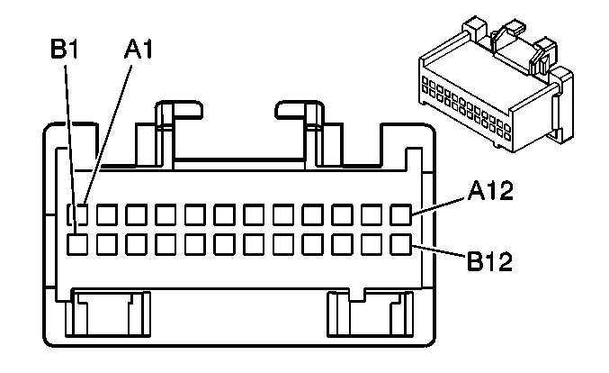
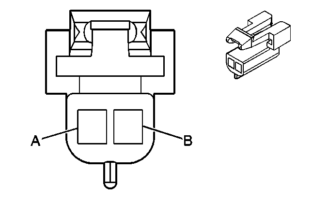
| Table 1: | Radio |
| Table 2: | Speaker - LF |
| Table 3: | Speaker - LR |
| Table 4: | Speaker - RF |
| Table 5: | Speaker - RR |

| |||||||
|---|---|---|---|---|---|---|---|
Connector Part Information |
| ||||||
Pin | Wire Color | Circuit No. | Function | ||||
A1 | PPL | 1807 | Class 2 Serial Data | ||||
A2-A7 | -- | -- | Not Used | ||||
A8 | TAN | 201 | Left Front Speaker Output (+) | ||||
A9 | GRY | 118 | Left Front Speaker Output (-) | ||||
A10 | LT BLU | 115 | Right Rear Speaker Output (-) | ||||
A11 | DK BLU | 46 | Right Rear Speaker Output (+) | ||||
A12 | BLK/WHT | 151 | Ground | ||||
B1 | ORN | 1740 | Battery Positive Voltage | ||||
B2-B3 | -- | -- | Not Used | ||||
B4 | GRY | 8 | Instrument Panel Lamps Dimmer Switch Signal | ||||
B5 | BLK | 250 | Ground | ||||
B6-B7 | -- | -- | Not Used | ||||
B8 | BRN | 199 | Left Rear Speaker Output (+) | ||||
B9 | YEL | 116 | Left Rear Speaker Output (-) | ||||
B10 | DK GRN | 117 | Right Front Speaker Output (-) | ||||
B11 | LT GRN | 200 | Right Front Speaker Output (+) | ||||
B12 | BRN | 9 | Park Lamp Supply Voltage | ||||

| |||||||
|---|---|---|---|---|---|---|---|
Connector Part Information |
| ||||||
Pin | Wire Color | Circuit No. | Function | ||||
A | GRY | 118 | Left Front Speaker Output (-) | ||||
B | TAN | 201 | Left Front Speaker Output (+) | ||||

| |||||||
|---|---|---|---|---|---|---|---|
Connector Part Information |
| ||||||
Pin | Wire Color | Circuit No. | Function | ||||
A | YEL | 116 | Left Rear Speaker Output (-) | ||||
B | BRN | 199 | Left Rear Speaker Output (+) | ||||

| |||||||
|---|---|---|---|---|---|---|---|
Connector Part Information |
| ||||||
Pin | Wire Color | Circuit No. | Function | ||||
A | DK GRN | 117 | Right Front Speaker Output (-) | ||||
B | LT GRN | 200 | Right Front Speaker Output (+) | ||||

| |||||||
|---|---|---|---|---|---|---|---|
Connector Part Information |
| ||||||
Pin | Wire Color | Circuit No. | Function | ||||
A | LT BLU | 115 | Right Rear Speaker Output (-) | ||||
B | DK BLU | 46 | Right Rear Speaker Output (+) | ||||
