Removal Procedure
Caution: Refer to Approved Equipment for Collision Repair Caution in the Preface section.
Caution: Sectioning should be performed only in the recommended areas. Failure to do so may compromise the structural integrity of the vehicle and cause personal injury if the vehicle is in a collision.
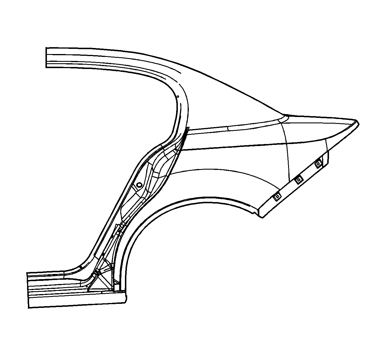
Important: The procedures for the coupe and the sedan are similar. However, the sedan has a rear latch striker reinforcement that is structurally bonded to the outer body side panel at the dog leg area of the quarter panel.
You can perform any one of these replacement procedures separately or in any combination, depending upon the extent of damage to the vehicle. Sectioning must take place in specified areas only. Stay away from the door and window opening radius areas. Section only in straight areas of the openings.
- Disable the SIR system. Refer to SIR Disabling and Enabling in SIR.
- Disconnect the negative battery cable. Refer to Battery Negative Cable Disconnection and Connection in Engine Electrical.
- Remove all related panels and components.
- Repair as much of the damaged area as possible. Refer to Dimensions - Body .
- Remove the sound deadeners as necessary. Note their location.
- Remove the sealers and anti-corrosion materials from the repair area, as necessary. Refer to Anti-Corrosion Treatment and Repair in Paint and Coatings.
- For the sedan, sectioning can be performed at any of the following locations:
- For the coupe:
- Within the recommended sectioning areas, mark the location of the sectioning cut lines on the vehicle.
- Locate and drill out all factory welds.
- Cut the panel according to the location chosen and laid out in the previous steps.
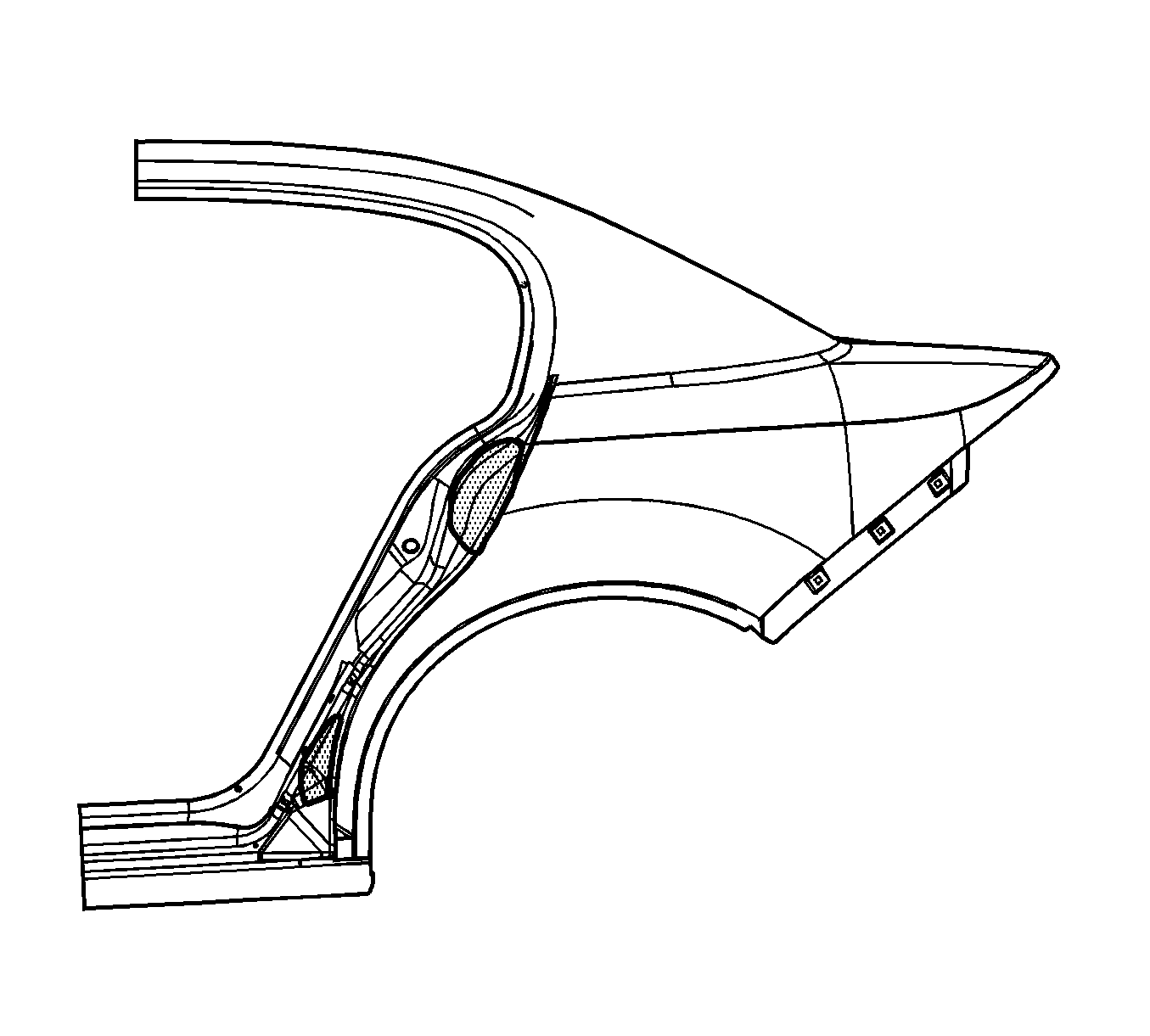
- On the sedan, structural adhesive is present in the dog leg area of the quarter panel. Heat the quarter panel at the locations shown with a small flame from an oxy-acetylene torch to release the bond to the quarter panel.
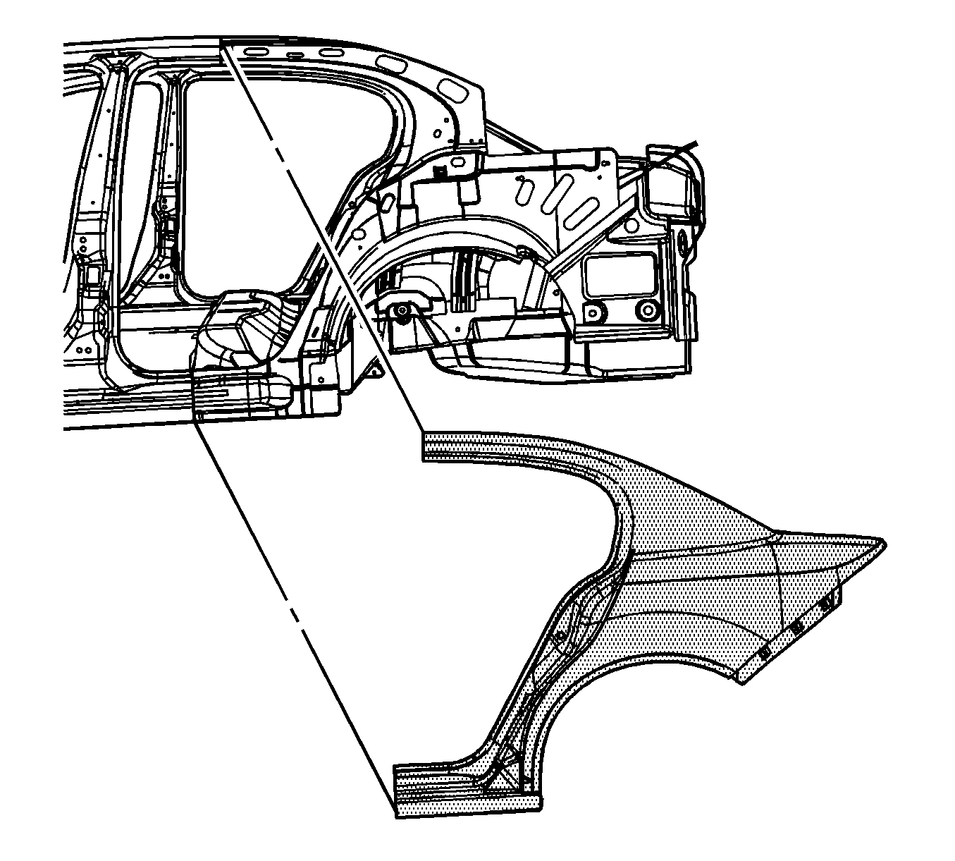
- Remove the damaged quarter panel.
Important: The wheel opening flange should bend upwards. Do not repair this normal condition. Take note of the shape of the flange for installation purposes. Do not flatten the flange.
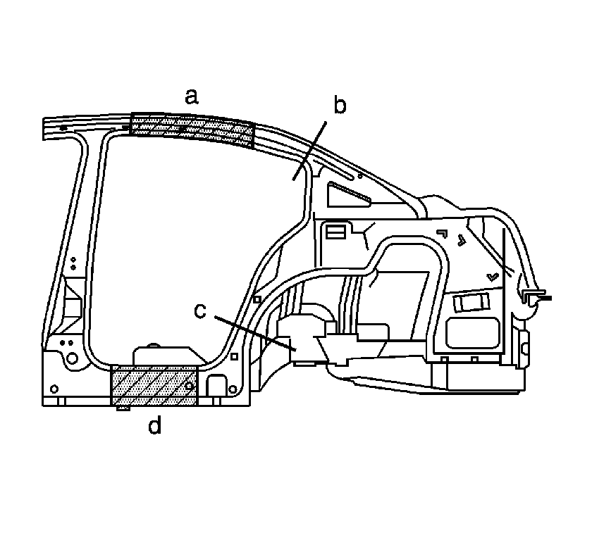
Important: Perform sectioning only in the recommended areas of the rocker panel, the sail panel, and the upper roof rail area of the body side panel as necessary.
| Important: Avoid areas in the radius corners for the rear header attachment locations. |
| • | (a) - The butt joint and the weld backer, located on any straight area along the top of the rear door opening forward of the header panel and rearward of the center pillar radius. Use a 100-mm (4-in) welding backer. |
| • | (b) - The overlap and the plug weld joint. This joint will be an overlap. Cut the service part no higher than the cut on the original panel by 50 mm (2 in). |
| • | (c) - The butt joint and the weld backer, located on any straight area along the bottom of the rear door opening and between the pillar lower radii. Use a 100-mm (4-in) weld backer. |
| Important: Avoid areas in the lower radius corners, at the bottom of the center pillar, and at the dog leg in the door opening. |
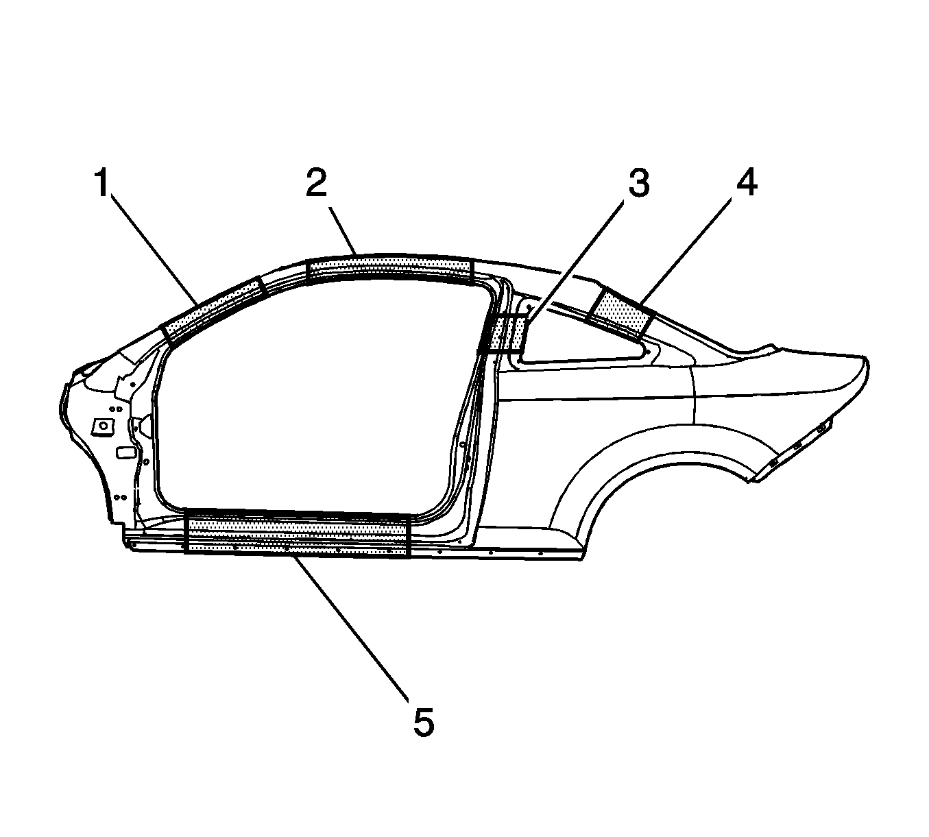
| • | 3 - Use a 50 mm (2 in) weld backer. |
| • | 4 - Use a 50 mm (2 in) weld backer. |
| • | 5 - Use a 100 mm (4 in) weld backer. |
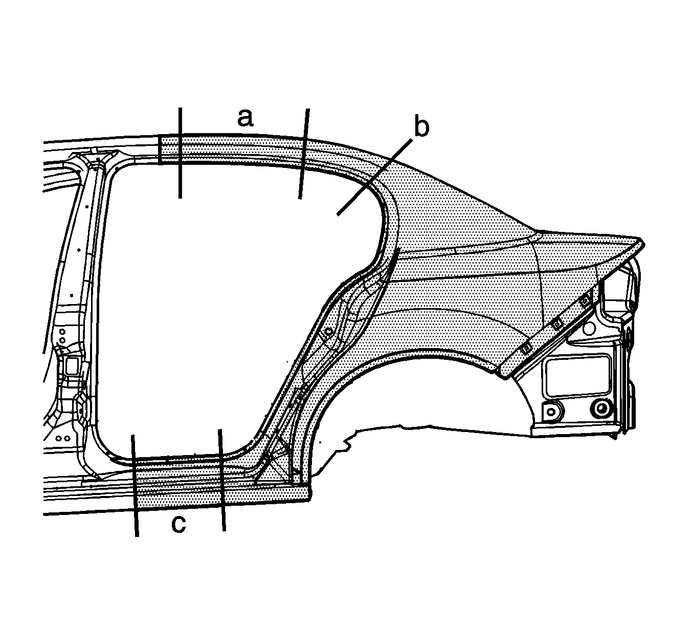
Important: Note the number and location of the factory welds for installation of the quarter panel.
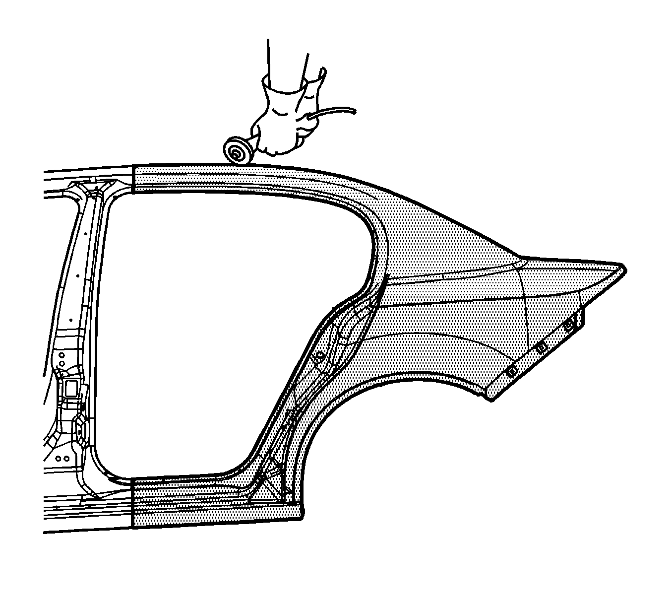
Important: Do NOT damage any other panels or reinforcements when cutting at the marked locations.
Installation Procedure
- Locate the area on the service panel where you will perform sectioning.
- Measure and mark the cut line location on the service part, according to the location chosen and laid out in the previous Removal Procedure.
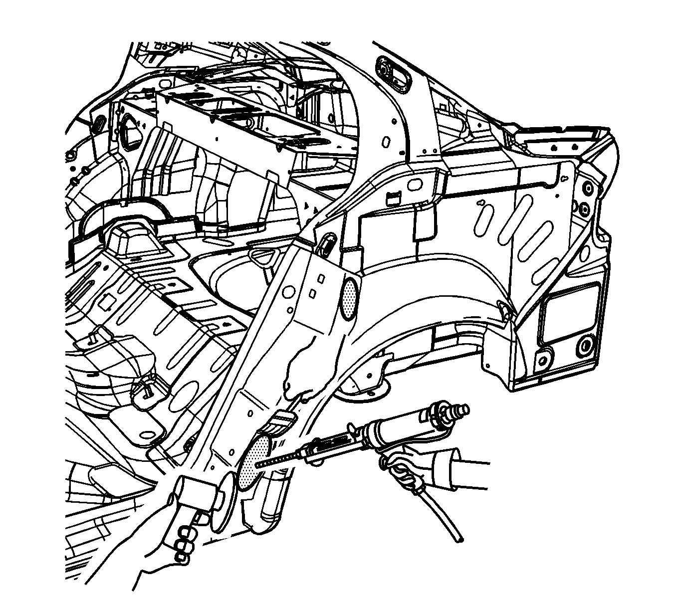
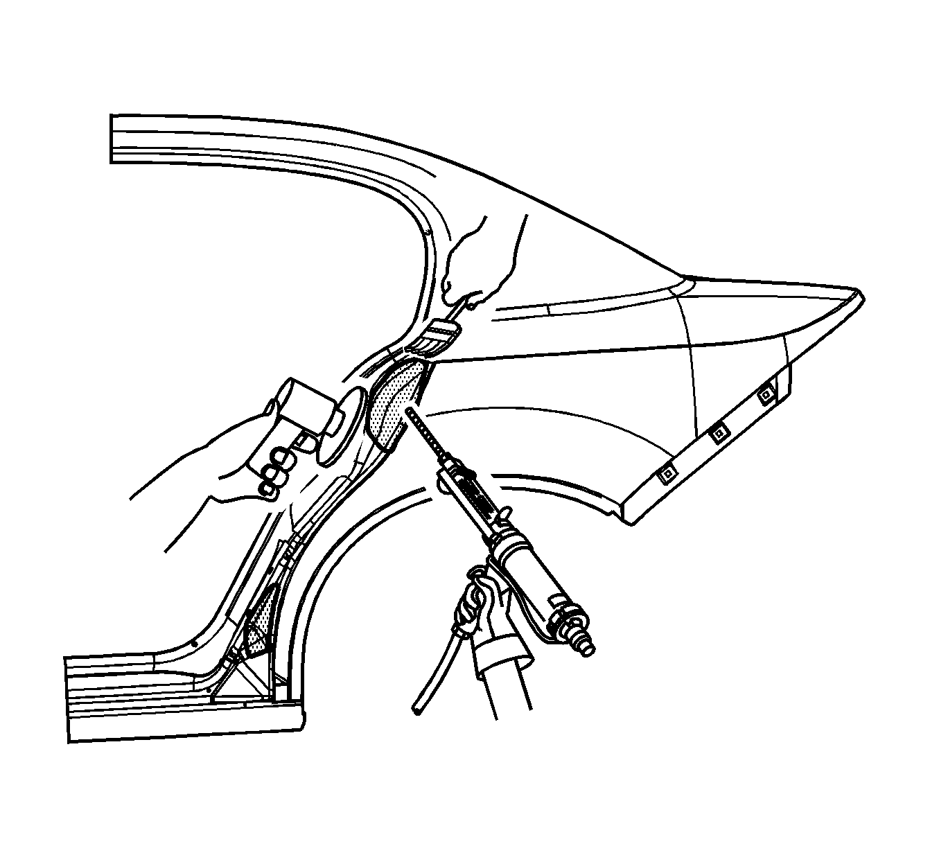
- Grind the surface of the dog leg inner reinforcement to bare steel at the structural adhesive locations.
- Grind the quarter panel mating area to the dog leg reinforcement to remove the E-coating.
- Clean the mating surfaces.
- Apply a bead of metal panel bonding adhesive GM P/N 12378566/7 (Canadian P/N 88901674/5) or equivalent to a thickness of 3-6 mm (1/8 to 1/4 in) to both of the mating surfaces.
- Using a small acid brush, spread a coat of adhesive to cover all of the bare metal surfaces to ensure corrosion protection.
- Install the quarter panel to the vehicle. Clamp the quarter panel into position as necessary.
- Cut the service panel in corresponding locations to fit the remaining original panel. Trim the sectioning butt joint to allow a gap of 1½ times the metal thickness at the sectioning joint.
- Create backing plates of the previously specified length from the unused portion of the service part.
- Trim the backing plates as necessary to fit behind the panel at the sectioning joints.
- Drill 8 mm (5/16 in) plug weld holes along the sectioning areas in the service part. Drill the plug weld holes 15 mm (5/8 in) from the edges.
- Drill 8 mm (5/16 in) plug weld holes at the locations noted from the original panel.
- Prepare all mating surfaces as necessary.
- Apply 3M Weld-Thru Coating P/N 05916 or equivalent to all mating surfaces.
- Fit the backing plates halfway into the sectioning joints on the vehicle. Clamp the plates in place, and plug weld to the section joint
- Weld the plug weld holes on the vehicle half of the backing plates.
- Position the quarter panel service part to the vehicle using 3-dimensional measuring equipment. Clamp the quarter panel in place.
- Plug weld accordingly.
- Bend the wheel opening weld flange upward as noted during the Removal Procedure.
- To create a solid weld with minimum heat distortion, make a 25 mm (1 in) stitch weld along the seam with gaps of 25 mm (1 in). Go back and complete the stitch weld.
- Clean and prepare all of the welded surfaces.
- Apply the sealers and anti-corrosion materials to the repair area, as necessary. Refer to Anti-Corrosion Treatment and Repair in Paint and Coatings.
- Paint the repaired area. Refer to Basecoat/Clearcoat Paint Systems in Paint and Coatings.
- Install all of the related panels and components.
- Connect the negative battery cable. Refer to Battery Negative Cable Disconnection and Connection in Engine Electrical.
- Enable the SIR system. Refer to SIR Disabling and Enabling in SIR.
Important: To allow proper layout and cutting of the service port, review the appropriate sectioning area information in the removal procedure.
Important: Do not damage the corners or thin the metal during the grinding process.
Important: The adhesive has a working time of 40-50 minutes. DO not allow the adhesive to totally cure off the vehicle, as the proper alignment of the panel to the body will be difficult.
Important: Spread the adhesive thick enough to ensure panel contact between the dog leg inner reinforcement and the quarter panel.
Important: Do not pull the panels apart after the panels have been joined together. Slide the panels against each other to align the panels.
Important: If the location of the original plug weld holes can not be determined, space the plug weld holes every 40 mm (1½ in) apart.
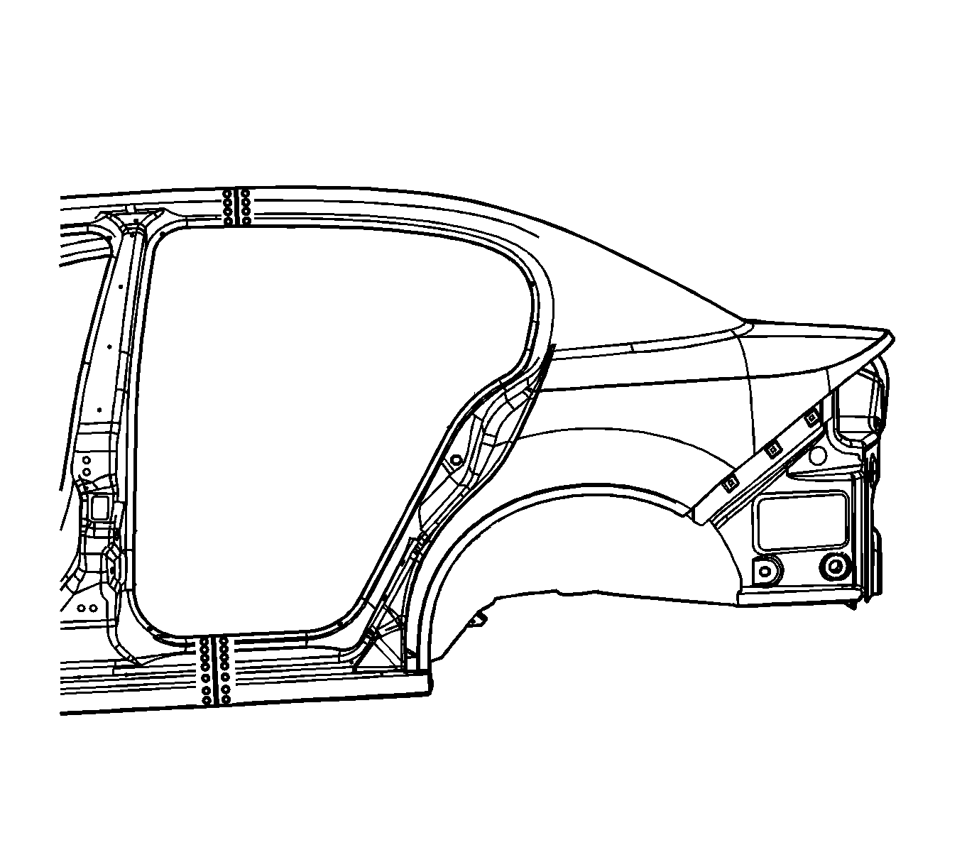
Important: Weld in areas other than the wheelhouse weld flange first. Do not weld the quarter panel wheel opening weld flange until the rest of the panel has been welded and the wheel opening weld flange lip has been bent upward. This bent flange ensures that the tire does not make contact with this flange.
Important: Use care when bending the flange to prevent damage to the visible surface of the service panel.
