Laminated Steels - General Information and Specific Repair Procedures for Hinge Pillar Body Replacement-Front Inner, Rail Replacement Front Compartment-Front and Wheelhouse Replacement-Front

| Subject: | Laminated Steels - General Information and Specific Repair Procedures for Hinge Pillar Body Replacement-Front Inner, Rail Replacement Front Compartment-Front and Wheelhouse Replacement-Front |
| Models: | 2005 Chevrolet Cobalt |
| 2005 Pontiac Pursuit (Canada Only) |
This bulletin is being revised to add a model. Please discard Corporate Bulletin Number 05-08-98-002 (Section 08 - Body and Accessories).
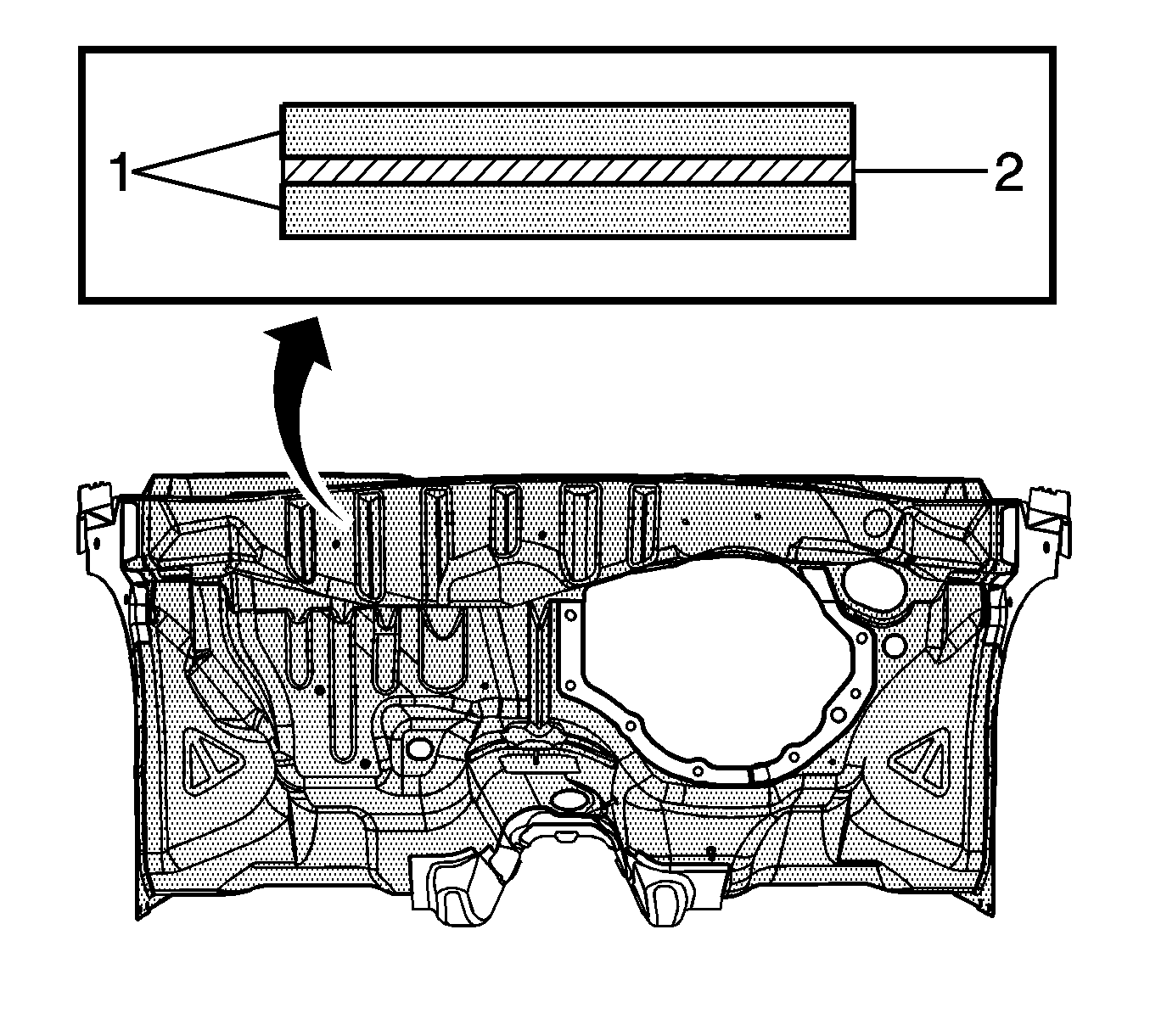
Laminated steel consists of three layers of material: two layers of mild steel with a layer of "visco-elastic" material between them. This "sandwich" of material layers provides better sound absorbing properties than regular, non-laminated materials.
Laminated steel is being used on the 2005 Chevrolet Cobalt/Pontiac Pursuit to enhance the acoustic performance. Currently, the front dash panel and the lower plenum panel are made from laminated steel.
This material is very different than standard steel applications. Because of these differences, it requires different repair procedures to be used when replacing components that attach directly to the laminated steel surfaces. Those components are typically structural rails, front wheelhouse/shock towers and front body hinge pillar inner panels. Depending on the design and build of the vehicle, though, some of the components may not attach directly to the laminated steel surface. Components that do not attach directly to the laminated steel surface may be attached in the normal manner.
General Repairability Guidelines
| • | MIG welding of this material is not recommended due to contamination of the weld from the "visco-elastic" layer. |
| • | Rivet/bonding of components that attach to laminated steel surfaces is recommended. This process uses a structural rivet combined with metal panel bonding adhesives currently recommended by GM that meet the performance requirements of GM 6449G (guidelines for adhesive manufacturers to develop metal panel bonding adhesives). |
| • | Resistance spot welding is recommended where the plier or jaw openings and reach of the tool will allow. Refer to the GM Dealer Equipment Catalog for current recommendations of resistance spot welding equipment or call 1-800-GMTOOLS. |
| • | Laminated steel can be straightened cold or with heat. If heat is required, temperatures should be controlled to less than 649°C (1,200°F) and the duration of the heat should be kept to less than 3 minutes overall (it is preferable that this be done in multiple steps). Heating this material following these guidelines will not effect the acoustical performance of this material. |
Refer to GM Service Information for the 2005 Chevrolet Cobalt/Pontiac Pursuit for specific procedures related to the components that attach to laminated steels. The procedures below have recently been added to SI. Additional procedures are currently being developed and Service Manual Update bulletins will be published to inform dealers of this new information.
Hinge Pillar Body Replacement - Front Inner
Important: Failure to follow this procedure will compromise the structural integrity of the vehicle.
The front of the dash panel and plenum lower are formed from laminated steel. This steel is constructed by bonding 2 pieces of cold rolled steel with a viscosities layer of adhesive. MIG welding laminated steel does not meet GM Corporate standards for structural integrity. As an alternative, all factory welds may be replaced by using the rivet and adhesive bond method described in the installation portion of this procedure. The rivet and adhesive bond method must only be used in the areas described in this procedure.
Removal Procedure
- Disable the SIR system. Refer to SIR Disabling and Enabling Zones in SIR.
- Disconnect the negative battery cable. Refer to Battery Negative Cable Disconnect/Connect Procedure in Engine Electrical.
- Remove the sealers and anti-corrosion materials from the repair area, as necessary. Refer to Anti--Corrosion Treatment and Repair in Paint/Coatings.
- Visually inspect the damaged area. Repair as much of the damage as possible. Refer to Dimensions--Body .
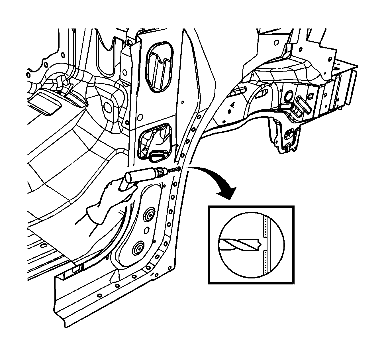
- Using an 8 mm (5/16 in) spot weld remover, locate and drill out the factory welds on the weld flange connecting the front inner hinge pillar to the dash panel.
- Locate and drill out all remaining factory welds.
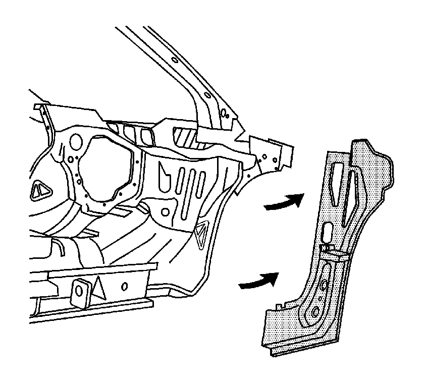
- Remove the front inner hinge pillar from the vehicle.
Caution: Refer to Approved Equipment for Collision Repair Caution in Cautions and Notices.
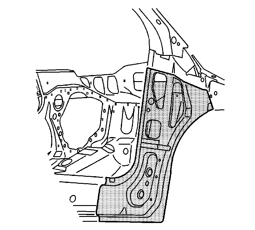
Important: Drill through the front inner hinge pillar flange only. Do not drill into the dash panel.

Important: Note the number and location of welds for installation of the front inner hinge pillar.
Installation Procedure
- Position the service front inner hinge pillar in the vehicle using 3-dimensional measuring equipment. Clamp the front inner hinge pillar in place.
- Using a 7 mm (17/64 in) bit, drill the rivet attachment holes through the dash and the lower rail extension in the locations as noted from the factory front inner hinge pillar.
- Remove the service front inner hinge pillar.
- Drill 8 mm (5/16 in) plug weld holes as necessary in the locations noted from the original assembly.
- Prepare the MIG weld mating surfaces as necessary.
- Apply 3M® Weld-Thru Coating, P/N 05916, or equivalent, to all MIG weld mating surfaces.
- Prepare the bonding mating areas by grinding to bare steel the surface of the dash panel and rail extension to the service front inner hinge pillar flanges.
- Apply a 3-6 mm (1/8-1/4 in) bead of metal panel bonding adhesive, P/N 12378567 (Canadian P/N 88901675), or equivalent, to the mating surfaces of the dash panel and the rail extension, and the front inner hinge pillar service panel.
- Using a small acid brush, spread a coating of adhesive on the mating surfaces. Cover all of the bare metal to ensure corrosion protection.
- Position the service front inner hinge pillar to the vehicle using 3-dimensional measuring equipment. Clamp the front inner hinge pillar in place.
- Install the 14 mm (17/32 in) long rivets so that the rivet head contacts the rail extension.
- Install the 9 mm (11/32 in) long rivets so that the rivet head contacts the dash panel.
- Remove the excess adhesive from the front inner hinge pillar bond rivet area.
- Plug weld accordingly.
- Clean and prepare all of the welded surfaces.
- Apply the sealers and anti-corrosion materials to the repair area, as necessary. Refer to Anti--Corrosion Treatment and Repair in Paint/Coatings.
- Paint the repaired area. Refer to Basecoat/Clearcoat Paint Systems in Paint/Coatings.
- Install all related panels and components.
- Connect the negative battery cable. Refer to Battery Negative Cable Disconnect/Connect Procedure in Engine Electrical.
- Enable the SIR system. Refer to SIR Disabling and Enabling Zones in SIR.
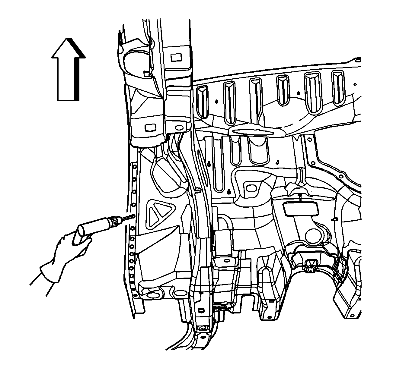

Important: If the location of the original plug weld holes can not be determined, space the plug weld holes every 40 mm (1 1/2 in) apart.
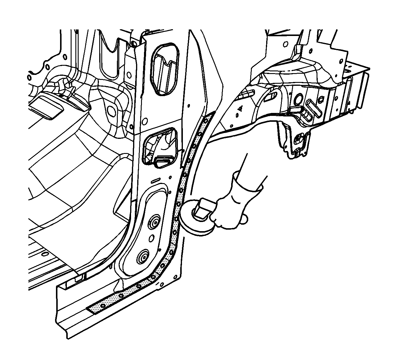
Important: Do not damage the corners or thin the metal during the grinding process.
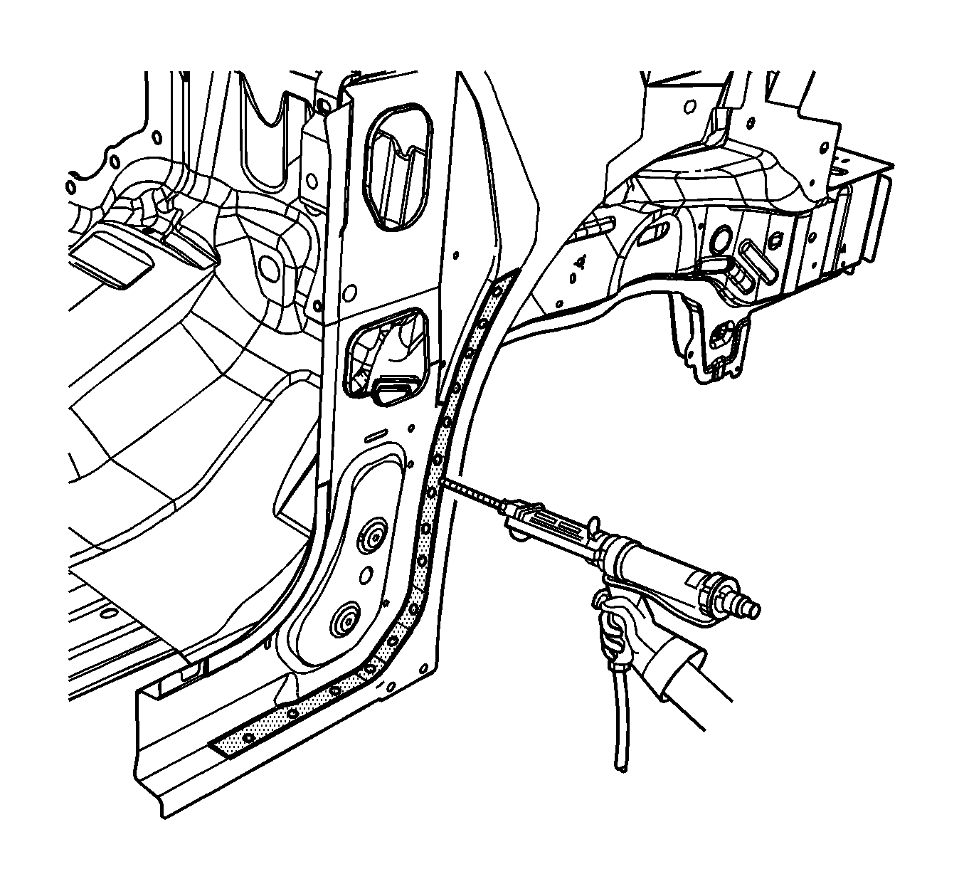
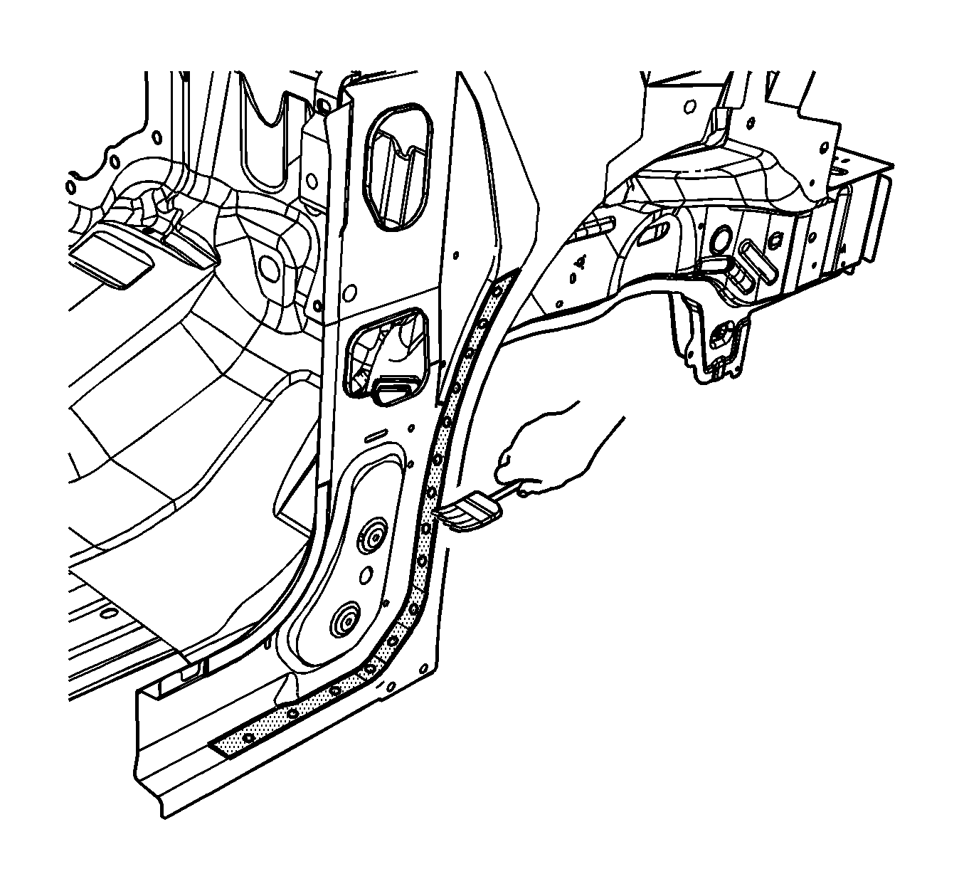
Important: Do not pull the front inner hinge pillar off of the dash after adhesion. To align the parts, slide the front inner hinge pillar against the dash panel.
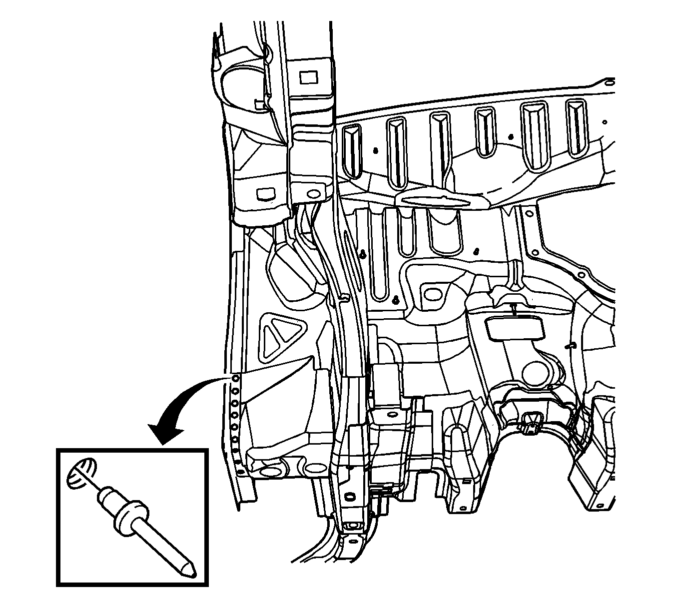
Important: Verify the proper positioning of the service front inner hinge pillar prior to riveting and welding.

Rail Replacement Front Compartment - Front
Important: Failure to follow this procedure will compromise the structural integrity of the vehicle.
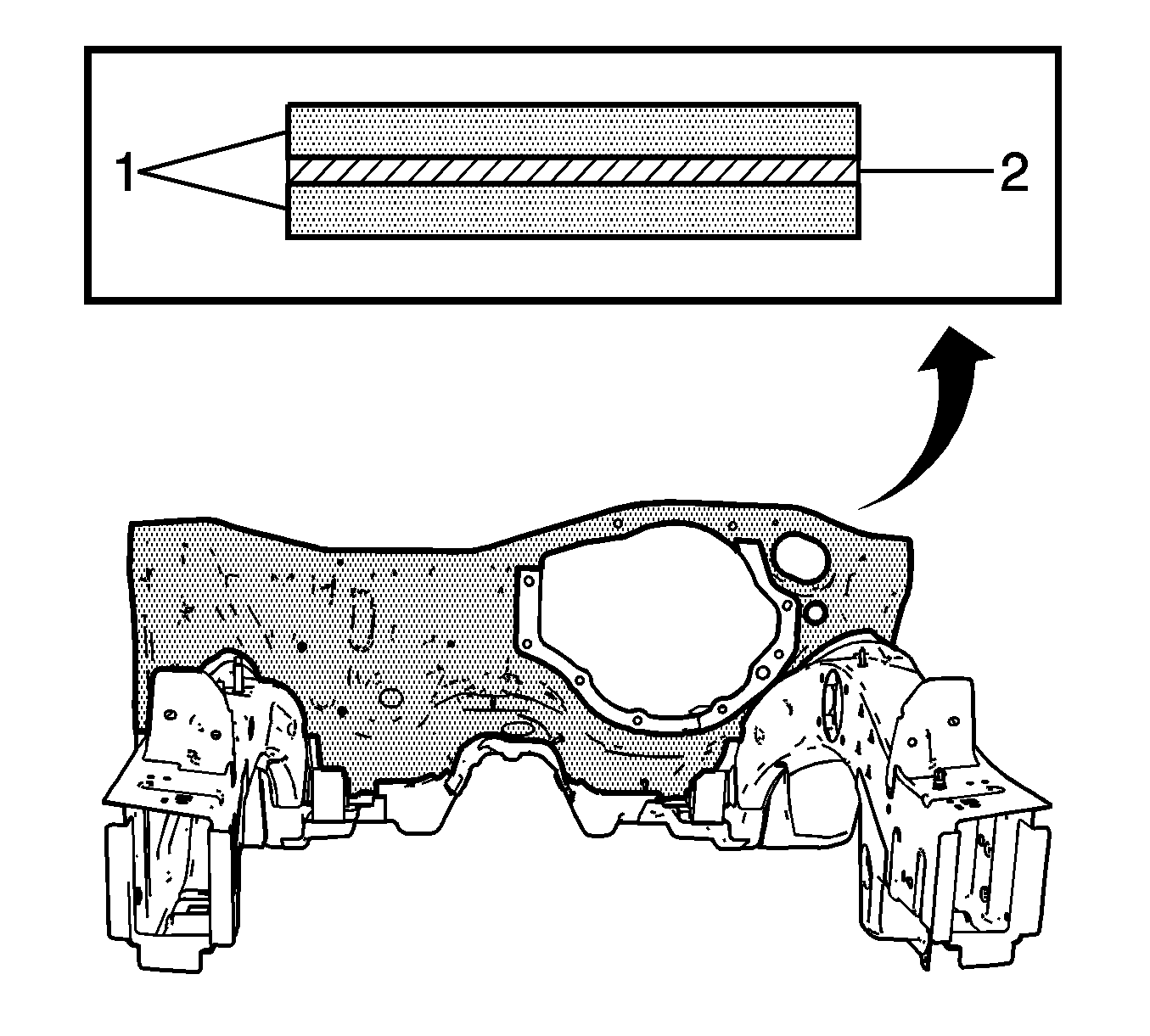
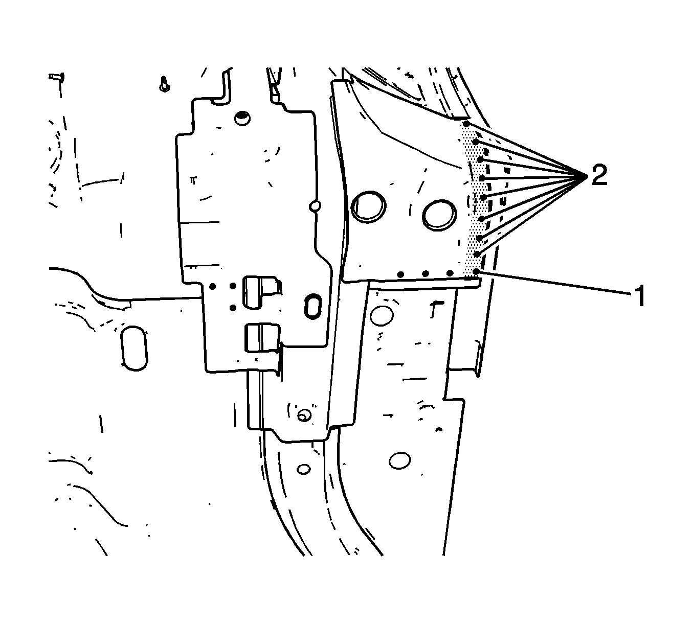
The front of the dash panel and the plenum lower are formed from laminated steel. This steel is constructed by bonding 2 pieces of cold rolled steel (1) with a viscoelastic layer of adhesive (2). MIG welding laminated steel does not meet GM Corporate standards for structural integrity. As an alternative, all factory welds will be replaced by using the rivet and adhesive bond method described in the installation portion of this procedure. The rivet and adhesive bond method must only be used in the areas as described in this procedure.
Removal Procedure
- Disable the SIR system. Refer to SIR Disabling and Enabling Zones in SIR.
- Disconnect the negative battery cable. Refer to Battery Negative Cable Disconnect/Connect Procedure in Engine Electrical.
- Remove all related panels and components.
- Repair as much of the damage as possible.
- Remove the sealers and the anti-corrosion materials from the repair area, as necessary. Refer to Anti-Corrosion Treatment and Repairs in Paint/Coatings.
- Using an 8-mm (5/16-in) spot weld remover, locate and drill out the factory welds on the weld flange connecting the lower inner rail to the dash panel.
- Using an 8-mm (5/16-in) spot weld remover, locate and drill out the factory welds on the weld flange connecting the lower outer rail to the dash panel.
- Using an 8-mm (5/16-in) spot weld remover, locate and drill out the factory welds on the weld flange connecting the lower rail to the outer dash panel.
- Using an 8-mm (5/16-in) spot weld remover, locate and drill out the factory welds on the weld flange connecting the lower rail to the dash panel.
- Locate and drill out the remaining factory welds on the rail.
- Remove the section of frame by applying heat. Pry to detach the adhesive along the bonding surface.
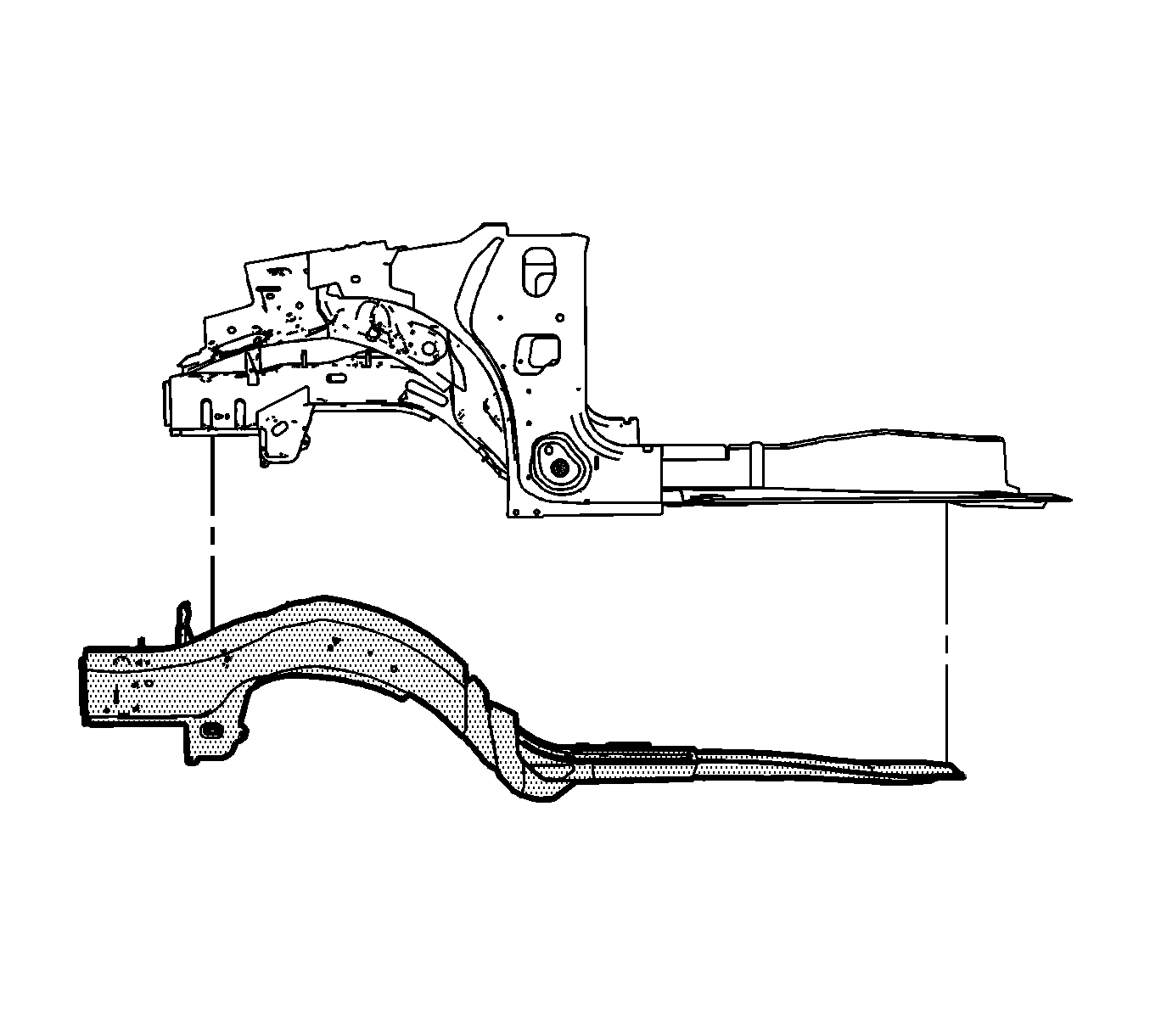
- Remove the full damaged rail.
Caution: Refer to Approved Equipment for Collision Repair Caution in Cautions and Notices.
Important: The full rail service part is replaced at factory seams.
Caution: Refer to Collision Sectioning Caution in Cautions and Notices.
Important: Note the number and location of the factory welds for installation of the full rail service part.
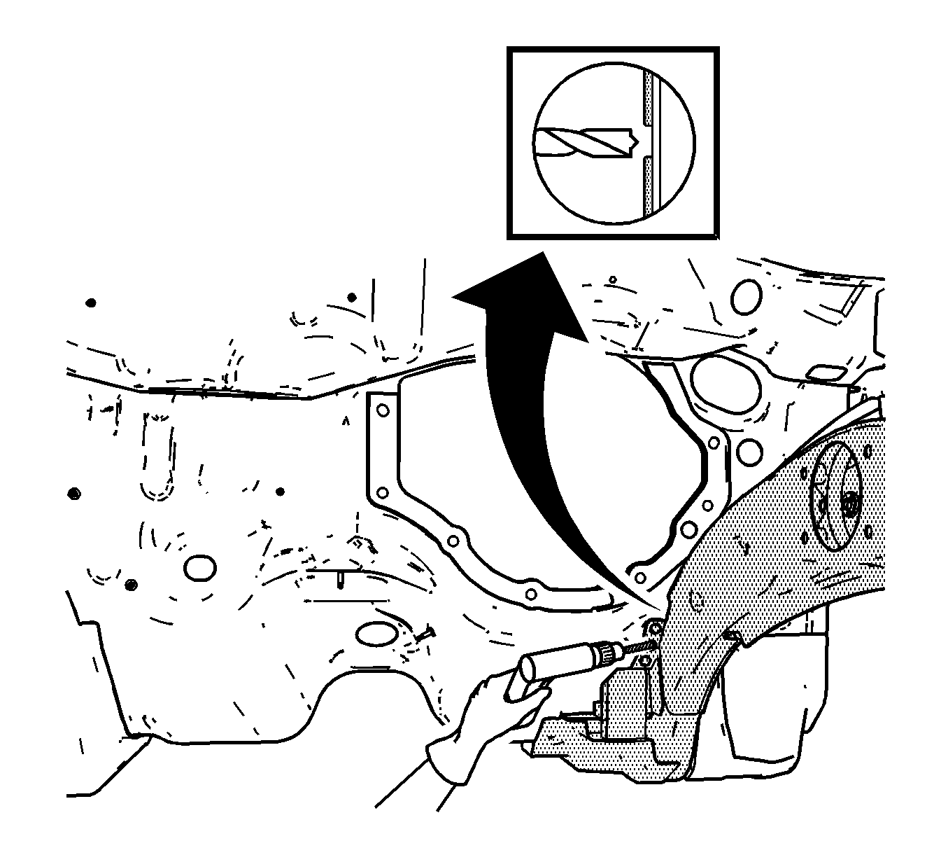
Important: Drill through the rail flange only. Do NOT drill into the dash panel or the inner reinforcements.
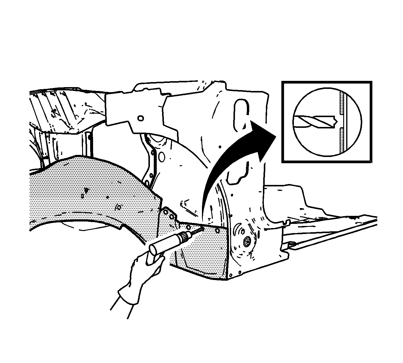
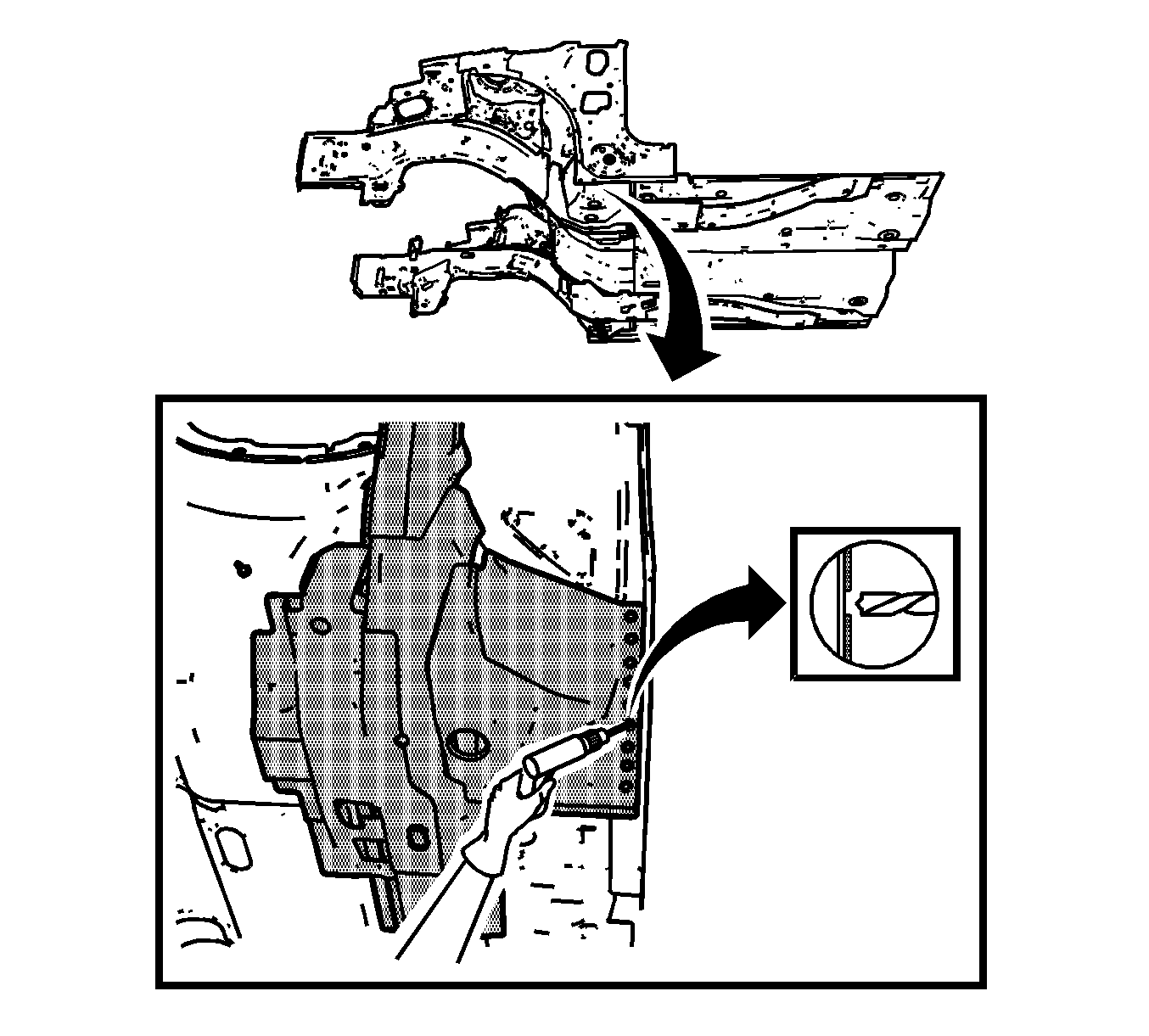
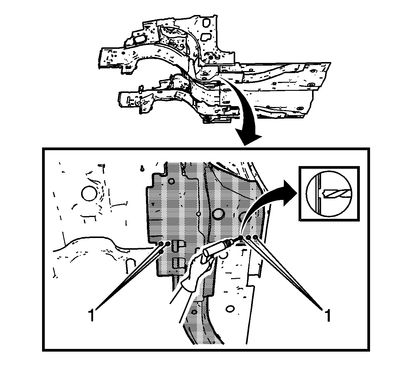
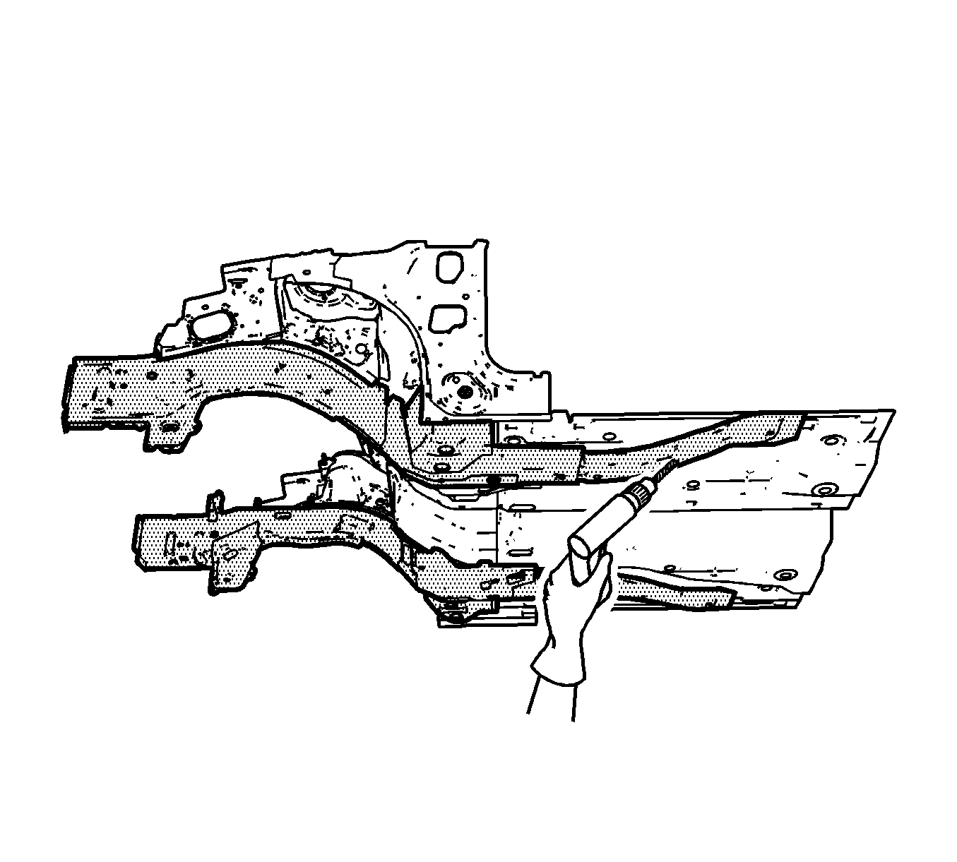
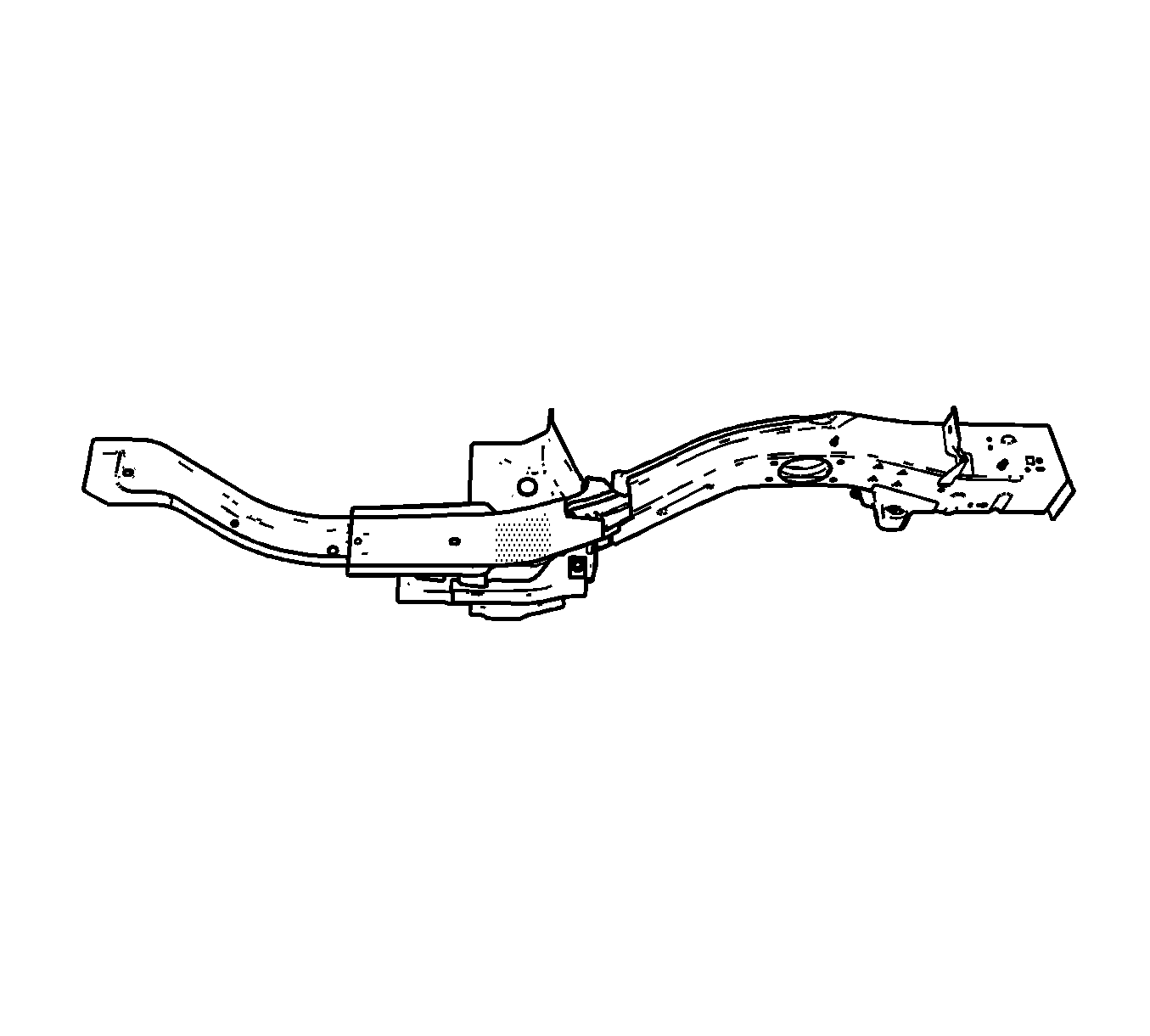

Installation Procedure
- Position the service rail to the vehicle using 3-dimensional measuring equipment.
- Clamp the service rail in place.
- Using a 7-mm (17/64-in) bit, drill the rivet attachment holes through the lower inner rail and the dash panel in the exact locations as noted from the factory rail.
- Using a 7-mm (17/64-in) bit, drill the rivet attachment holes through the lower outer rail and the dash panel in the exact locations as noted from the factory rail.
- Using a 7-mm (17/64-in) bit, drill the rivet attachment holes through the lower rail and the dash panel in the exact locations as noted from the factory rail.
- Remove the service rail.
- Drill 8-mm (5/16-in) plug weld holes in the service rail, as necessary, in the remaining locations noted from the original rail.
- Prepare the plug weld mating surfaces, as necessary.
- Apply 3M® Weld-Thru Coating, P/N 05913, or equivalent, to the plug weld mating surfaces.
- Prepare the bond mating areas by grinding to bare steel the lower inner rail and the dash panel mating surfaces. Do NOT damage the corners or thin the metal during the grinding process.
- Prepare the bond mating areas by grinding to bare steel the lower outer rail and the dash panel mating surfaces. Do NOT damage the corners or thin the metal during the grinding process.
- Prepare the bond mating areas by grinding to bare steel the surface of the lower rail and the dash panel mating surfaces. Do NOT damage the corners or thin the metal during the grinding process.
- Prepare the bond mating areas by grinding to bare steel the lower rail and the floor panel mating surfaces. Do NOT damage the corners or thin the metal during the grinding process.
- Clean the mating surfaces.
- Apply a 3-6 mm (1/8-1/4 in) bead of metal panel bonding adhesive, GM P/N 12378567 (Canadian P/N 88901675), or equivalent, to both of the mating surfaces.
- Apply a 3-6 mm (1/8-1/4 in) bead of metal panel bonding adhesive, GM P/N 12378567 (Canadian P/N 88901675), or equivalent, to the lower inner rail and the dash panel mating surfaces.
- Apply a 3-6 mm (1/8-1/4 in) bead of metal panel bonding adhesive GM P/N 12378567, (Canadian P/N 88901675), or equivalent, to the lower outer rail and the dash panel mating surfaces.
- Apply a 3-6 mm (1/8-1/4 in) bead of metal panel bonding adhesive, GM P/N 12378567 (Canadian P/N 88901675), or equivalent, to the lower rail and the floor panel mating surfaces.
- Using a small acid brush, spread a coat of adhesive to the lower inner rail and the dash panel mating surfaces. Cover all of the bare metal to ensure corrosion protection.
- Using a small acid brush, spread a coat of adhesive to the lower outer rail and the dash panel mating surfaces. Cover all of the bare metal to ensure corrosion protection.
- Using a small acid brush, spread a coat of adhesive to the lower rail and the dash panel mating surfaces. Cover all of the bare metal to ensure corrosion protection.
- Position the service rail to the vehicle using 3-dimensional measuring equipment.
- Clamp the rail in place.
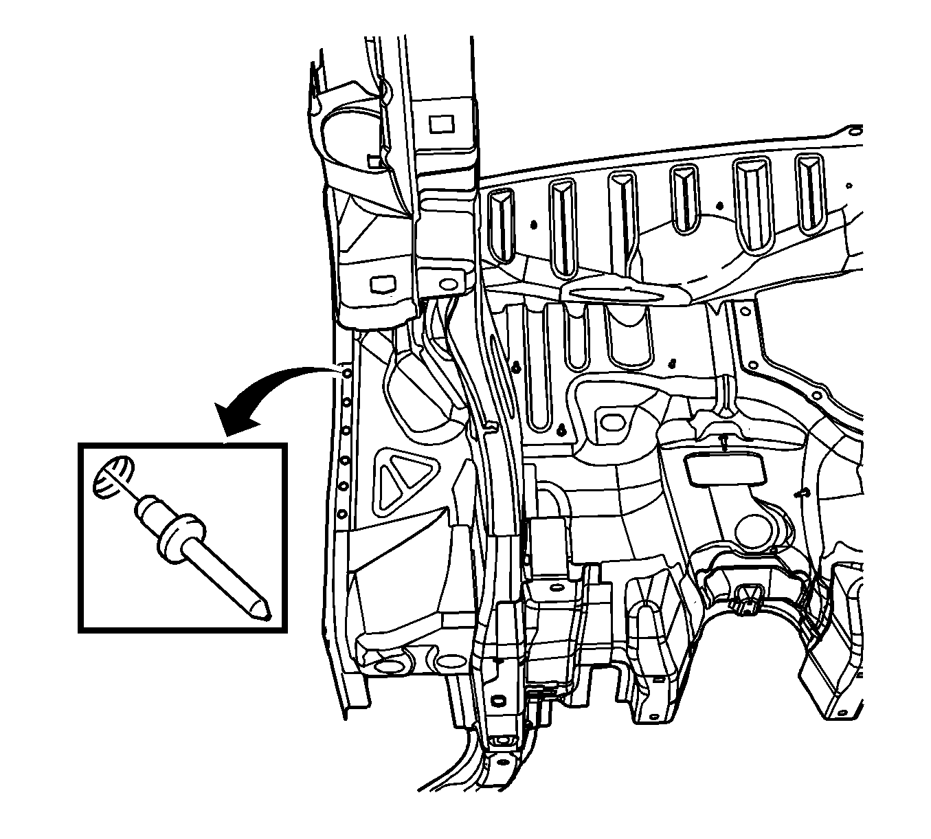
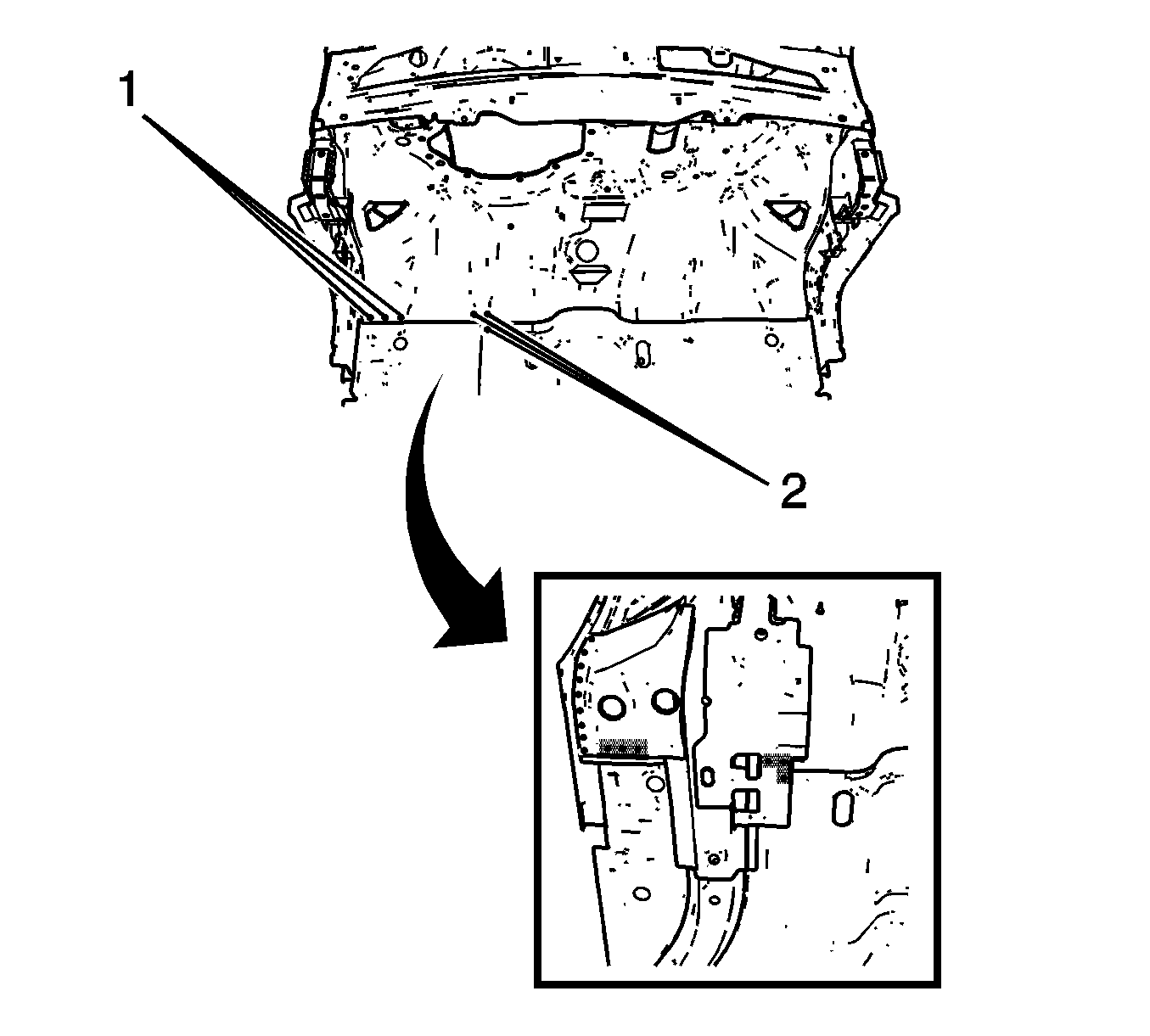
- Install the 9-mm (11/32-in) long rivets (1) and the 14-mm (17/32-in) long rivets (2) to the lower inner and outer rail so that the rivet head contacts the passenger compartment side of the dash panel.
- Install the 9-mm (11/32-in) long rivets (1) and the 14-mm (17/32-in) long rivets (2) to the lower inner and the outer dash panel so that the rivet head contacts the rail side.
- Install the 9-mm (11/32-in) long rivets (1) and the 14-mm (17/32-in) long rivets (2) to the lower rail and the dash panel so that the rivet head contacts the passenger compartment side of the dash panel.
- Remove the excess adhesive from the rail area.
- Plug weld the remaining holes accordingly.
- Clean and prepare all of the welded surfaces.
- Apply the sealers and anti-corrosion materials to the repaired area, as necessary. Refer to Anti-Corrosion Treatment and Repair in Paint/Coatings.
- Paint the repaired area. Refer to Basecoat/Clearcoat Paint Systems in Paint/Coatings.
- Install all of the related panels and components.
- Connect the negative battery cable. Refer to Battery Negative Cable Disconnect/Connect Procedure in Engine Electrical.
- Enable the SIR system. Refer to SIR Disabling and Enabling Zones in SIR.

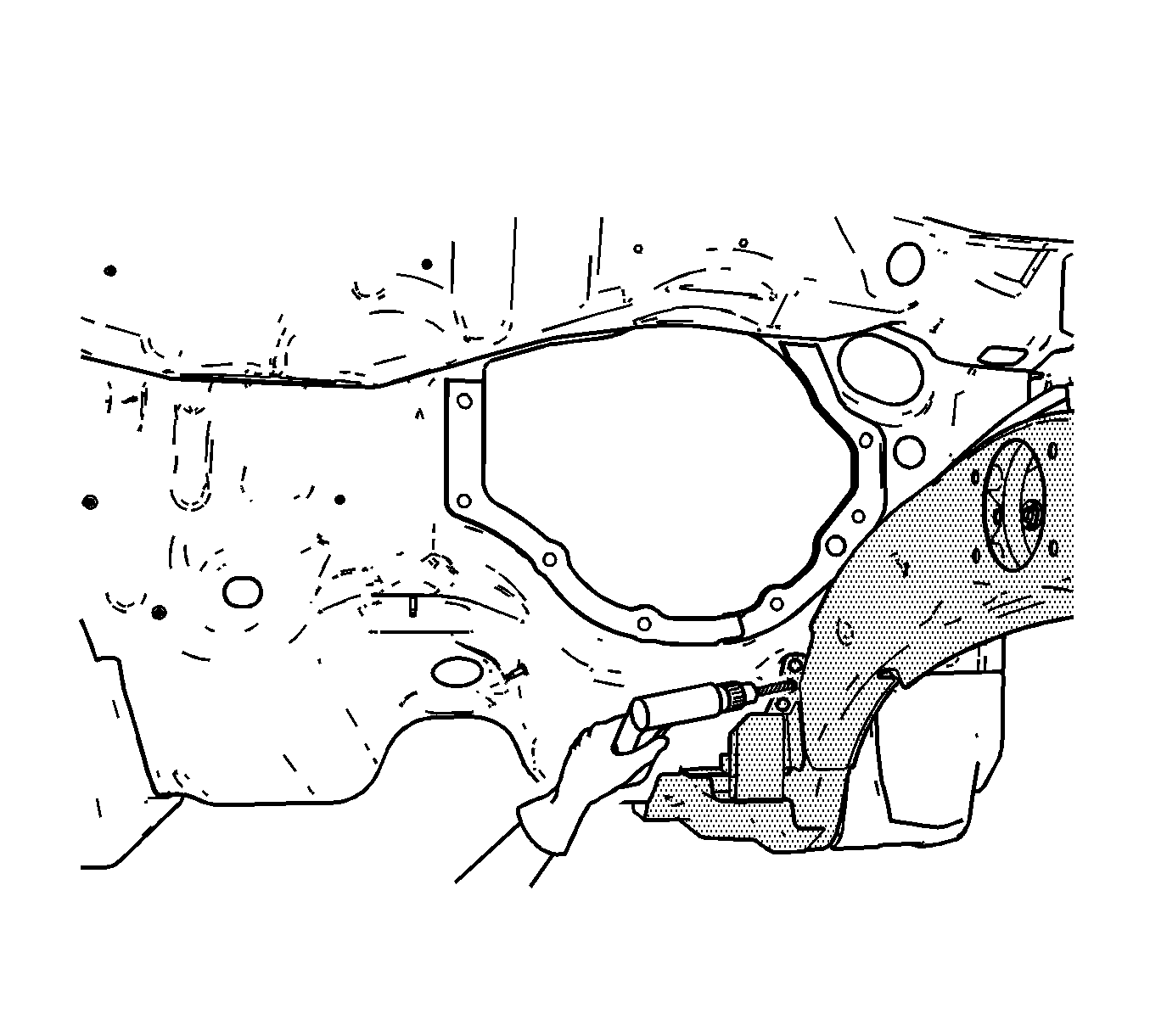
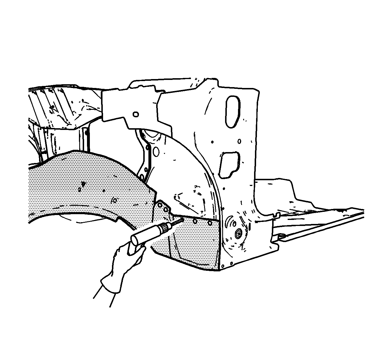
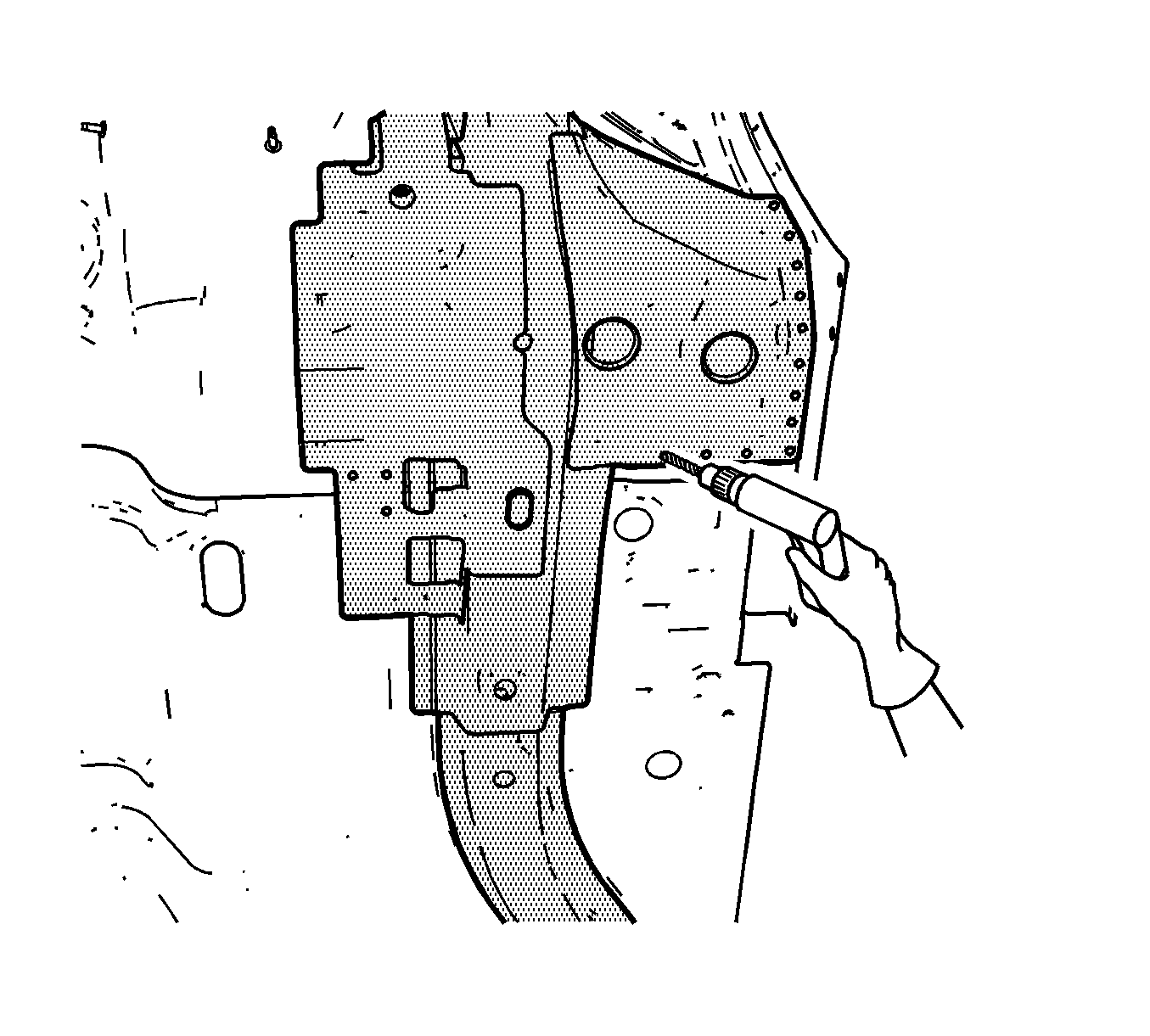
Important: If the location of the original plug weld holes cannot be determined, or if the structural weld-through adhesive is present, space the plug weld holes every 40 mm (1.5 in) apart.
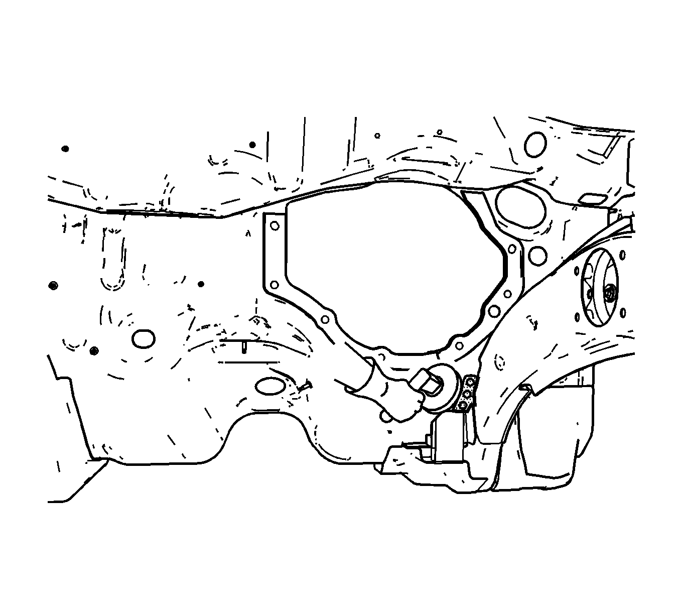
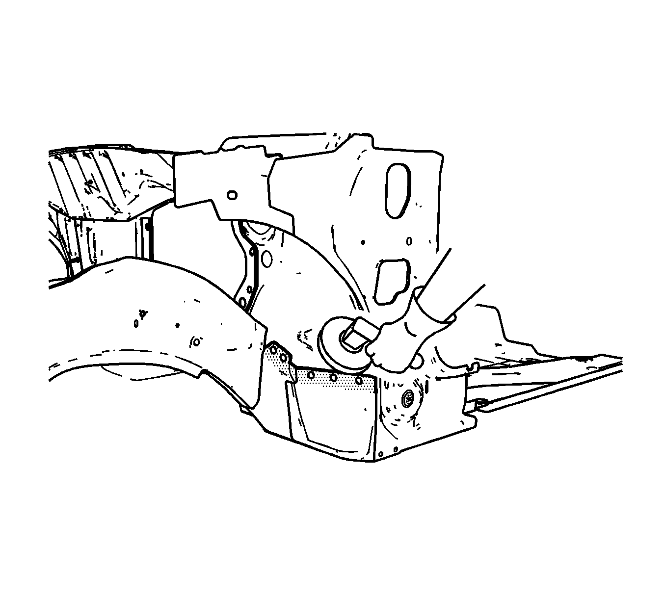
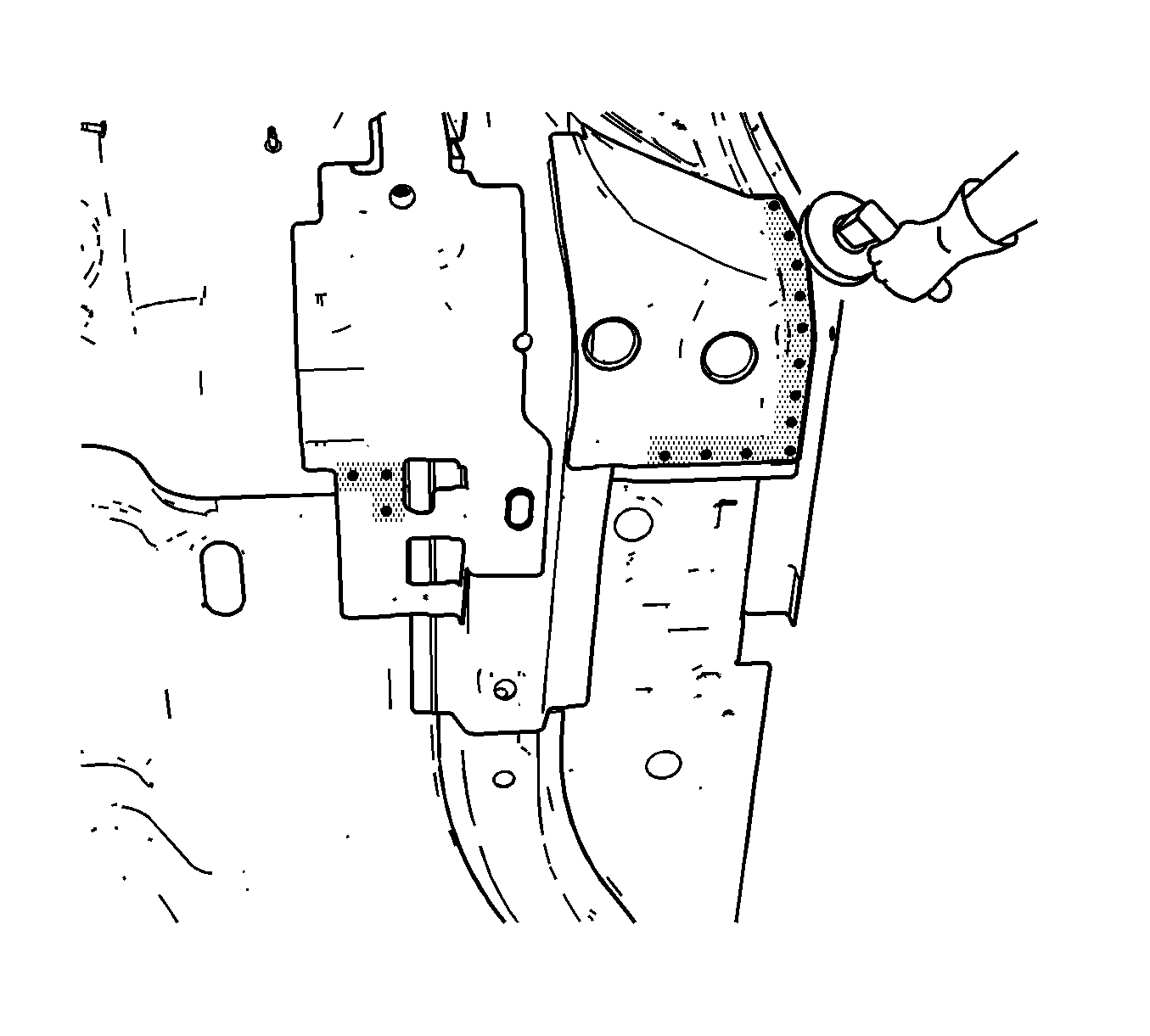

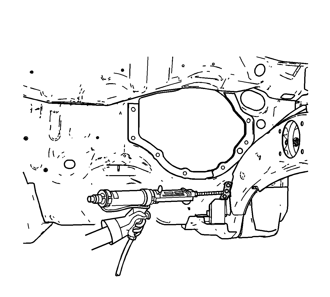
Important: The adhesive has a 40-50 minute working time. Do NOT allow the adhesive to cure prior to installing the service rail.
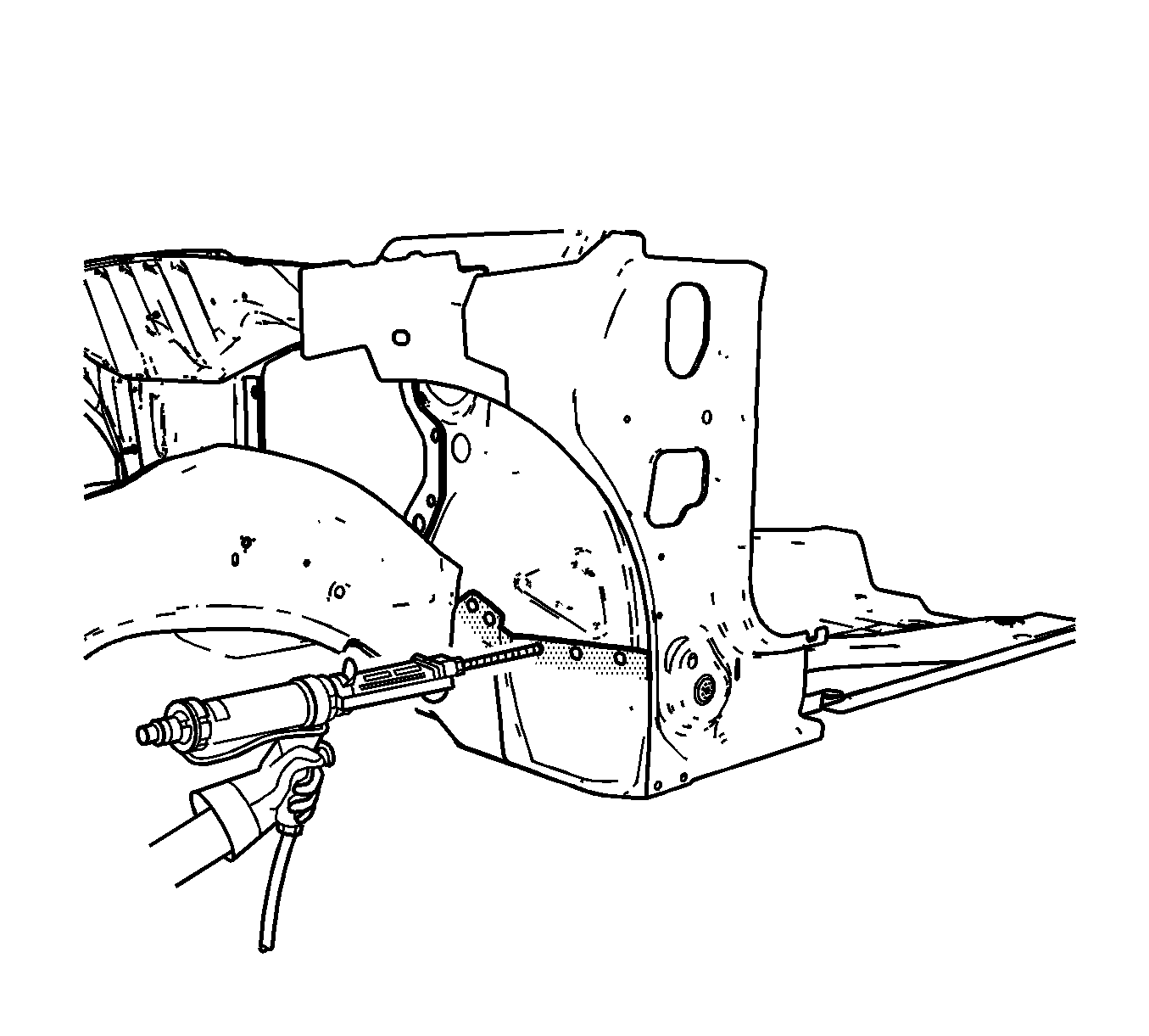
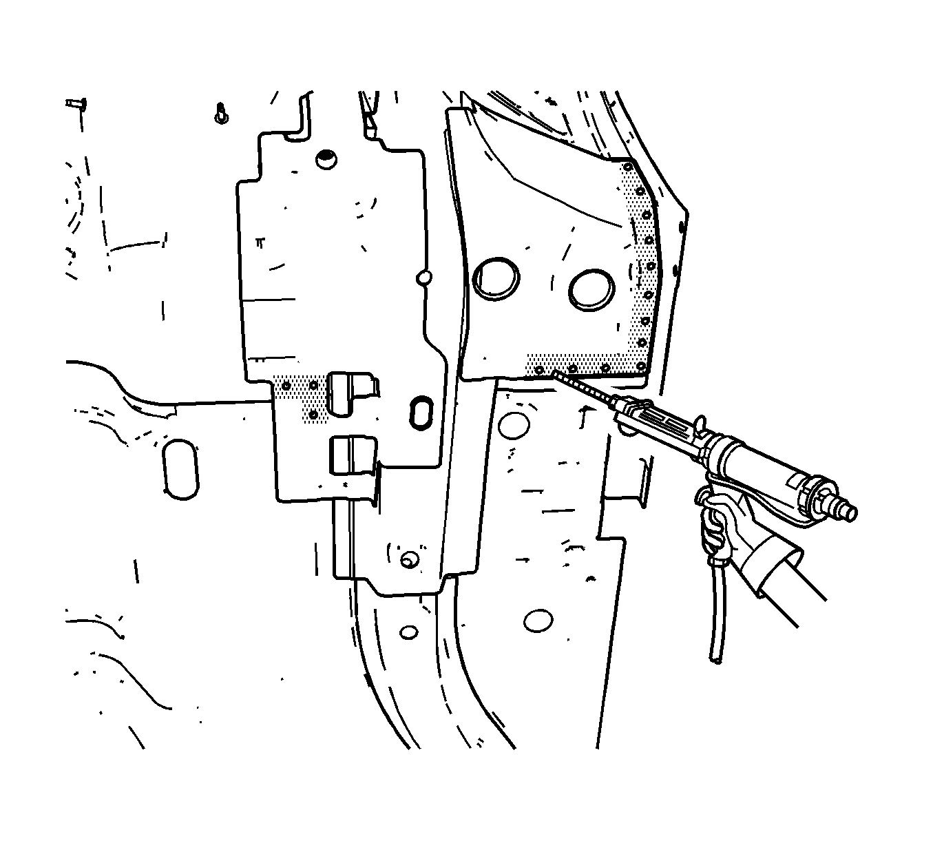
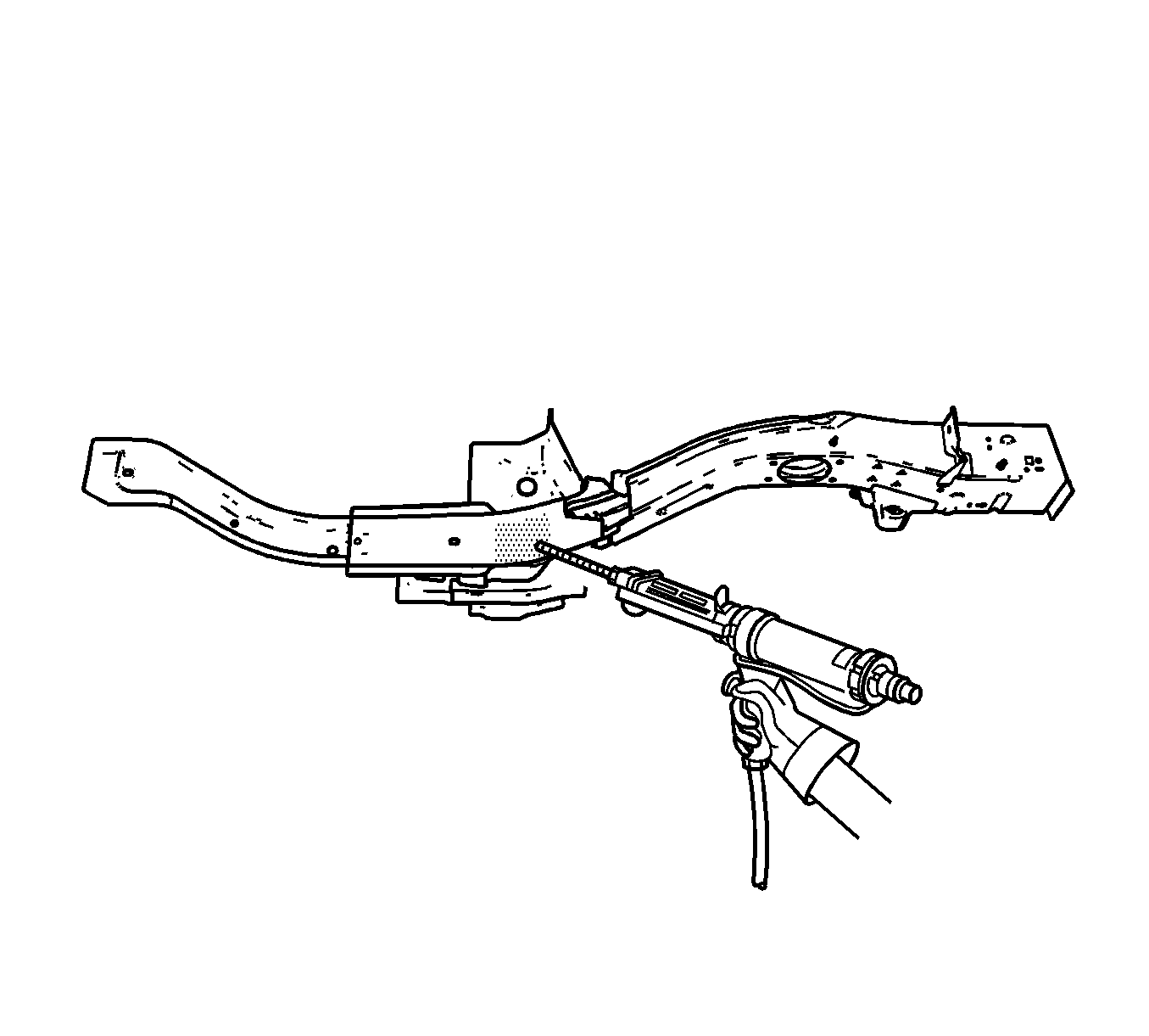
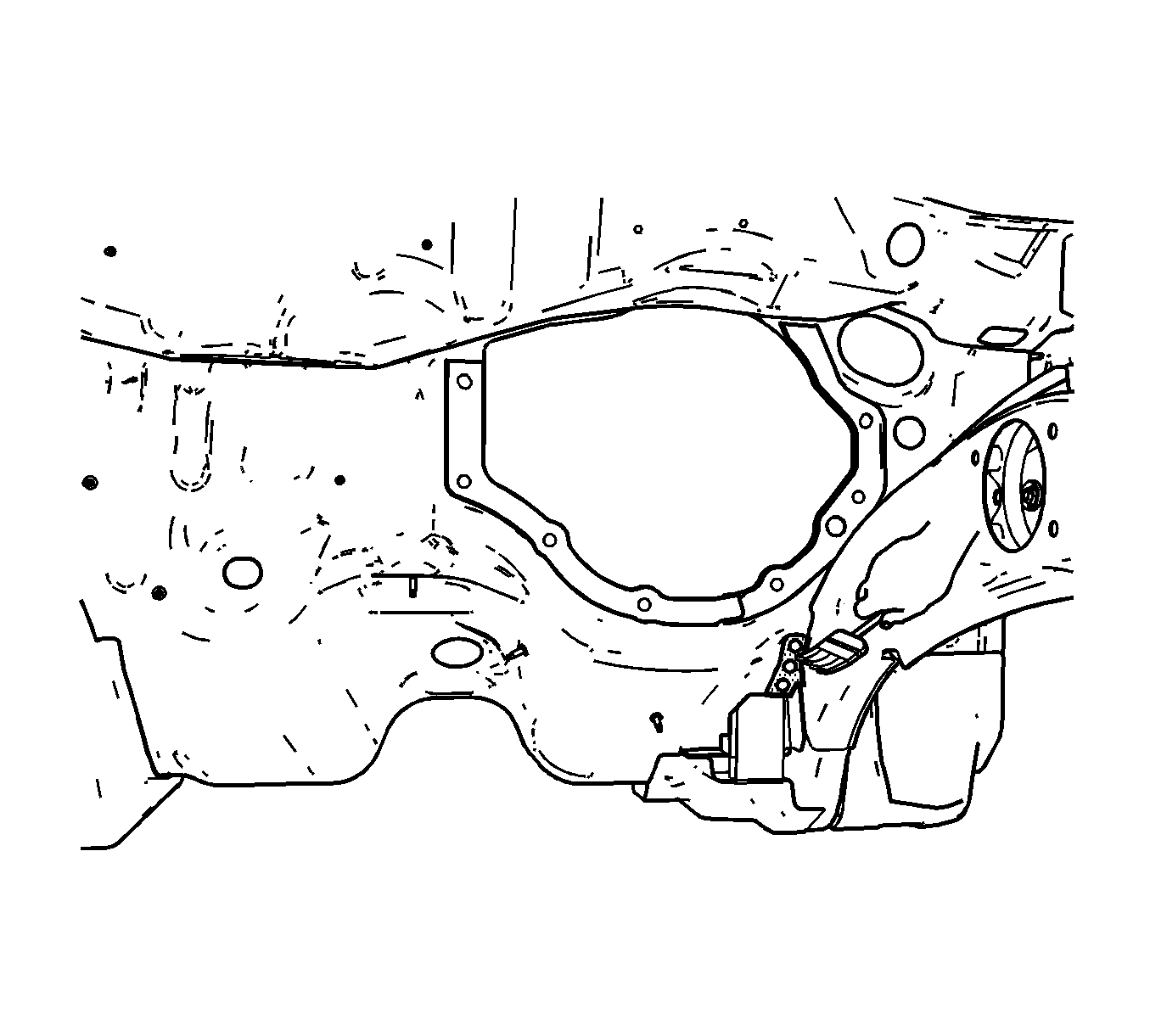
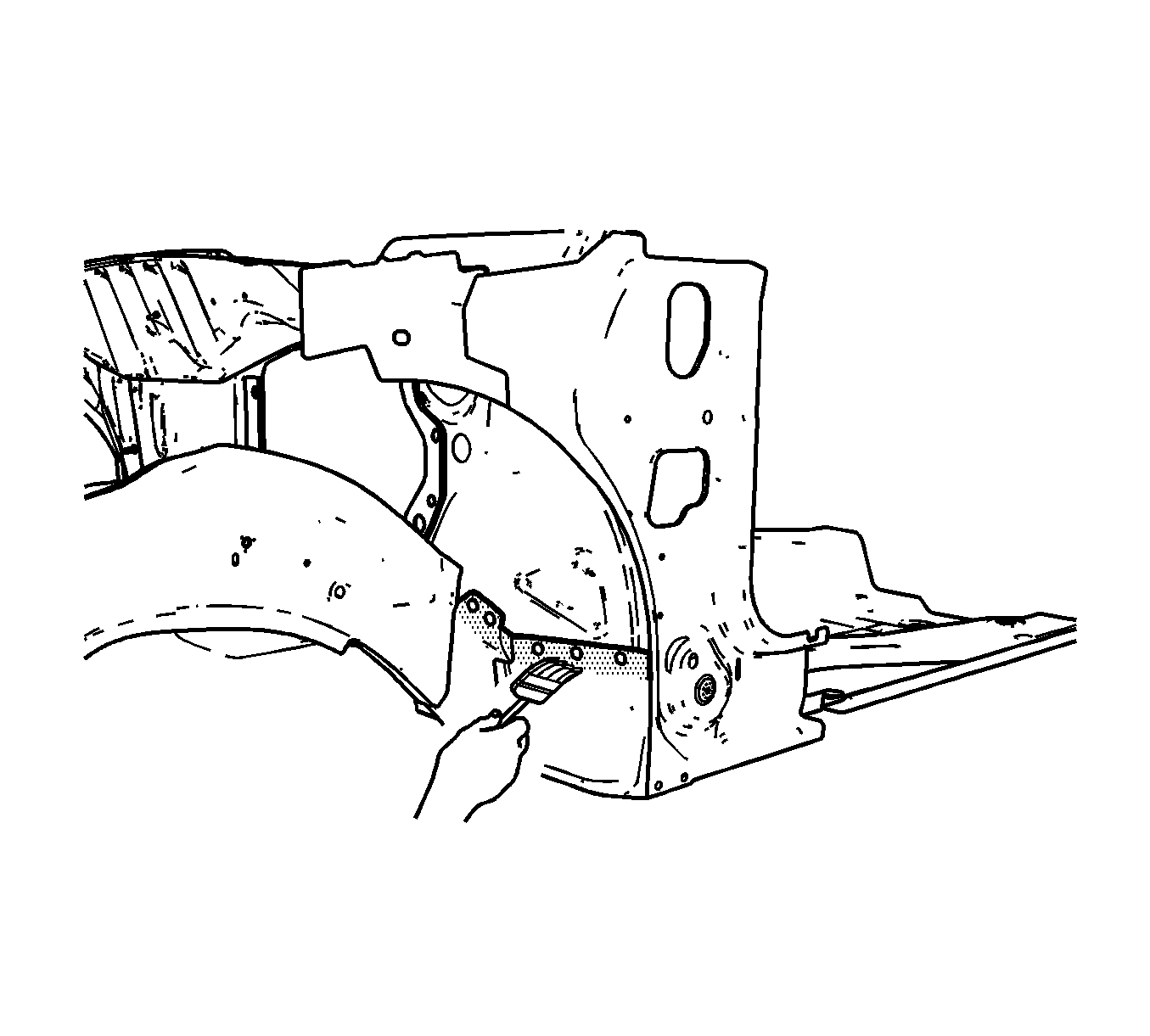
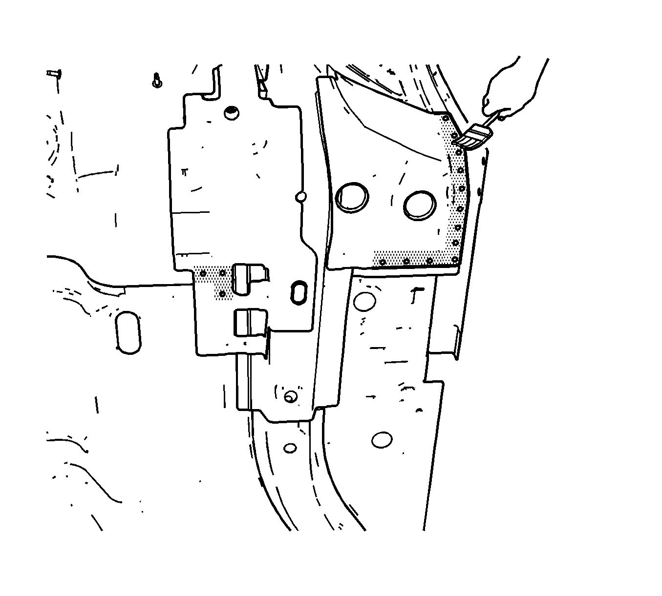

Important: Do NOT pull the rail off of the dash after adhesion. To align the parts, slide the rail against the front of the dash.
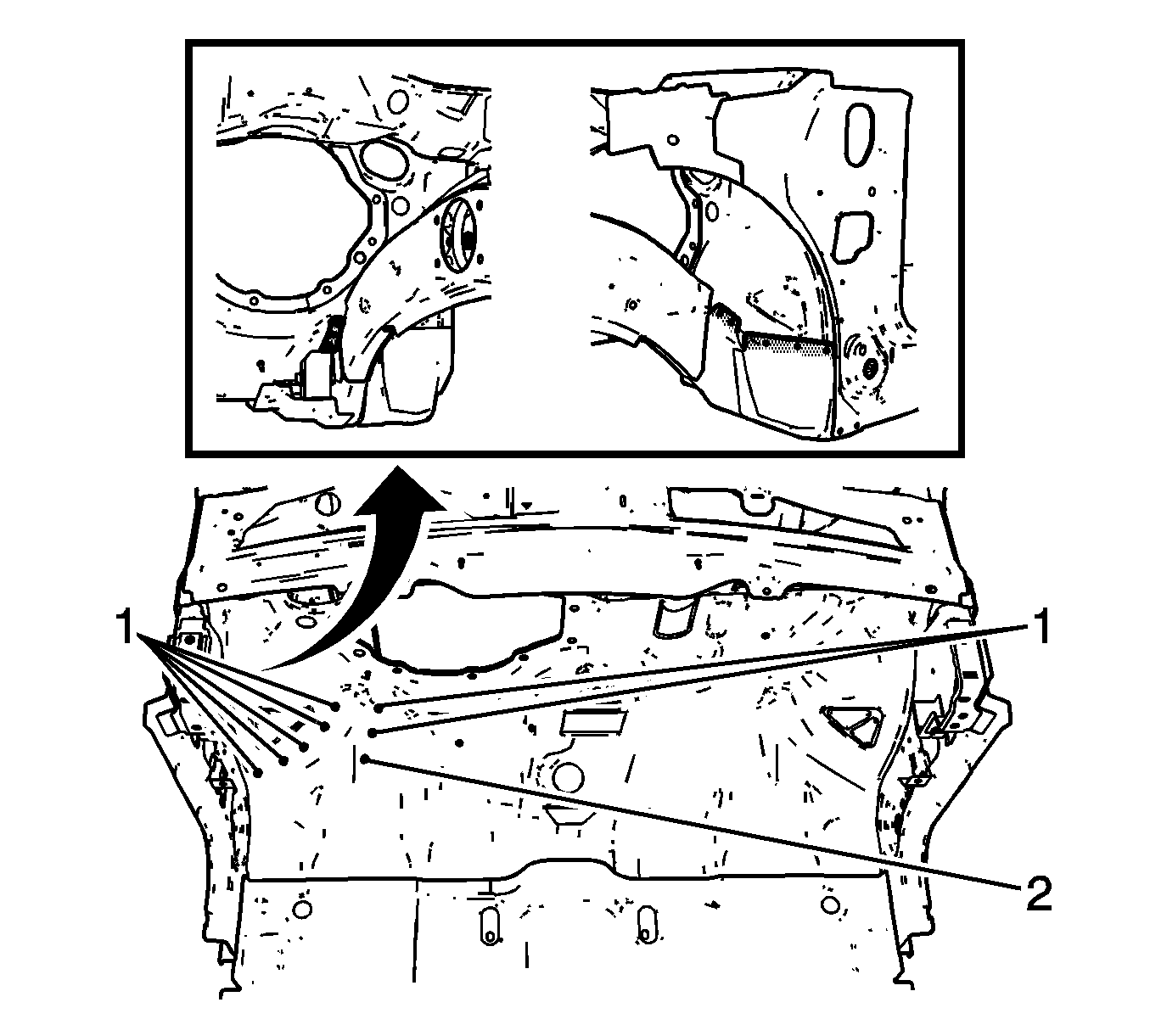
Important: Verify proper positioning of the service rail prior to riveting and welding.
Wheelhouse Replacement - Front

The front of the dash panel and plenum lower are formed from laminated steel. This steel is constructed by bonding 2 pieces of cold rolled steel with a viscoelastic layer of adhesive. MIG welding laminated steel does not meet GM Corporate standards for structural integrity. As an alternative, all factory welds may be replaced by using the rivet and adhesive bond method described in the installation portion of this procedure. The rivet and adhesive bond method must only be used in the areas described in this procedure.
Important: Failure to follow this procedure will compromise the structural integrity of the vehicle.
Removal Procedure
- Disable the SIR system. Refer to SIR Disabling and Enabling Zones in SIR.
- Disconnect the negative battery cable. Refer to Battery Negative Cable Disconnect/Connect Procedure in Engine Electrical.
- Remove the sealers and anti-corrosion materials from the repair area, as necessary. Refer to Anti-Corrosion Treatment and Repair in Paint and Coatings.
- Visually inspect the damaged area. Repair as much of the damage as possible. Refer to Dimensions - Body.
- Using an 8 mm (5/16 In) spot weld remover, locate and drill out the factory welds on the weld flange connecting the wheelhouse to the dash panel.
- Using an 8 mm (5/16 In) spot weld remover, locate and drill out the factory welds on the weld area that connects the top of the wheelhouse strut cap to the lower plenum.
- Locate and drill out all remaining factory welds.
- Remove the front wheelhouse from the vehicle.
Caution: Refer to Approved Equipment for Collision Repair Caution in Cautions and Notices.
Important: The upper strut mounting surface is a dimensionally critical area and 3-dimensional measuring equipment should be used to locate the front wheelhouse assembly. The front wheelhouse can be serviced as a complete assembly for both the left and right wheelhouses. A wheelhouse front panel is also available to service separately on the left or the right sides.
Important: Be sure to inspect the front of the cowl and dash panel for damage. If the metal surface is damaged, the cowl panel must be repaired to restore the structural integrity of the vehicle.
Important: Drill through the wheelhouse flange only. Do not drill into the dash panel.
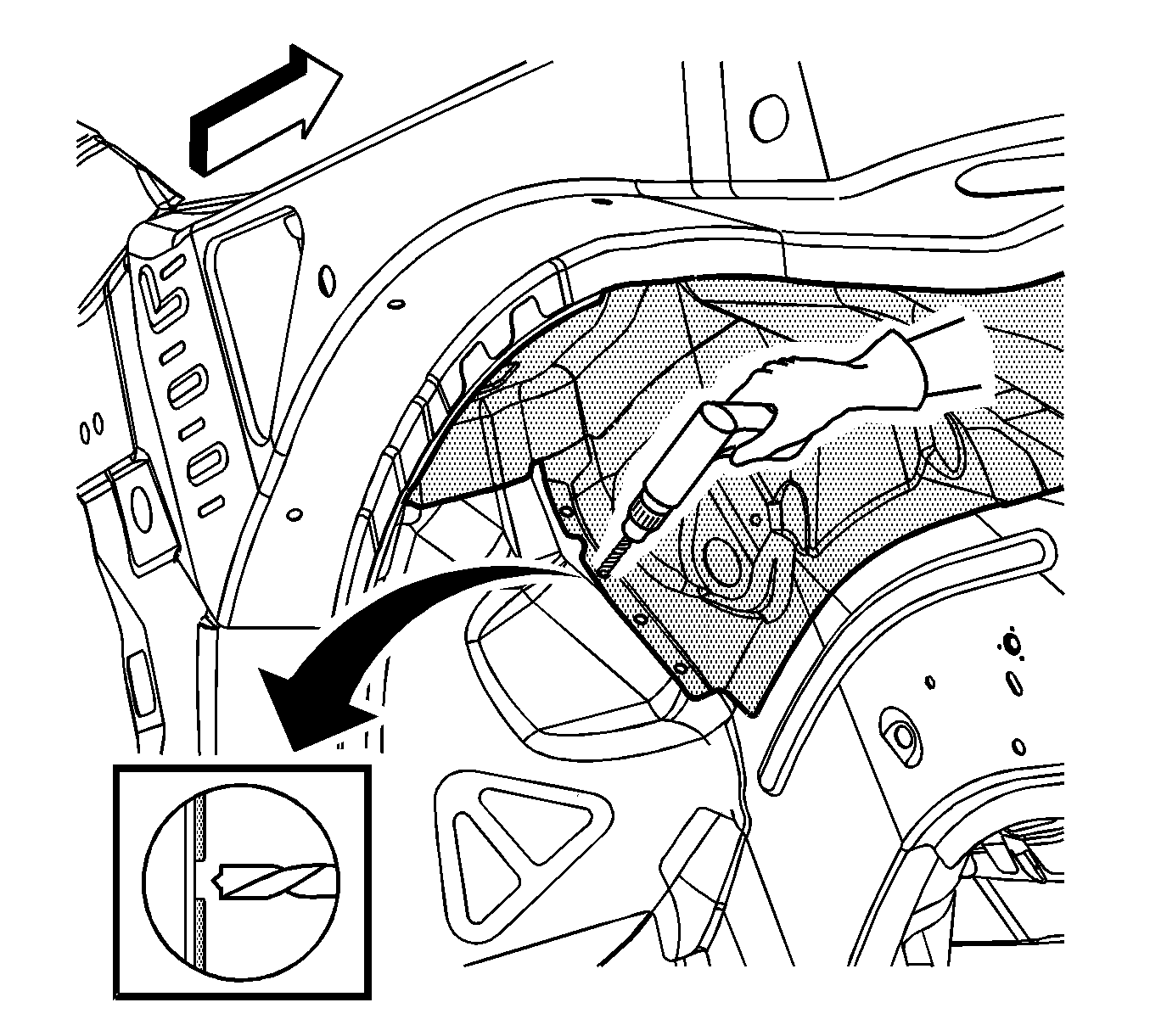
Important: Drill through the wheelhouse strut cap only. Do not drill into the plenum lower.
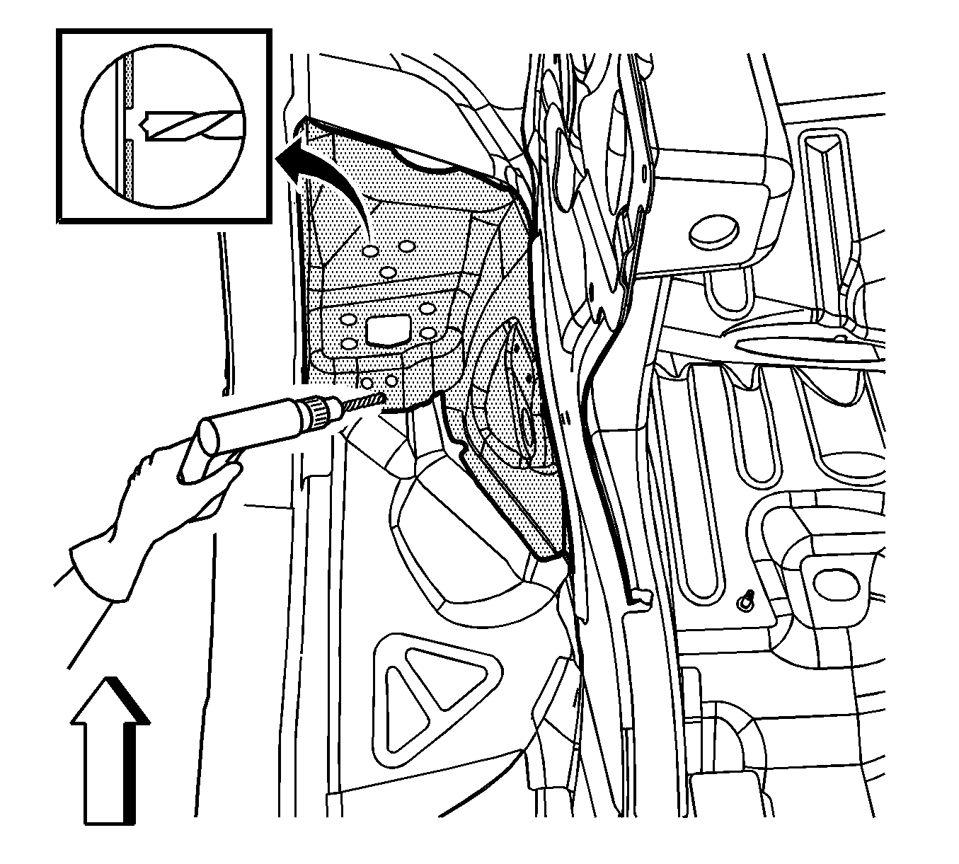
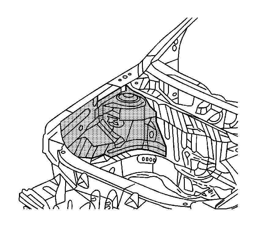
Important: Note the number and location of welds for installation of the front wheelhouse.
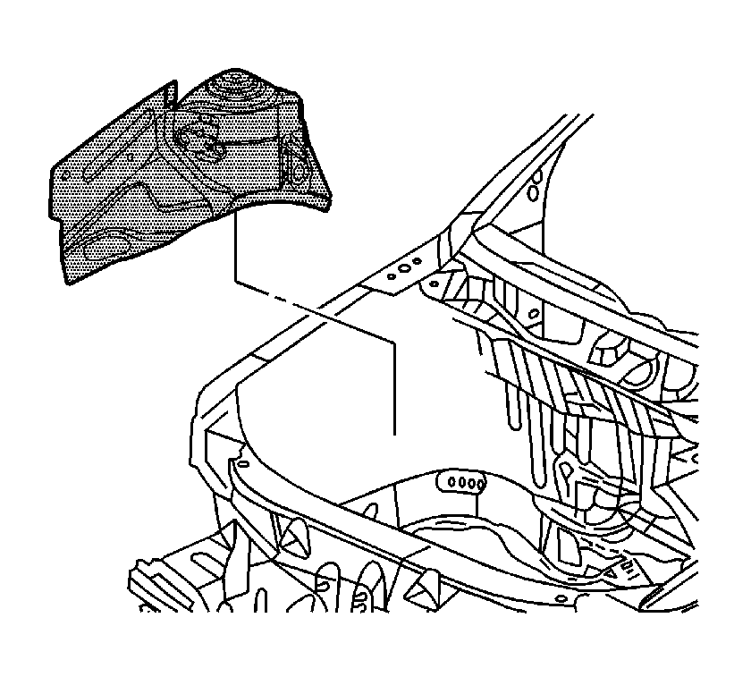
Installation Procedure
- Position the service front wheelhouse in the vehicle using 3-dimensional measuring equipment. Clamp the wheelhouse in place.
- Using a 7 mm (17/64 in) bit, drill the rivet attachment holes through the service wheelhouse and the dash and the lower plenum in the locations as noted from the factory wheelhouse.
- Remove the service front wheelhouse.
- Drill 8 mm (5/16 in) plug weld holes as necessary in the locations noted from the original assembly.
- Prepare the MIG weld mating surfaces as necessary.
- Apply 3M® Weld-Thru Coating, P/N 05916, or equivalent, to all MIG weld mating surfaces. This includes all welds not attached to the dash or the lower plenum.
- Prepare the bonding mating areas by grinding to bare steel the surface of the body mating and at the service wheelhouse flanges.
- Apply a 3-6 mm (1/8-1/4 in) bead of metal panel bonding adhesive, P/N 12378567 (Canadian P/N 88901675), or equivalent, to the mating surfaces of the dash and lower plenum, and the wheelhouse service panel.
- Using a small acid brush, spread a coating of adhesive on the mating surfaces. Cover all of the bare metal to ensure corrosion protection.
- Position the service front wheelhouse to the vehicle using 3-dimensional measuring equipment. Clamp the front wheelhouse in place.
- Install the 9 mm (11/32 in) long rivets so that the rivet head contacts the wheelhouse cap bottom side.
- Install the 9 mm (11/32 in) long rivets so that the rivet head contacts the dash panel.
- Remove the excess adhesive from the front wheelhouse bond rivet area.
- Plug weld accordingly.
- Clean and prepare all of the welded surfaces.
- Apply the sealers and anti-corrosion materials to the repair area, as necessary. Refer to Anti-Corrosion Treatment and Repair in Paint and Coatings.
- Paint the repaired area. Refer to Basecoat/Clearcoat Paint Systems in Paint and Coatings.
- Install all related panels and components.
- Connect the negative battery cable. Refer to Battery Negative Cable Disconnect/Connect Procedure in Engine Electrical.
- Enable the SIR system. Refer to SIR Disabling and Enabling Zones in SIR.
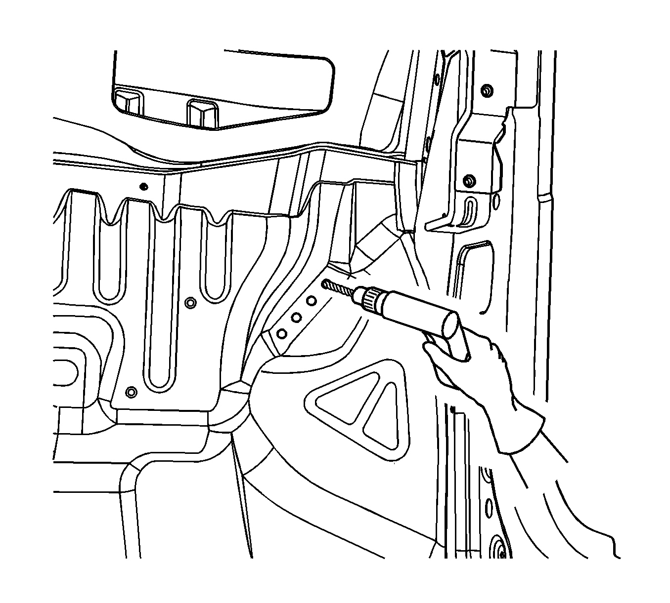

Important: If the location of the original plug weld holes can not be determined, space the plug weld holes every 40 mm (1 1/2 in) apart.
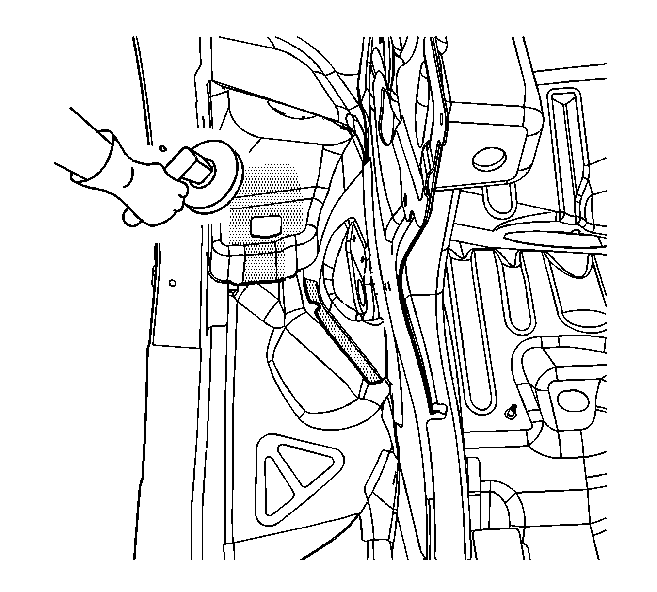
Important: Do not damage the corners on the thin metal during the grinding process.
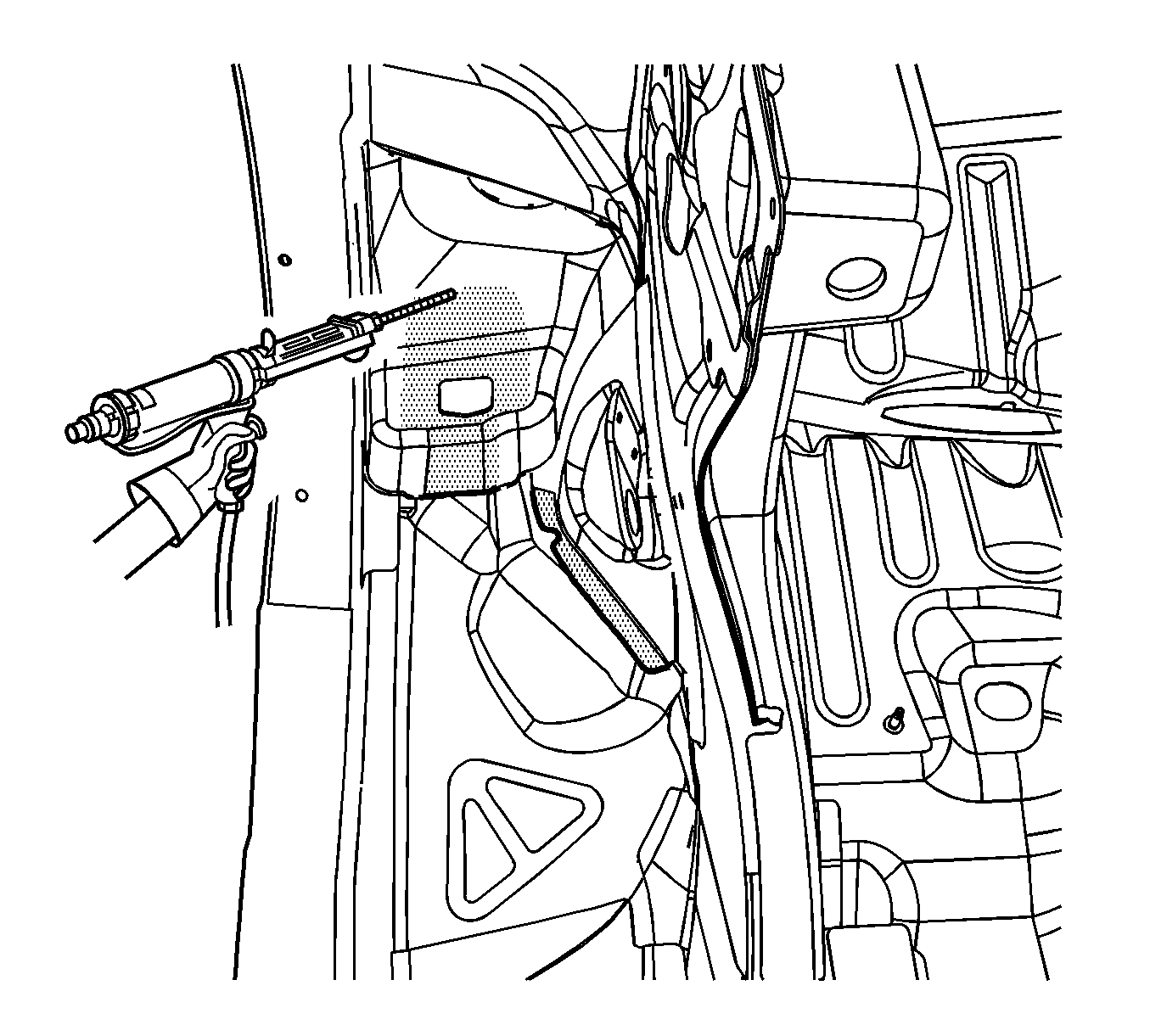
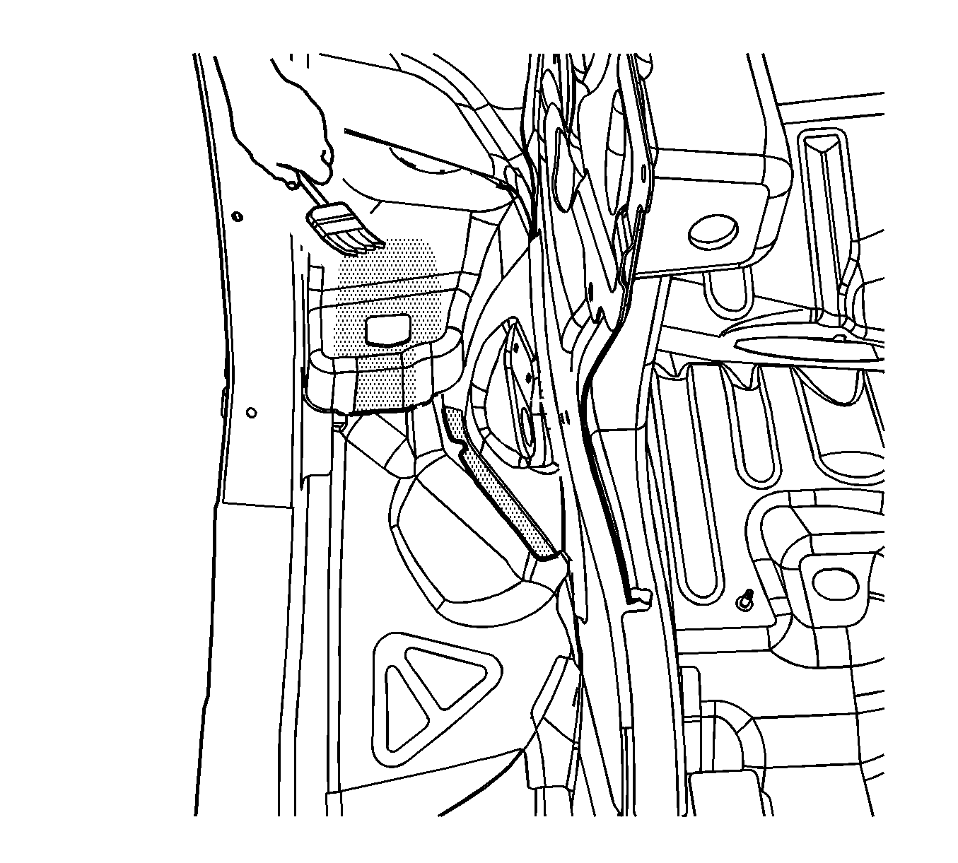
Important: Do not pull the front wheelhouse off of the dash on the plenum after adhesion. To align the parts, slide the front wheelhouse against the front of the dash.
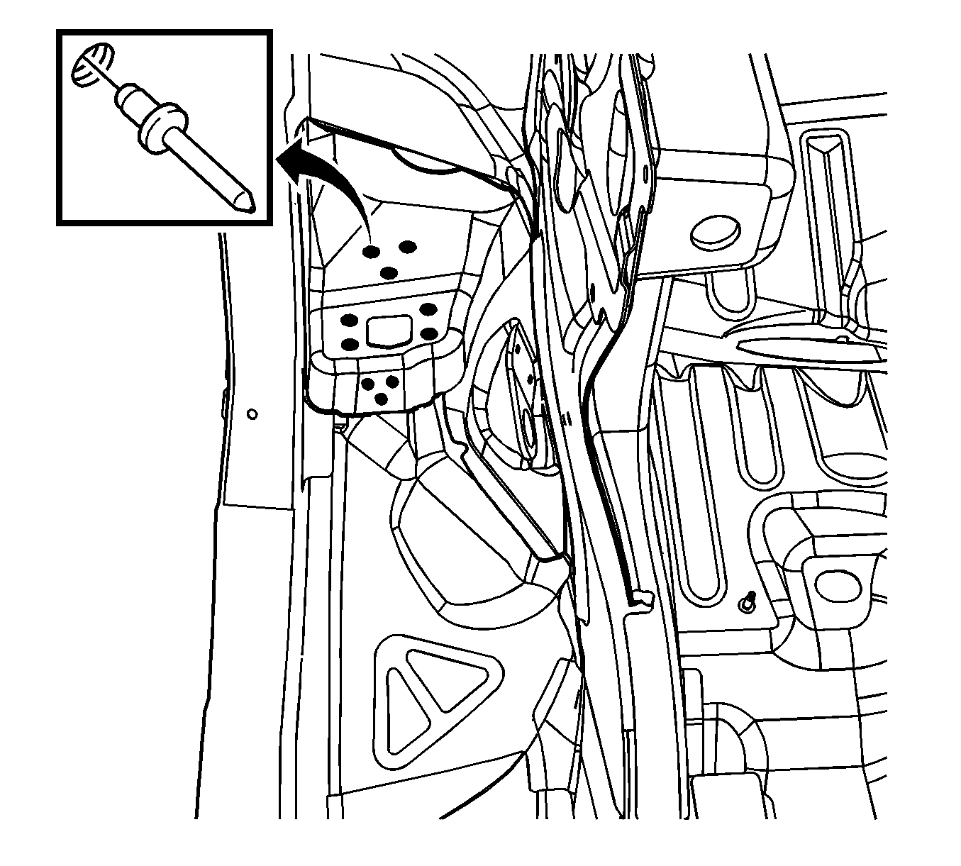
Important: Verify the proper positioning of the service front wheelhouse prior to riveting and welding.
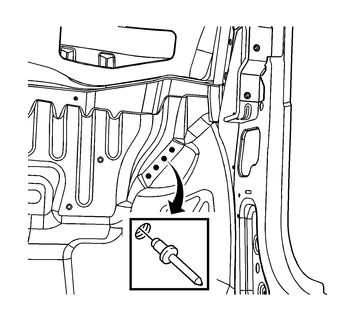

Parts Information
Important: These kits also contain an instruction sheet and rivets.
Part Number | Description |
|---|---|
89025049 | Panel Kit, Frt W/H Frt (LH) |
89025050 | Panel Kit, Frt W/H Frt (RH) |
89025052 | Rail Kit, F/Cmpt Side (RH) |
89025053 | Rail Kit, F/Cmpt Side (LH) |
89025057 | Panel Kit, Body H/Plr Inner (LH) |
89025058 | Panel Kit, Body H/Plr Inner (RH) |
