- Install the connecting rod bearings. Use the proper size bearings.
| 1.1. | Install the bearing inserts into the connecting rod and the connecting rod cap. |
| 1.2. | Lubricate the connecting rod bearings with engine oil. |
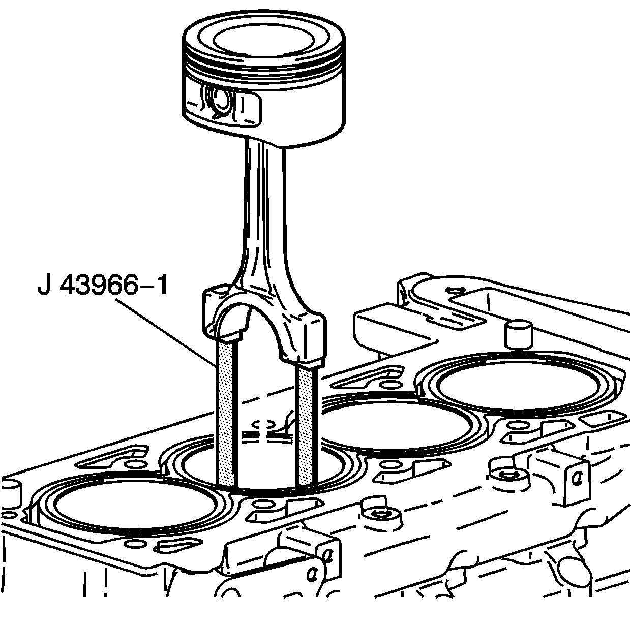
- Install the
J-43966-1
/
J 41742
into the connecting rod bolt holes. This protects the crankshaft journal during piston and connecting rod
installation.
- Install the piston and the connecting rod to the correct bore.
| 3.1. | Stagger each piston ring end gap equally around the piston. |
| 3.2. | Lubricate the piston and the piston rings with engine oil. |
| 3.3. | Install
J 43953
over the piston. Do not disturb the piston ring end gap location. |
| 3.4. | The piston must be installed so that the mark on the top of the piston faces the front of the engine. |
| 3.5. | Place the piston in its matching bore. |
| 3.6. | Tap the piston into its bore with a hammer handle. Guide the connecting rod to the connecting rod journal while tapping the piston into place. |
| 3.7. | Hold the
J 43953
against the engine block until all the rings have entered the cylinder bore. |
| 3.8. | Remove the connecting rod guides from the connecting rod bolt holes. |

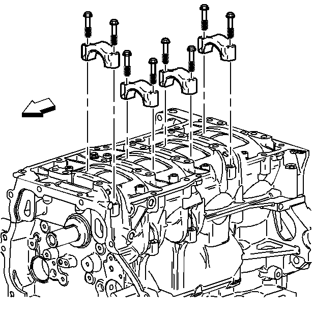
Important: Ensure that the connecting rod cap is properly oriented on the connecting rod.
- Install the connecting rod cap.
Notice: Use the correct fastener in the correct location. Replacement fasteners
must be the correct part number for that application. Fasteners requiring
replacement or fasteners requiring the use of thread locking compound or sealant
are identified in the service procedure. Do not use paints, lubricants, or
corrosion inhibitors on fasteners or fastener joint surfaces unless specified.
These coatings affect fastener torque and joint clamping force and may damage
the fastener. Use the correct tightening sequence and specifications when
installing fasteners in order to avoid damage to parts and systems.
- Install the connecting rod bolts. Always use new bolts.
Tighten
Tighten the connecting rod bolt nuts to 25 N·m (18 lb ft), plus 100 degrees using
J 36660-A
.
- Install the remaining connecting rods and piston assemblies.

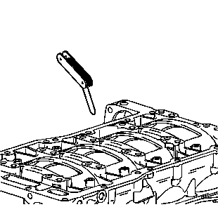
- Measure the connecting rod side clearance with a feeler gauge.
The correct clearance is 0.070-0.370 mm
(0.0027-0.0145 in).


