For 1990-2009 cars only
Removal Procedure
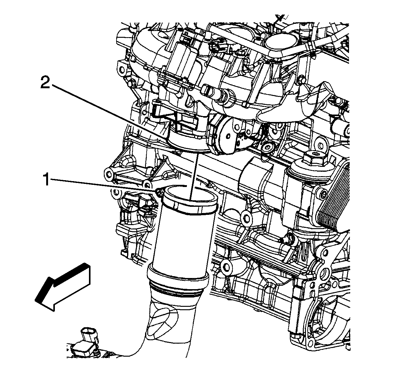
- Loosen the charge air cooler outlet pipe clamp (1) at the intake manifold (2).
- Disconnect the engine wiring harness electrical connector from the intake air pressure and temperature sensor.
- Reposition the hose clamp and remove the vacuum hose from the outlet pipe.
- Remove the right engine splash shield. Refer to Engine Splash Shield Replacement - Right Side.
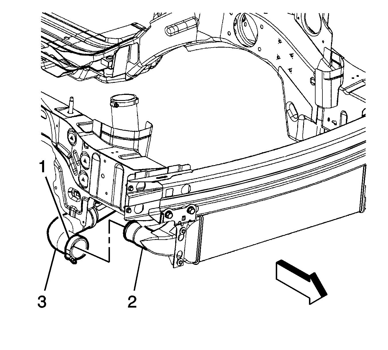
- Loosen the charge air cooler outlet pipe clamp (1) at the charge air cooler assembly (2).
- Remove the charge air cooler outlet pipe (3).


Installation Procedure
- Install the charge air cooler outlet pipe (3) to the charge air cooler assembly (2).
- Install the right engine splash shield. Refer to Engine Splash Shield Replacement - Right Side.
- Connect the engine wiring harness electrical connector to the intake air pressure and temperature sensor.
- Install the vacuum hose and reposition the hose clamp.
- Install the charge air cooler outlet pipe to the intake manifold (2) and tighten the charge air cooler outlet pipe clamp (1).
Notice: Refer to Fastener Notice in the Preface section.

Tighten
Tighten the clamp to 5 N·m (44 lb in).

Tighten
Tighten the clamp to 5 N·m (44 lb in).
