Water Pump Replacement L61/LE5
Special Tools
J 43651 Water Pump Holding Tool
Removal Procedure
- Remove the thermostat housing. Refer to Engine Coolant Thermostat Housing Replacement .
- Remove the water pump access plate from the front cover.
- Remove the right hand fender liner. Refer to Front Fender Liner Replacement .
- Drain the coolant from the water pump using the plug at the bottom of the pump.
- Install the J 43651 into position.
- Tighten the bolts on the water pump holding tool into the threads on the water pump sprocket.
- Install the access cover bolts that were removed earlier to secure the water pump holding tool to the front cover assembly.
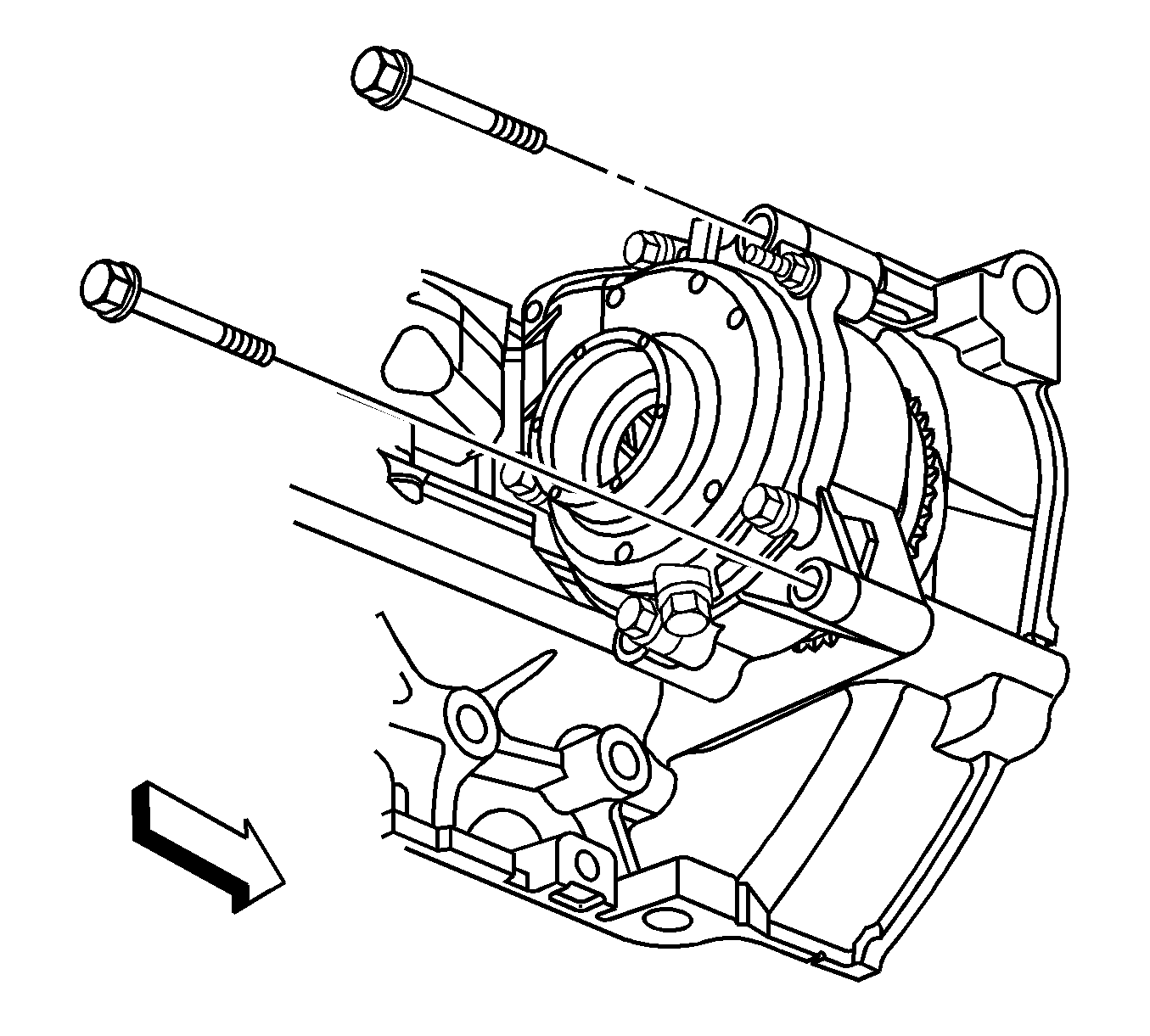
- Remove the 3 inner water pump sprocket to water pump blots.
- Remove the 2 water pump bolts.
- Remove the rear 2 water pump bolts.
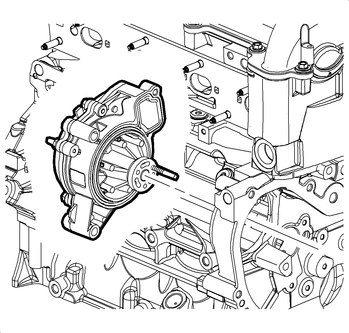
- Remove the water pump.
- Remove and discard the water pump O-ring seal.
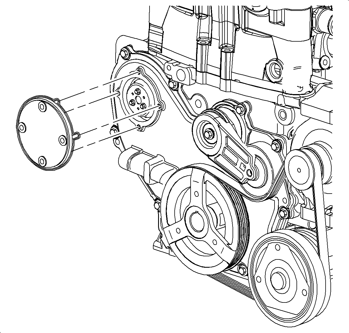
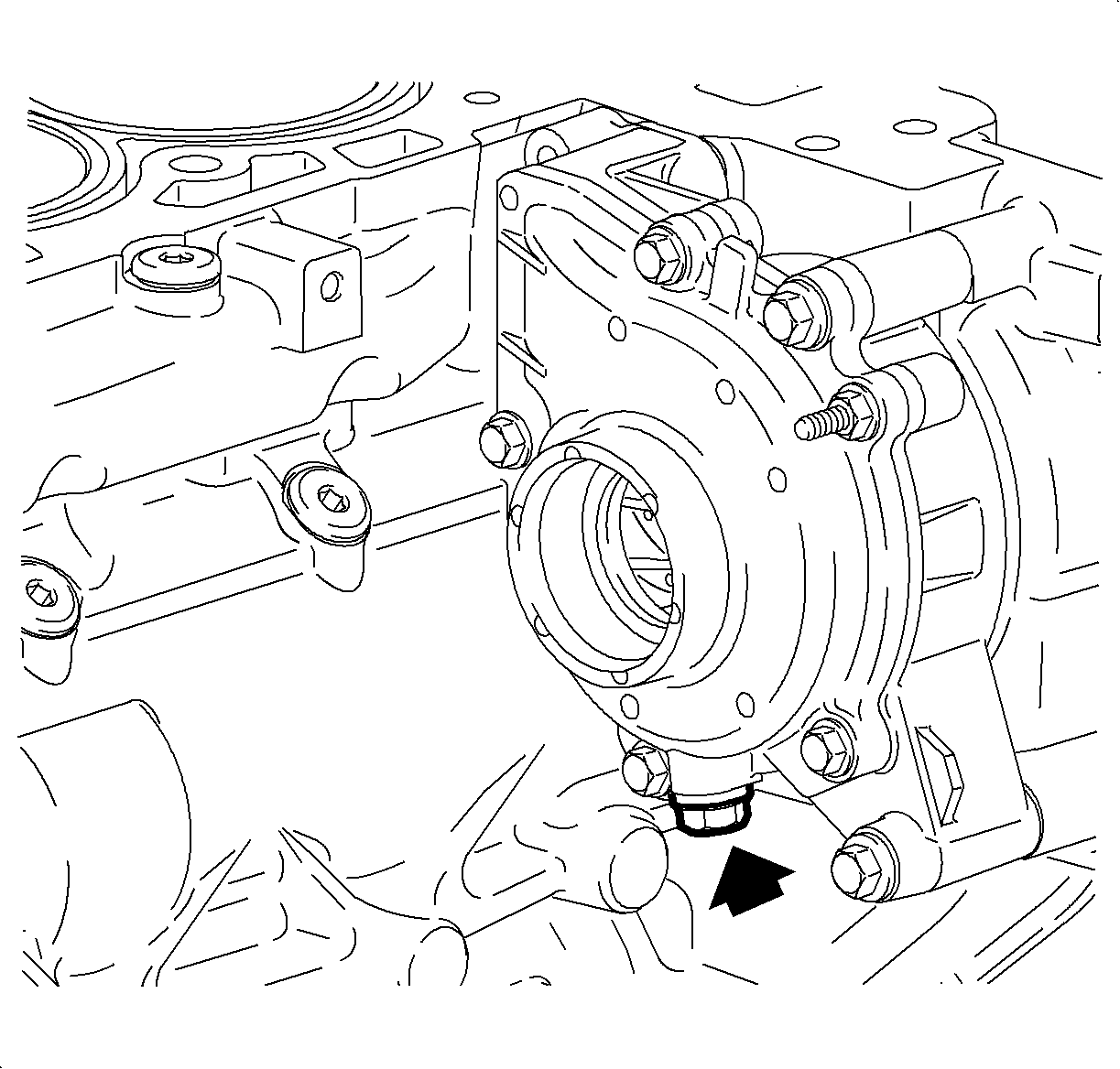
Important: A drain plug has been provided at the bottom of the water pump assembly for additional coolant drainage from the engine block and water pump.
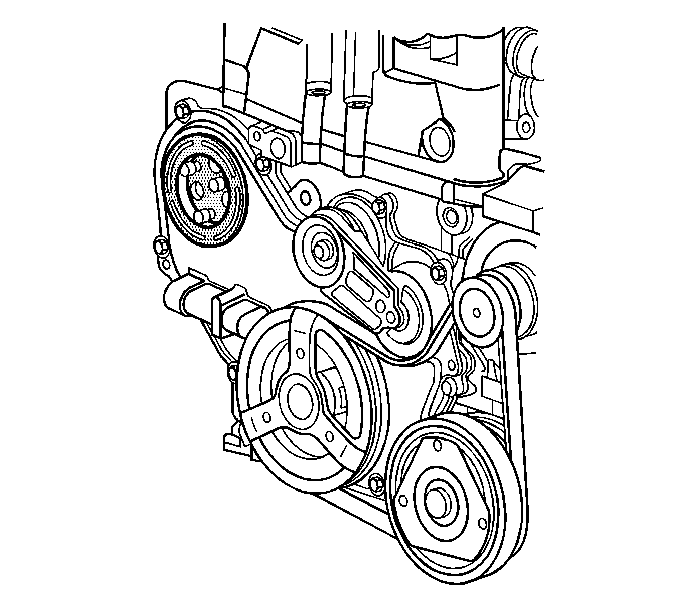
Important: The water pump holding tool supports the sprocket and chain during water pump service. The tool must be used or the balance shaft must be re-timed.
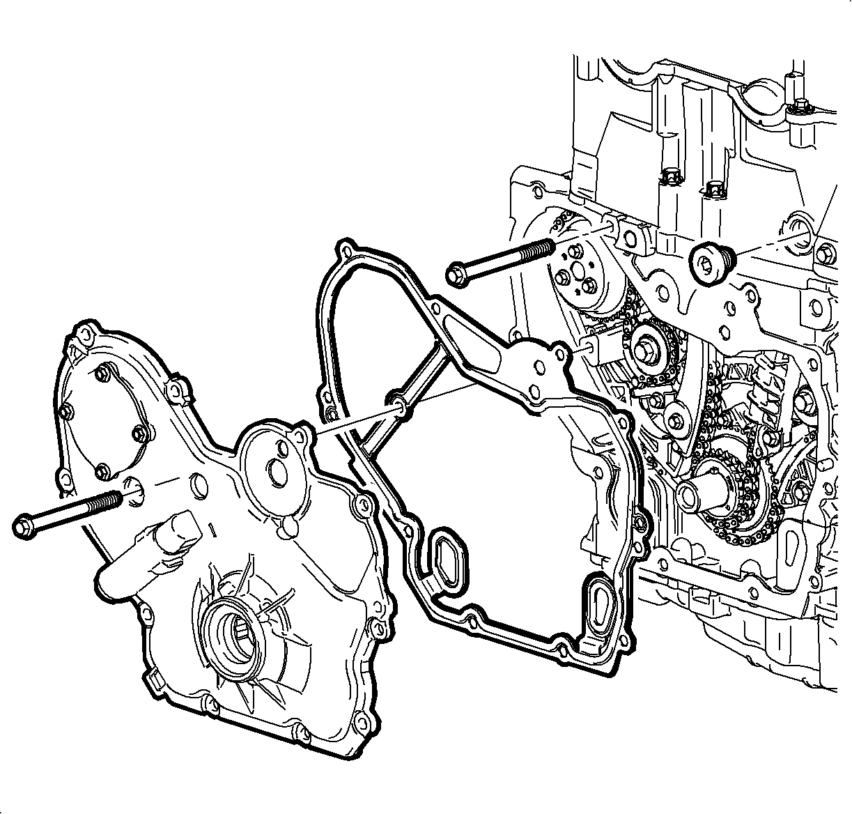
Important: Be sure to remove both water pump bolts from the front of the engine block.
Installation Procedure
- Install a NEW water pump O-ring seal.
- Using the guide pin, align the pin with the water pump holding tool.
- Position the water pump against the engine block and hand tighten the water pump bolts.
- Install the inner water pump sprocket bolts. After 2 are snug, remove the guide pin and install the 3rd bolt.
- Tighten the water pump sprocket bolts last.
- Remove the J 43651 .
- Install the water pump access plate and bolts.
- Install the right hand fender liner. Refer to Front Fender Liner Replacement .
- Install the thermostat housing. Refer to Engine Coolant Thermostat Housing Replacement .
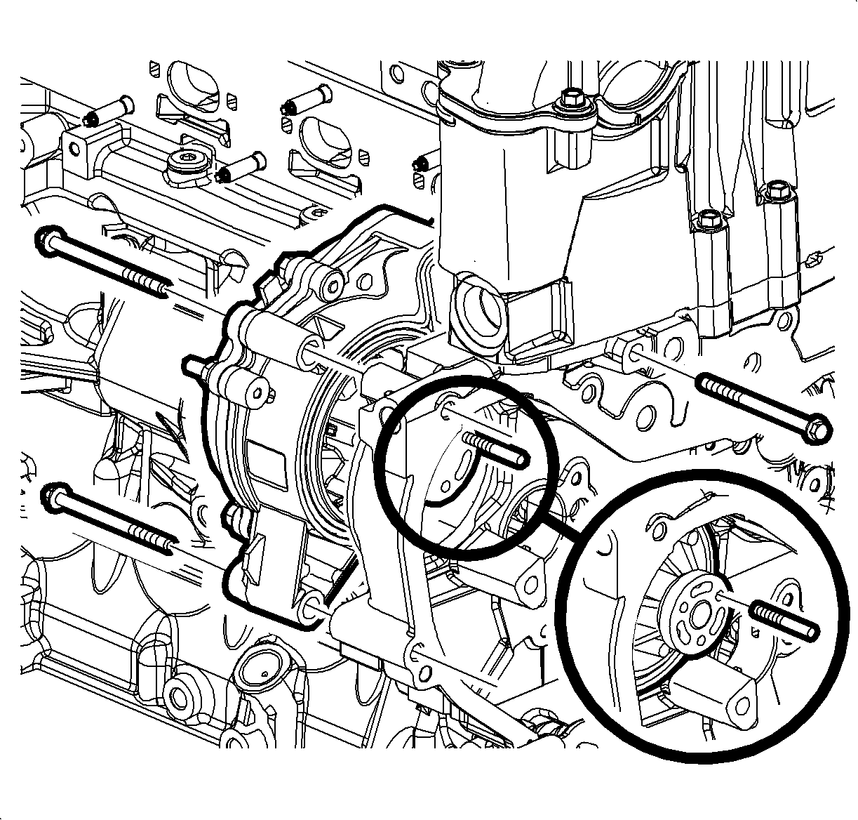
Important: Prior to installing the water pump, read the entire procedure. This will help avoid balance shaft chain re-timing and ensure proper sealing.
Important: A guide pin can be created to aid in water pump alignment. Use a M6 m x 6 mm stud. Thread the pin into the water pump sprocket.
Notice: Refer to Fastener Notice in the Preface section.
Tighten
Tighten the water pump bolts to 25 N·m (18 lb ft).
Tighten
Tighten the water pump sprocket bolts to 10 N·m (89 lb in).


Tighten
Tighten the bolts to 10 N·m (89 lb in).
Water Pump Replacement LNF
Special Tools
J 43651 Water Pump Holding Tool
Removal Procedure
- Raise and Support the vehicle. Refer to Lifting and Jacking the Vehicle.
- Remove the right engine splash shield. refer to Engine Splash Shield Replacement - Right Side.
- Remove the bolts (1) retaining the water pump access plate (2) and remove the plate from the front cover (3). Discard the seal.
- Drain the coolant from the water pump using the plug at the bottom of the pump. Refer to Cooling System Draining and Filling.
- Remove the thermostat housing. Refer to Engine Coolant Thermostat Housing Replacement.
- Remove the radiator outlet pipe from the rear of the water pump and the thermostat housing by gently twisting.
- Install the J 43651 (1) into position.
- Tighten the bolts on the water pump holding tool (2) into the threads on the water pump sprocket.
- Install the access cover bolts that were removed earlier to secure the water pump holding tool to the front cover assembly.
- Remove the three inner water pump sprocket to water pump bolts.
- Remove the two front water pump bolts.
- Remove the two rear water pump bolts.
- Remove the water pump.
- Remove and discard the water pump O-ring seal.
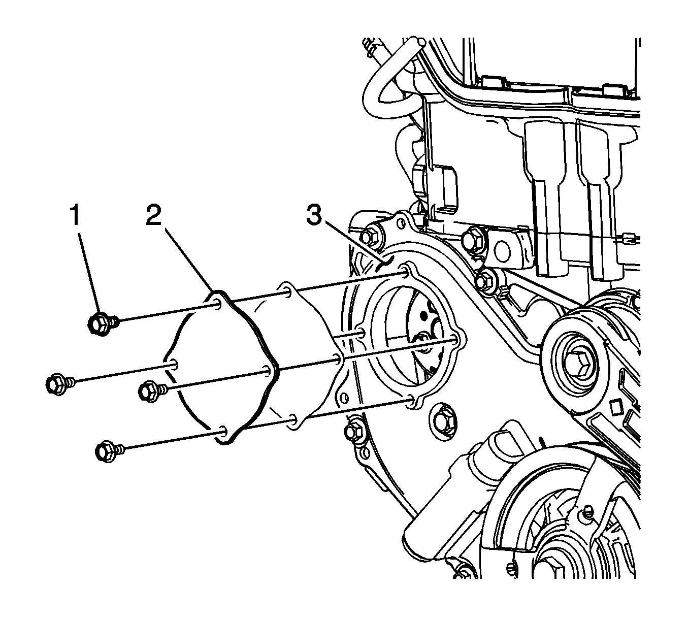
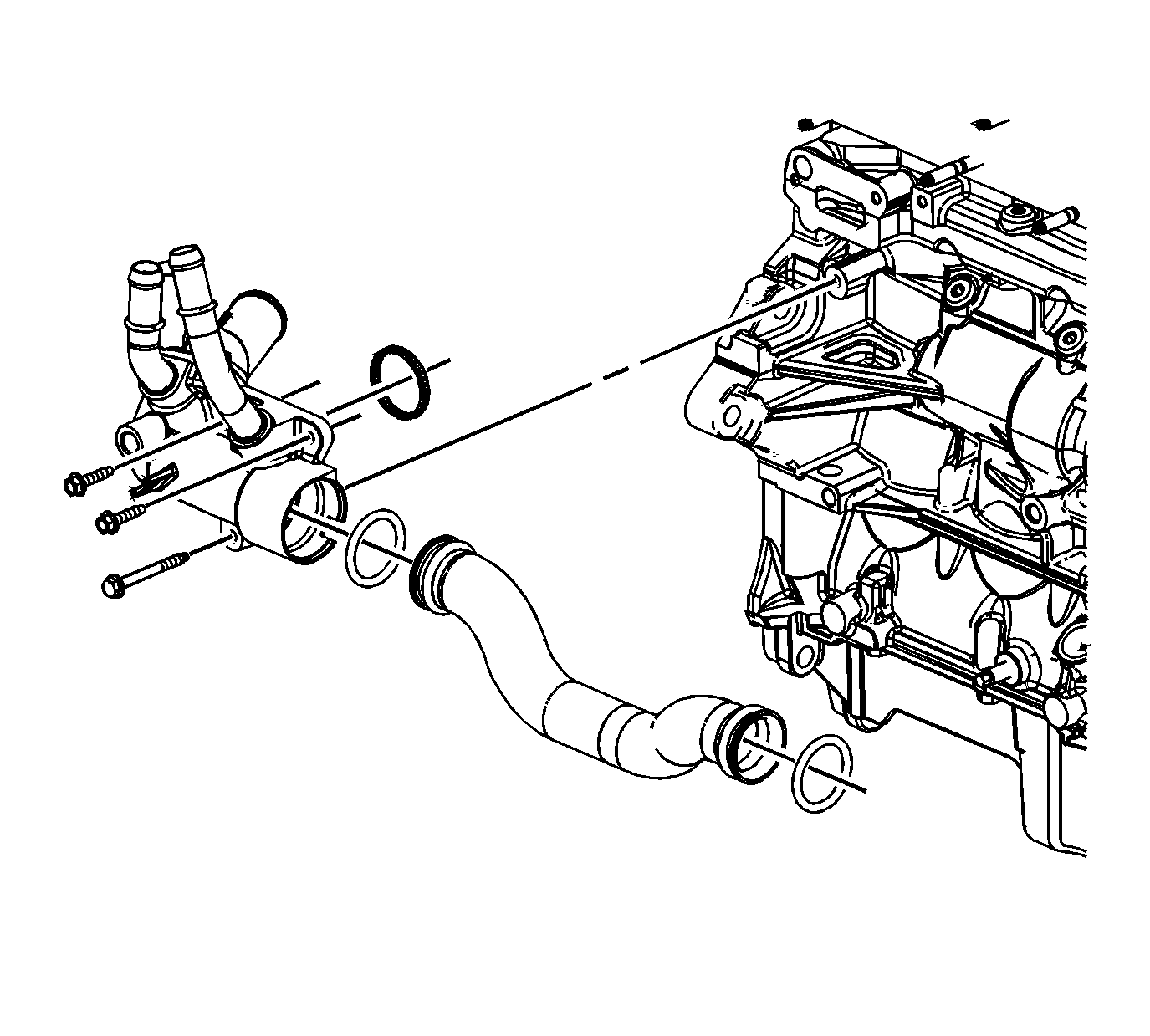
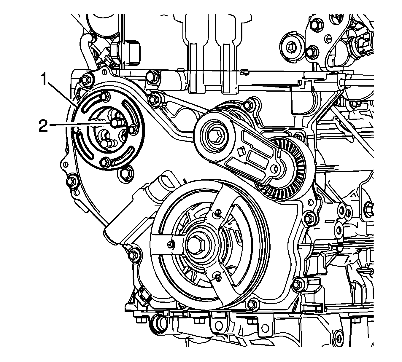
Important: The water pump holding tool supports the sprocket and chain during water pump service. The tool must be used or the balance shaft will have to be re-timed.

Important: Be sure to remove both front water pump bolts from the front of the engine block.


Installation Procedure
- Install a NEW water pump O-ring seal.
- Using the guide pin, align the pin with the water pump holding tool.
- Position the water pump against the engine block and hand tighten the front and rear water pump bolts.
- Install the inner water pump sprocket bolts. After two bolts are snug, remove the guide pin and install the 3rd bolt.
- Tighten the front and rear water pump bolts to 25 N·m (18 lb ft).
- Tighten the water pump sprocket bolts to 10 N·m (89 lb in).
- Remove the J 43651 (1).
- Install the water pump access plate and bolts, with a NEW seal.
- Install the radiator outlet pipe to the rear of the water pump and the thermostat housing using new O rings.
- Install the thermostat housing. Refer to Engine Coolant Thermostat Housing Replacement.
- Install the right engine splash shield. refer to Engine Splash Shield Replacement - Right Side.
- Lower the vehicle.
- Refill the coolant system to specifications and inspect for leaks. Refer to Cooling System Draining and Filling.

Important: Prior to installing the water pump, read the entire procedure. This will help avoid balance shaft chain re-timing and ensure proper sealing.
Important: A guide pin can be created to aid in water pump alignment. Use a M 6 m x 6 mm stud. Thread the pin into the water pump sprocket.
Notice: Refer to Fastener Notice in the Preface section.
Tighten


Tighten
Tighten the bolts to 10 N·m (89 lb in).

