Removal Procedure
- Remove the left front tire and wheel assembly. Refer to Tire and Wheel Removal and Installation.
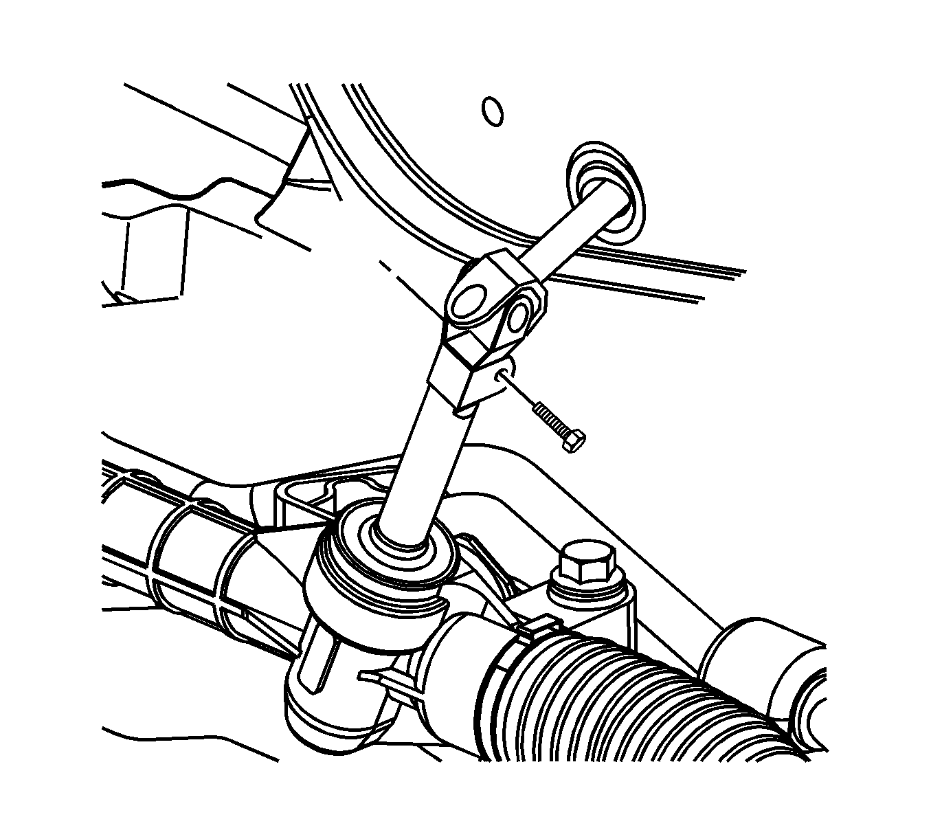
- Remove the intermediate steering shaft bolt at the steering gear.
- Disconnect the intermediate steering shaft from the steering gear.
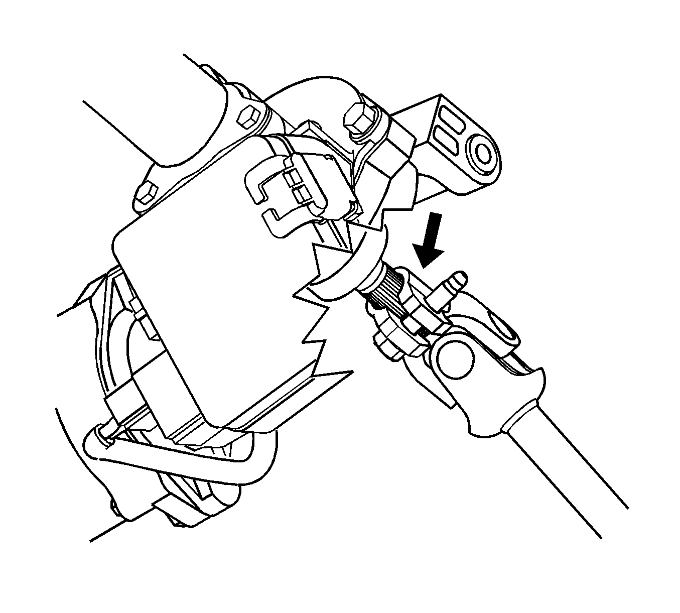
- Place scribe marks on the intermediate steering shaft and the steering column shaft prior to removal.
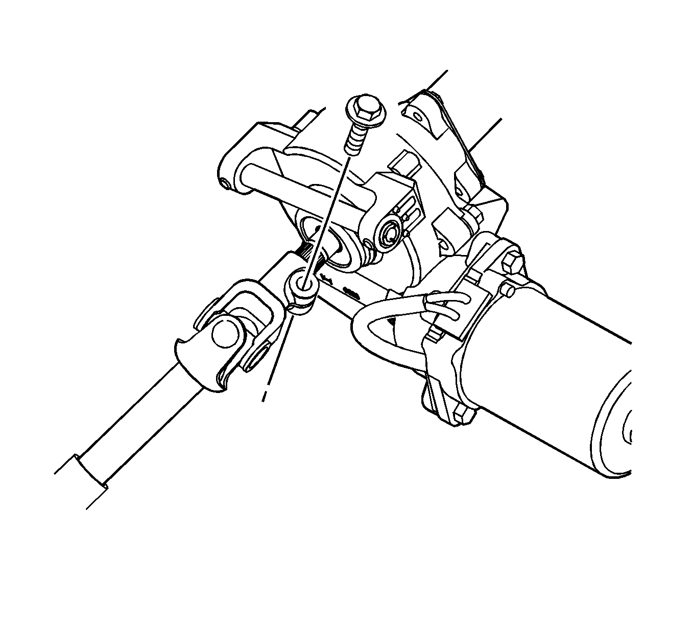
- Remove the intermediate steering shaft bolt at the steering column.
- Disconnect the intermediate steering shaft from the steering column shaft.
- Unseat the intermediate steering shaft seal from the body pass-through.
- Remove the intermediate steering shaft and seal assembly from the vehicle.
Notice: Secure the steering wheel utilizing a strap to prevent rotation. Locking of the steering column will prevent damage and a possible malfunction of the SIR system. The steering wheel must be secured
in position before disconnecting the following components:
• The steering column • The intermediate shaft • The steering gear


Important: Scribe marks will be needed for proper alignment of the intermediate steering shaft.

Installation Procedure
- Perform the following procedure before installing the lower and upper intermediate steering shaft bolts:
- If installing a new intermediate steering shaft then transfer the scribed marks made previously.
- Position the intermediate steering shaft and seal assembly to the vehicle.
- Seat the intermediate steering shaft seal to the body pass-through.
- Align the scribed marks on the intermediate steering shaft to the scribed marks on the steering column shaft.
- Connect the intermediate steering shaft to the steering column.
- Install a new intermediate steering shaft bolt.
- Connect the intermediate steering shaft to the steering gear.
- Install a new intermediate steering shaft bolt.
- Install the left front tire and wheel assembly. Refer to Tire and Wheel Removal and Installation.
- If equipped with RPO JL4, calibrate the steering angle sensor. Refer to Control Module References.
| 1.1. | Remove all traces of the original adhesive patch. |
| 1.2. | Clean the threads of the bolt with denatured alcohol, or equivalent, and allow to dry. |
| 1.3. | Apply threadlocker GM P/N 12345493 (Canadian P/N 10953488) or blue, medium LOCTITE™ 242. |
Important: Failure to transfer the scribed marks may result in an off-center steering wheel.
Important: Inspect the intermediate steering shaft seal from the engine compartment to make sure it is seated properly.
Notice: Refer to Fastener Notice in the Preface section.

Tighten
Tighten the bolt to 34 N·m (25 lb ft).

Tighten
Tighten the bolt to 34 N·m (25 lb ft).
