For 1990-2009 cars only
Removal Procedure
- Remove the camshaft position intake actuator. Refer to Camshaft Position Intake Actuator Replacement .
- Remove the high pressure fuel pump. Refer to High Pressure Fuel Pump Replacement .
- Mark the camshaft bearing caps to ensure they are installed in the same position.
- Remove the camshaft bearing cap bolts and caps.
- Remove the valve lifter follower.
- Remove the cylinder head opening plate bolts and plate.
- Remove the rear bearing cap bolts and cap.
- Remove the intake camshaft.
- Remove the valve rocker arms.
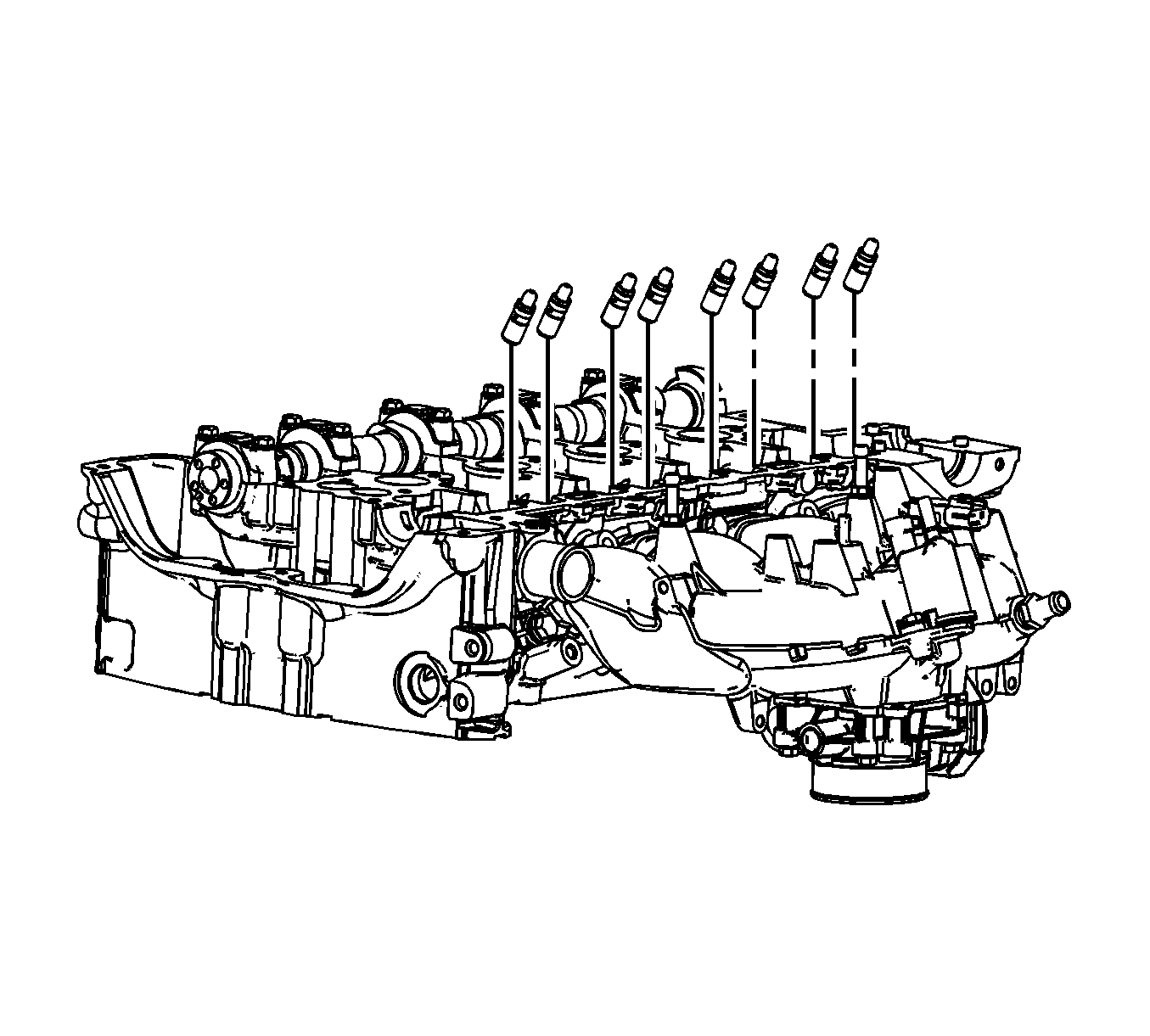
- Remove the hydraulic valve lash adjusters.
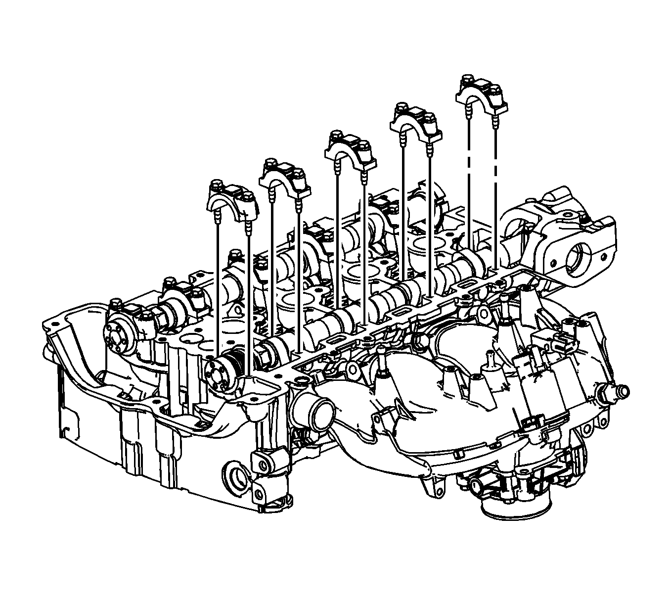
Important: Remove each bolt on each cap one turn at a time until there is no spring tension pushing on the camshaft.
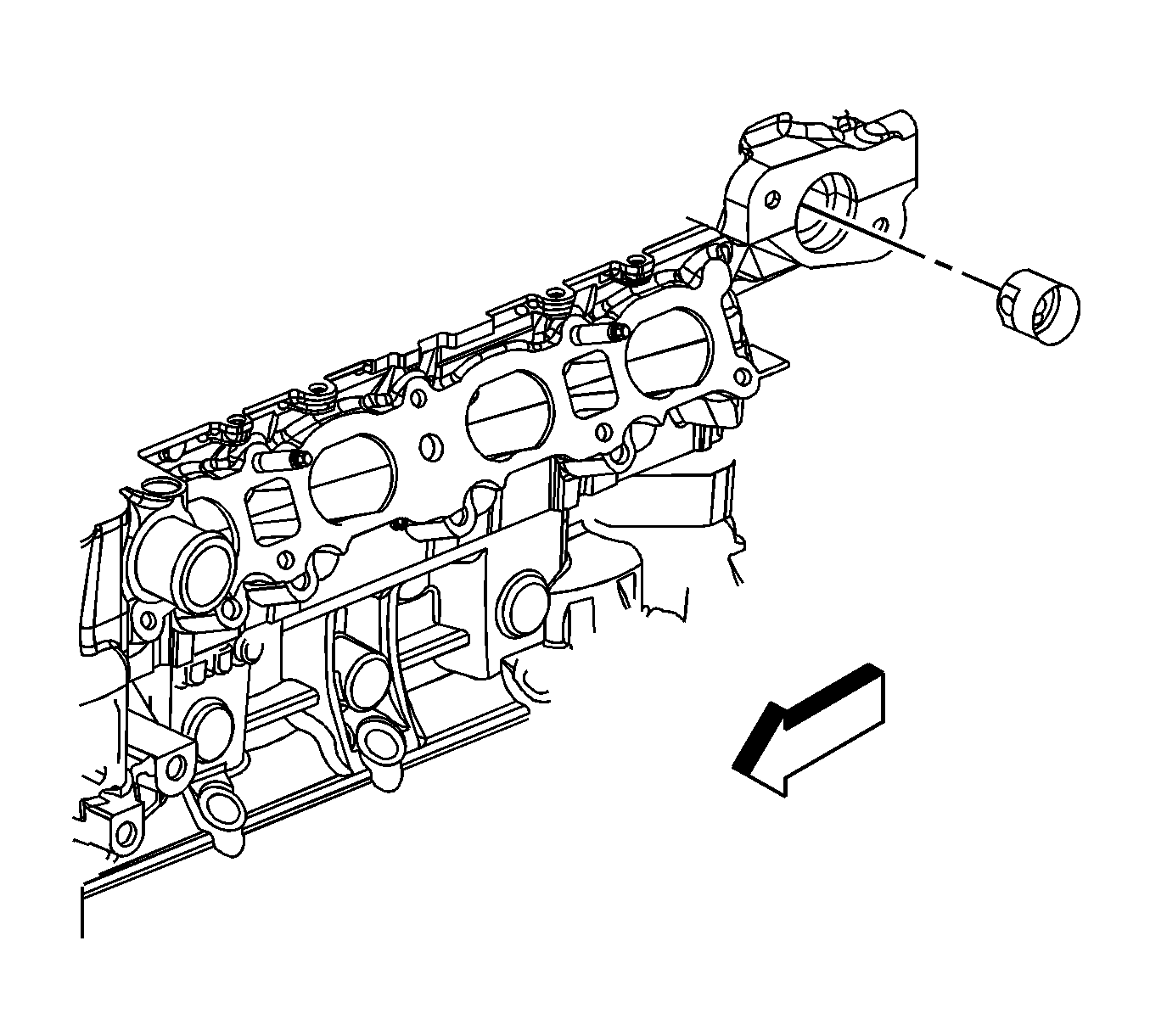
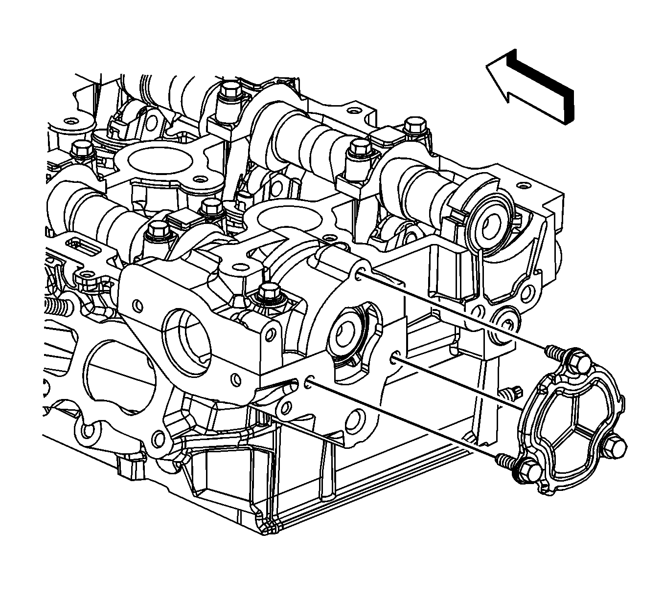
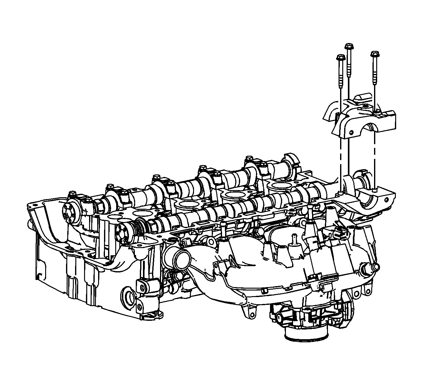
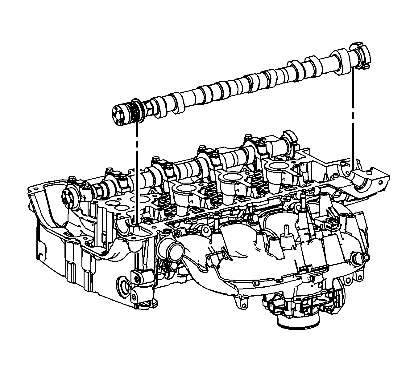
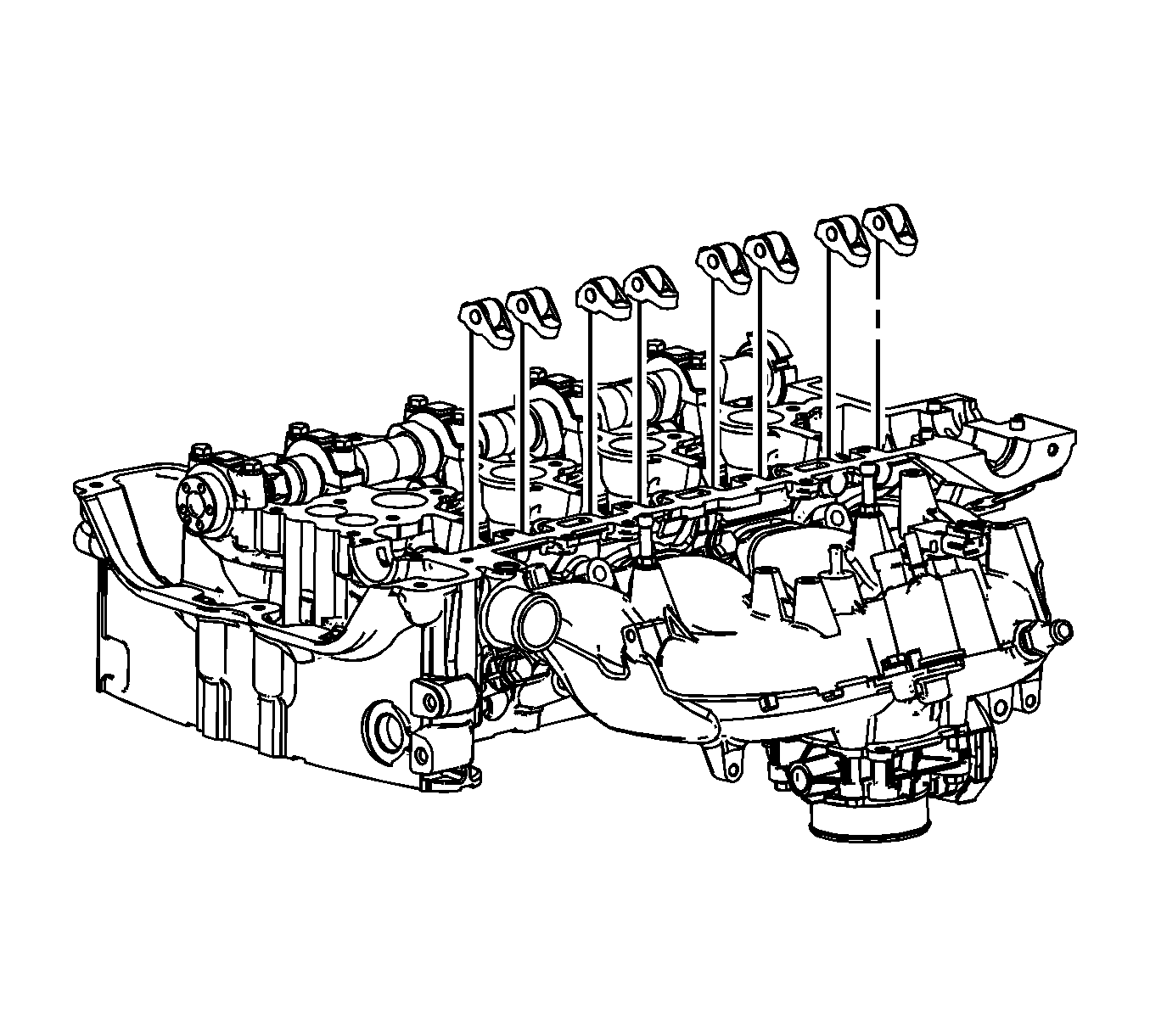
Important: Keep all of the roller followers and hydraulic valve lash adjusters in order so that they can be reinstalled in their respective locations.
Installation Procedure
- Install the hydraulic valve lash adjusters into their bores in the cylinder head.
- Lubricate the hydraulic lash adjusters. Refer to Adhesives, Fluids, Lubricants, and Sealers .
- Lubricate the valve tips. Refer to Adhesives, Fluids, Lubricants, and Sealers .
- Position the valve rocker arms on the tip of the valve stem and on the valve lash adjuster. Lubricate the rocker arms. Refer to Adhesives, Fluids, Lubricants, and Sealers .
- Install the intake camshaft. Lubricate the camshaft. Refer to Adhesives, Fluids, Lubricants, and Sealers .
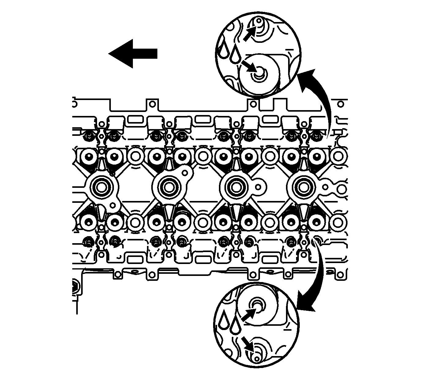
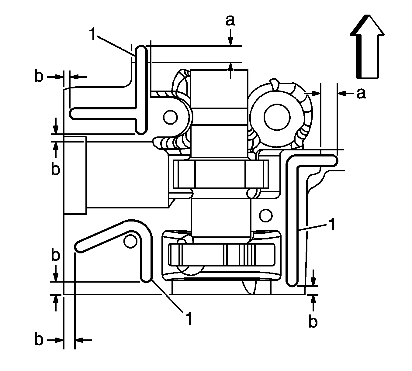
- Apply a 3.5 mm (0.138 in) bead of sealer (1) to the cylinder head. Refer to Adhesives, Fluids, Lubricants, and Sealers .
- In areas were the rear bearing cap ends on the perimeter rail, extend the bead of sealer 4.0 mm (0.1575 in) beyond the edge of the cap (a).
- Run the bead of sealer to within 4.0 mm (0.1575 in) of end points (b).
- Install the rear bearing cap and bolts.
- Install the cylinder head opening plate and bolts.
- Install the valve lifter follower.
- Position the camshaft bearing caps. Install the bearing cap bolts hand tight.
- Tighten the bearing cap bolts in increments of 3 turns until they are seated.
- Install the high pressure fuel pump. Refer to High Pressure Fuel Pump Replacement .
- Install the camshaft position intake actuator. Refer to Camshaft Position Intake Actuator Replacement .


Important: Used valve rocker arms MUST be returned to their original position on the camshaft. If the camshaft is being replaced, the rocker arms MUST also be replaced.

Notice: Refer to Fastener Notice in the Preface section.

Tighten
Tighten the bolts to 10 N·m (89 lb in).

Tighten
Tighten the bolts to 10 N·m (89 lb in).


Important: The caps should be installed on the cylinder head in sequence as shown on top of the bearing caps.
Tighten
Tighten the bolts to 10 N·m (89 lb in).
