Special Tools
| • | EN-47909
Injector Bore and Sleeve Cleaning Kit |
| • | EN-48266
Injector Seal Installer and Sizer |
Removal Procedure
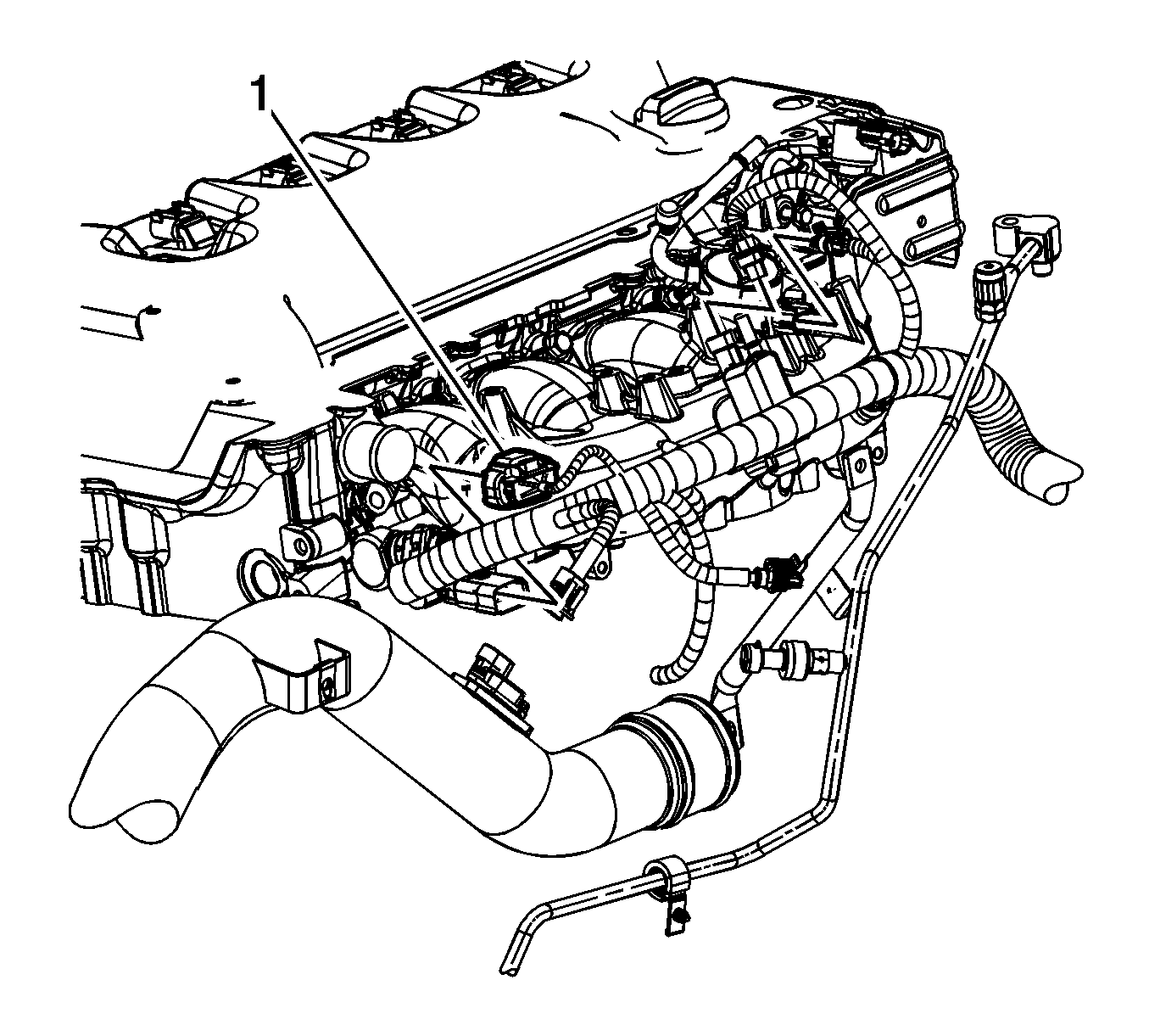
- Disconnect the engine wiring harness electrical connector (1) from the fuel injector wiring harness electrical connector.
- Remove the intake manifold assembly. Refer to
Intake Manifold Replacement
.
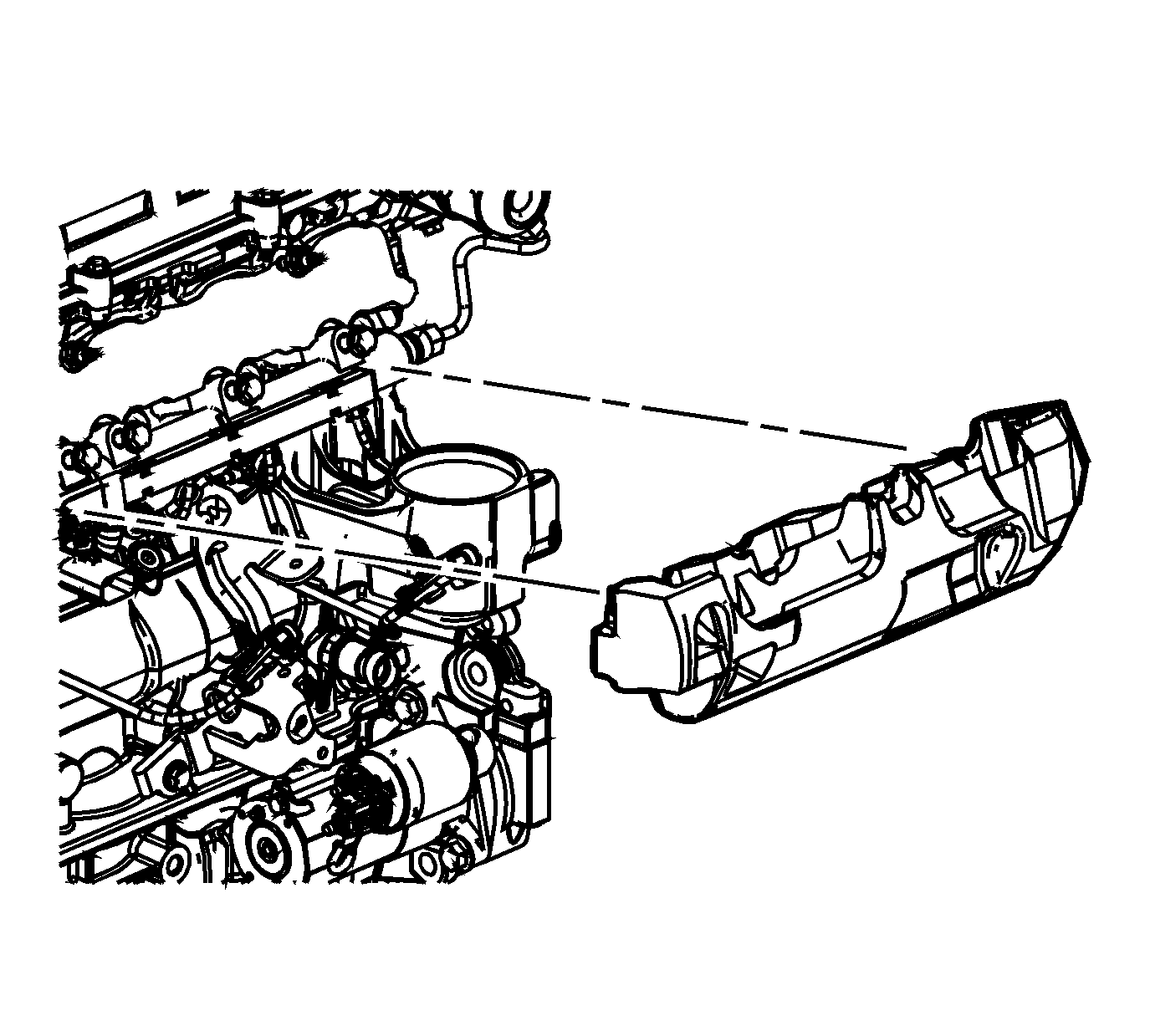
- Remove the fuel injector insulator.
- Relieve the high side fuel system pressure. Refer to
Fuel Pressure Relief
.
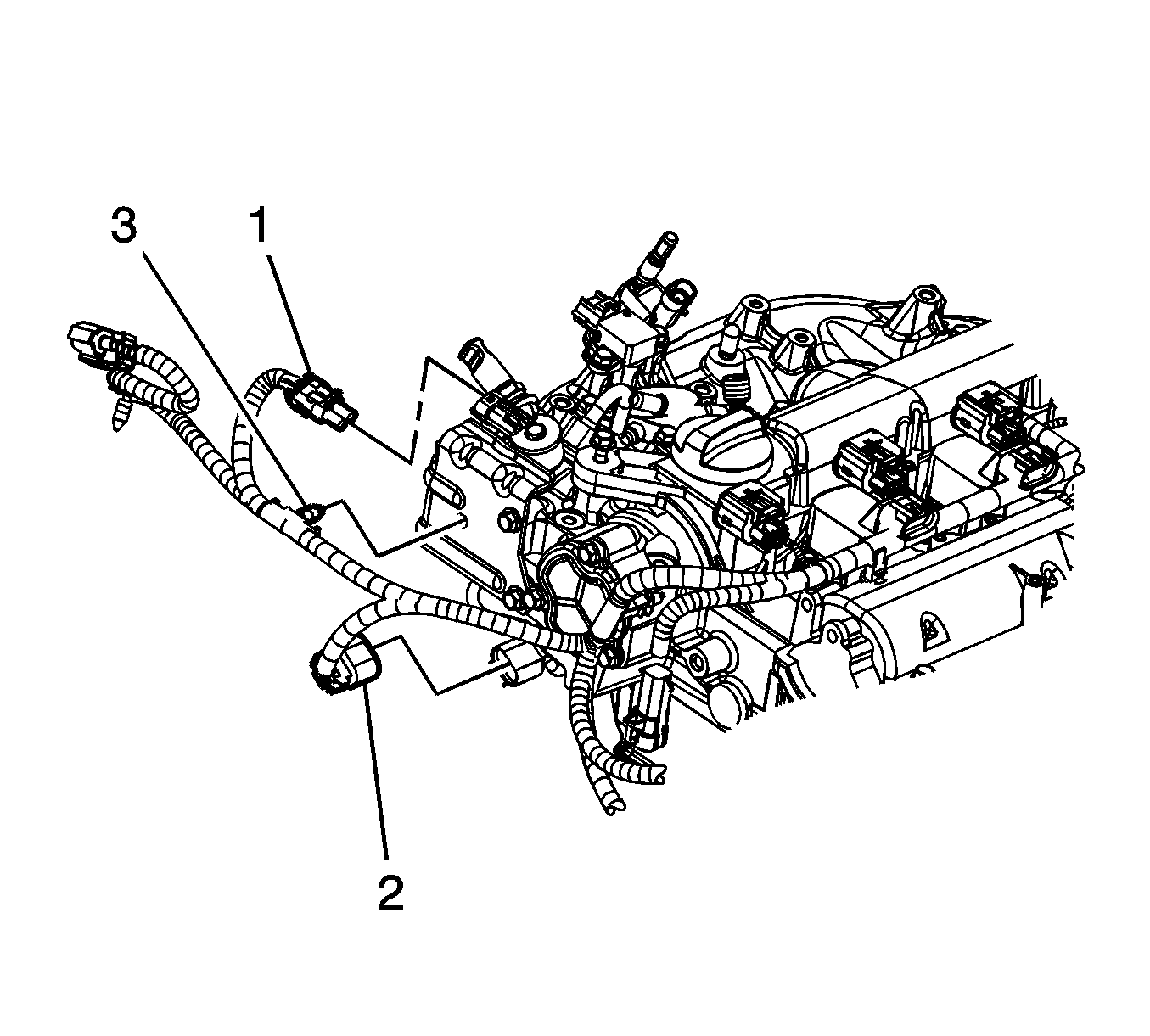
- Disconnect the engine wiring harness electrical connector (1) from the high pressure fuel pump.
- Remove the engine wiring harness clip (3) from the high pressure fuel pump cover.
- Remove the fuel feed intermediate pipe. Refer to
Fuel Feed Intermediate Pipe Replacement
.
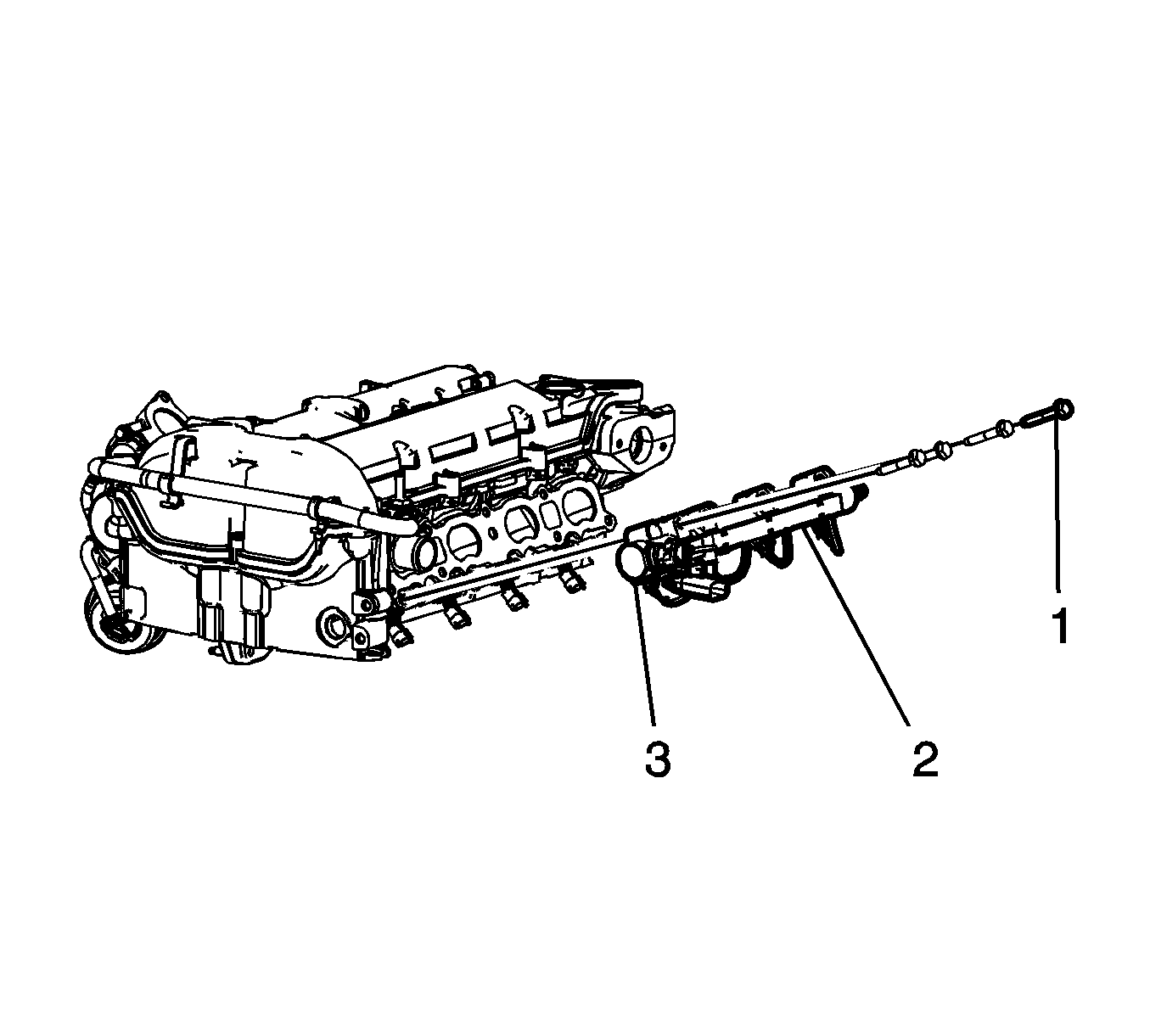
- Disconnect the fuel injector wiring harness electrical connectors from the fuel injectors.
- Remove the fuel rail bolts (1).
Important: Carefully remove the fuel rail. The fuel injectors may come out of the cylinder head with the fuel rail.
- Carefully remove the fuel rail (2).
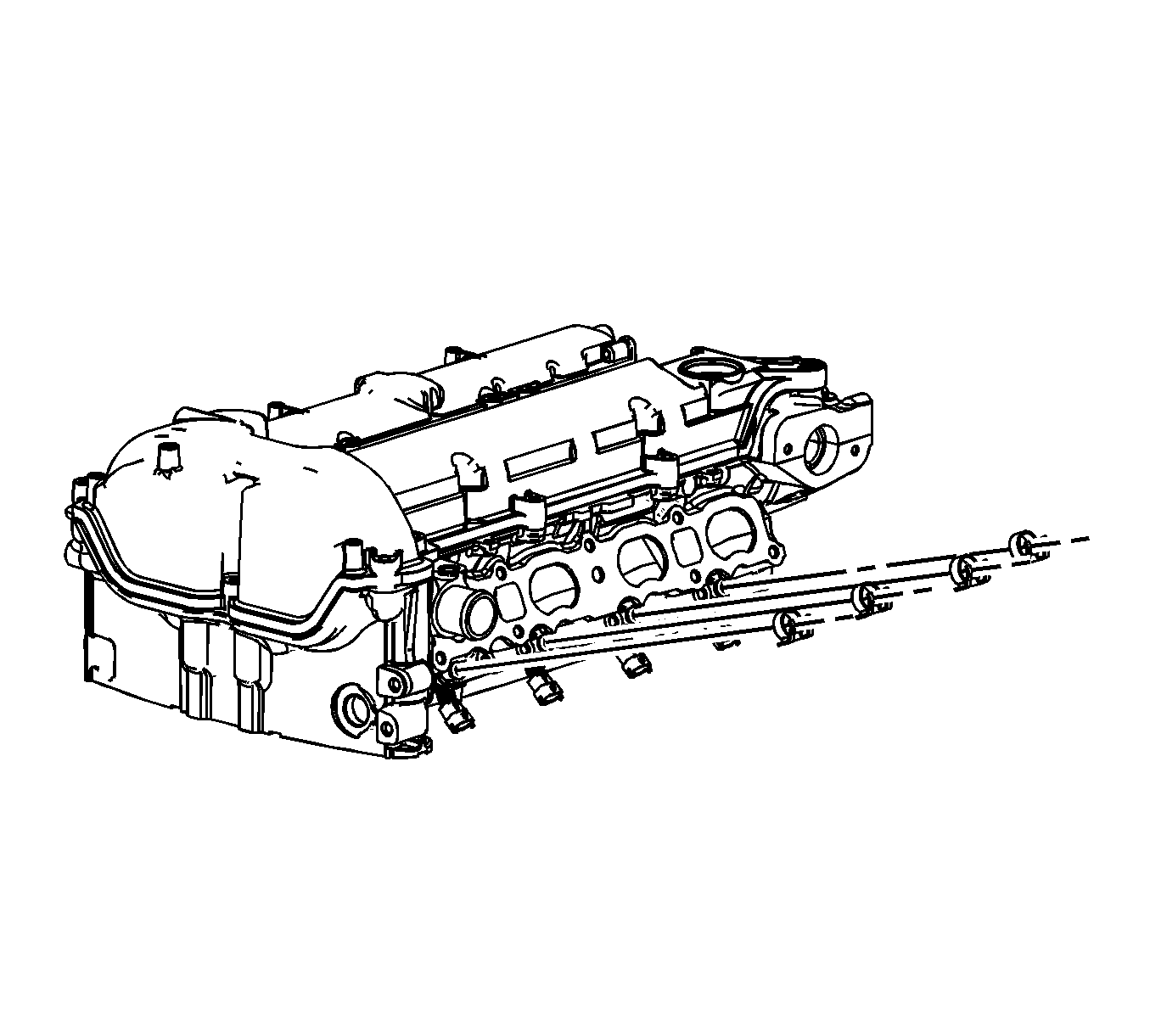
- Remove and discard the direct fuel injector hold down clamps.
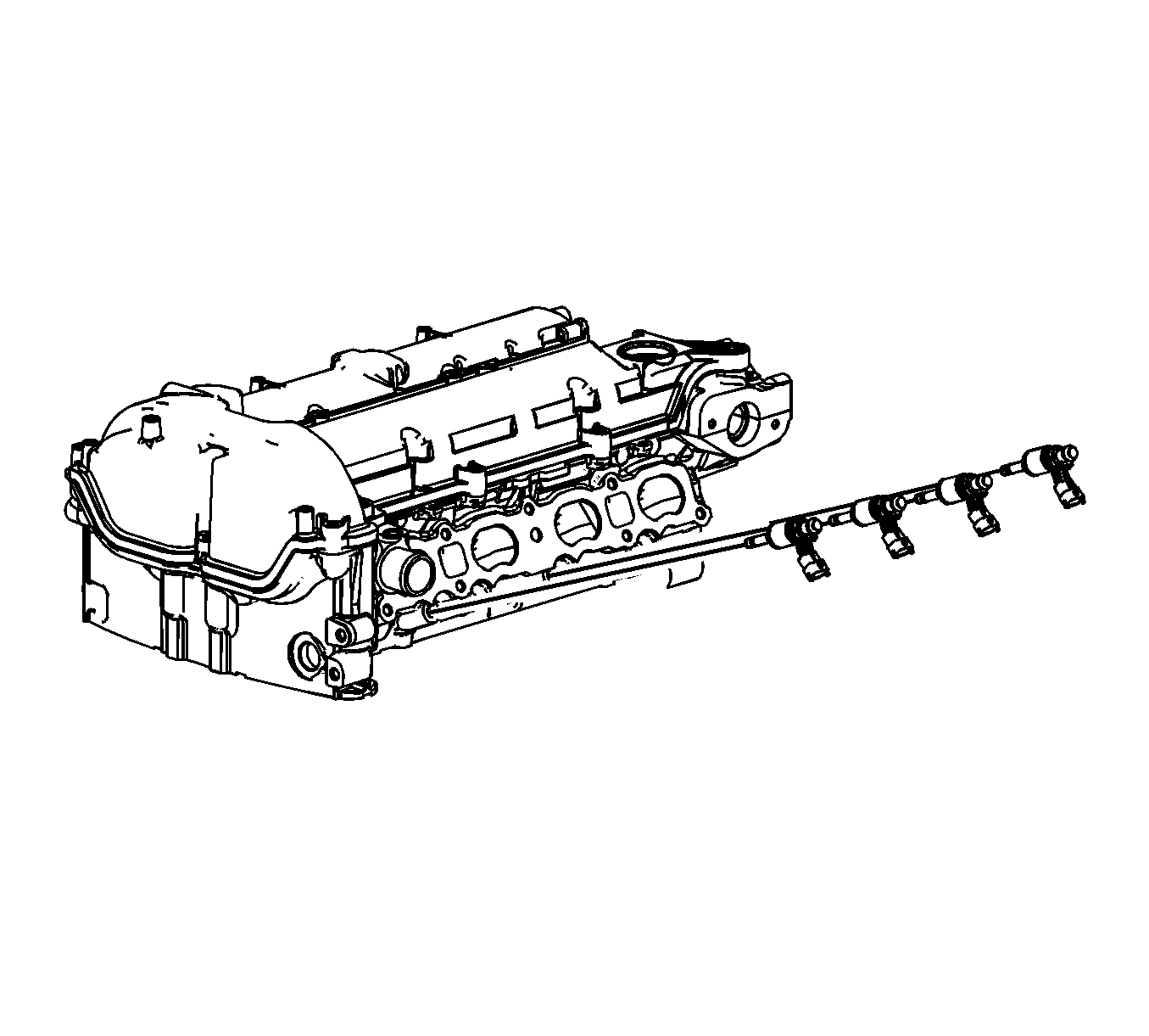
- Remove the direct fuel injectors.
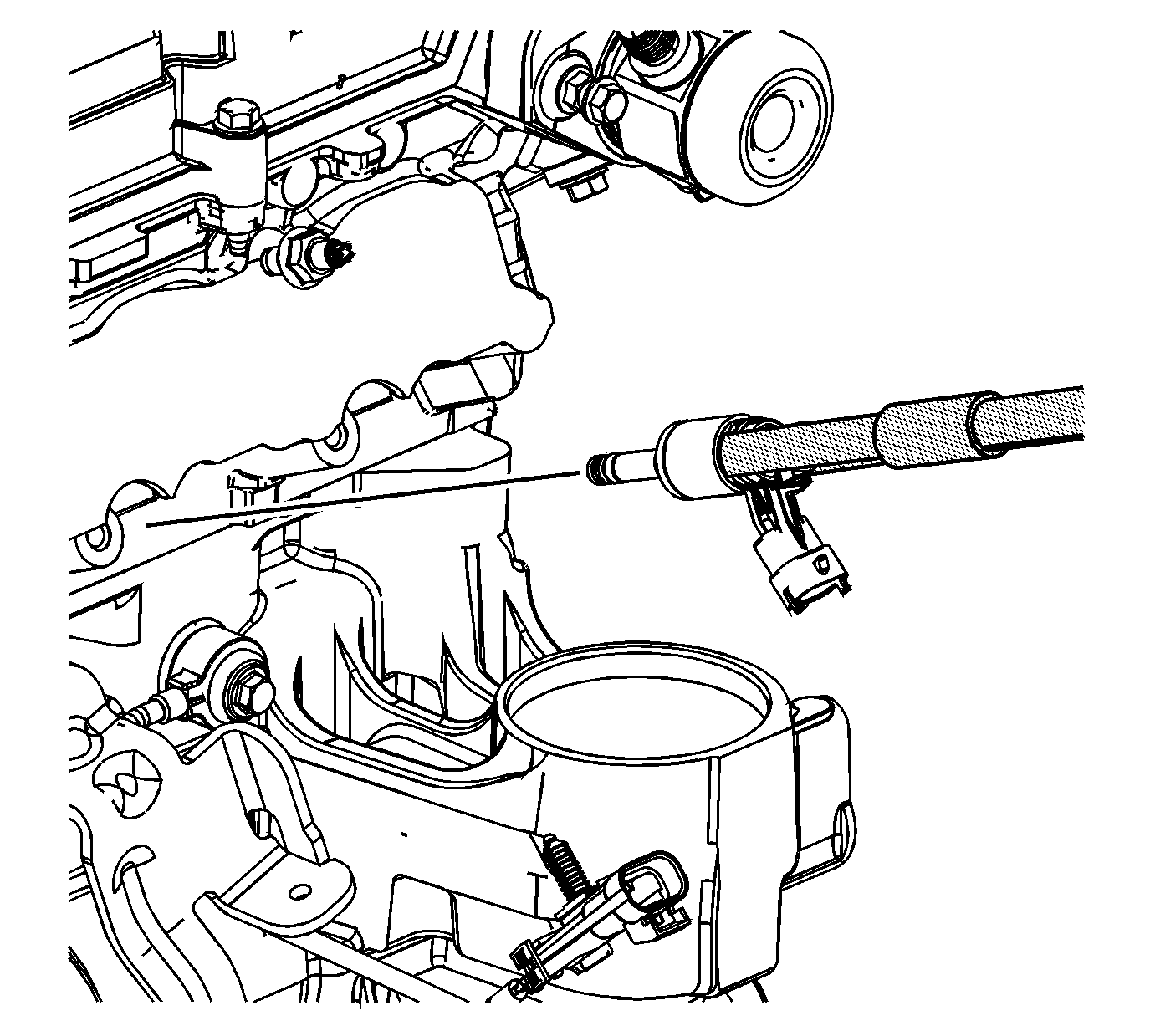
- If necessary, use the
J 2619-01
and the
J-37281-A
in order to remove the direct fuel injector(s).
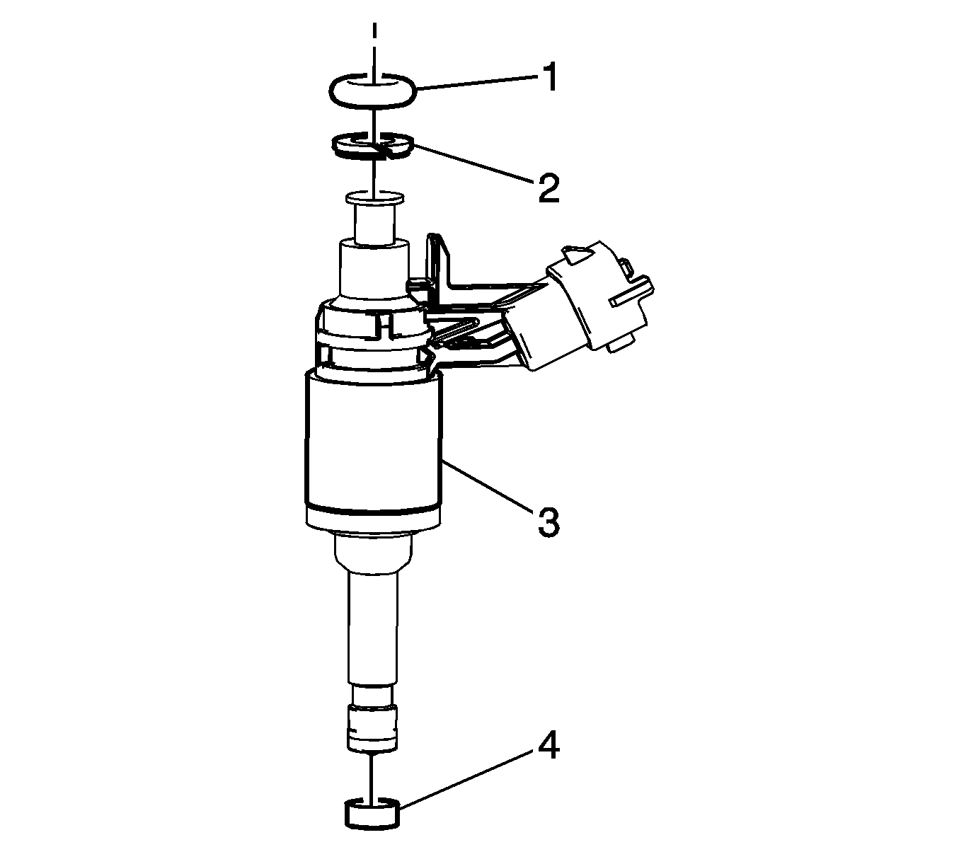
- Remove and discard the upper O-ring seal (1) and plastic spacer (2) from the injector(s).
- Carefully remove and discard the lower nylon seal (4) from the injector(s).
Installation Procedure

- Install a NEW plastic spacer (2) onto the fuel injector(s).
- Lubricate a NEW O-ring seal (1) with silicon free engine oil GM P/N 12345610 (Canadian P/N 993193) or equivalent.
- Install the NEW O-ring seal (1) onto the fuel injector(s).
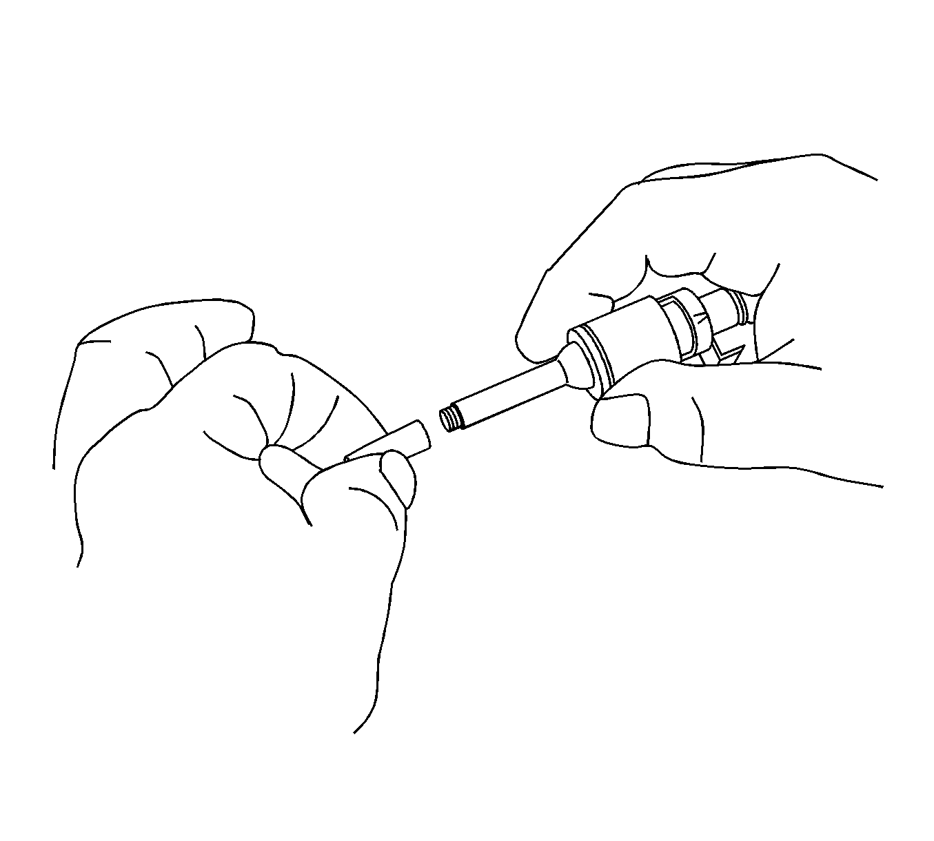
- From the
EN-48266
, position the EN 48266-1
to the injector tip.
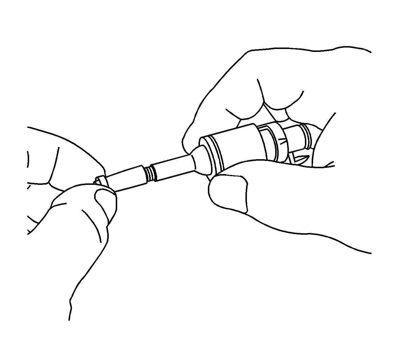
Important: DO NOT lubricate the NEW seal.
- Install a NEW seal onto the EN 48266-1.
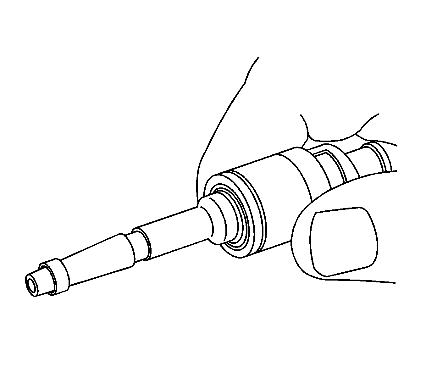
- Pull the NEW seal by hand over the EN 48266-1 and into the groove in the injector.
- Remove the EN 48266-1 from the injector tip.
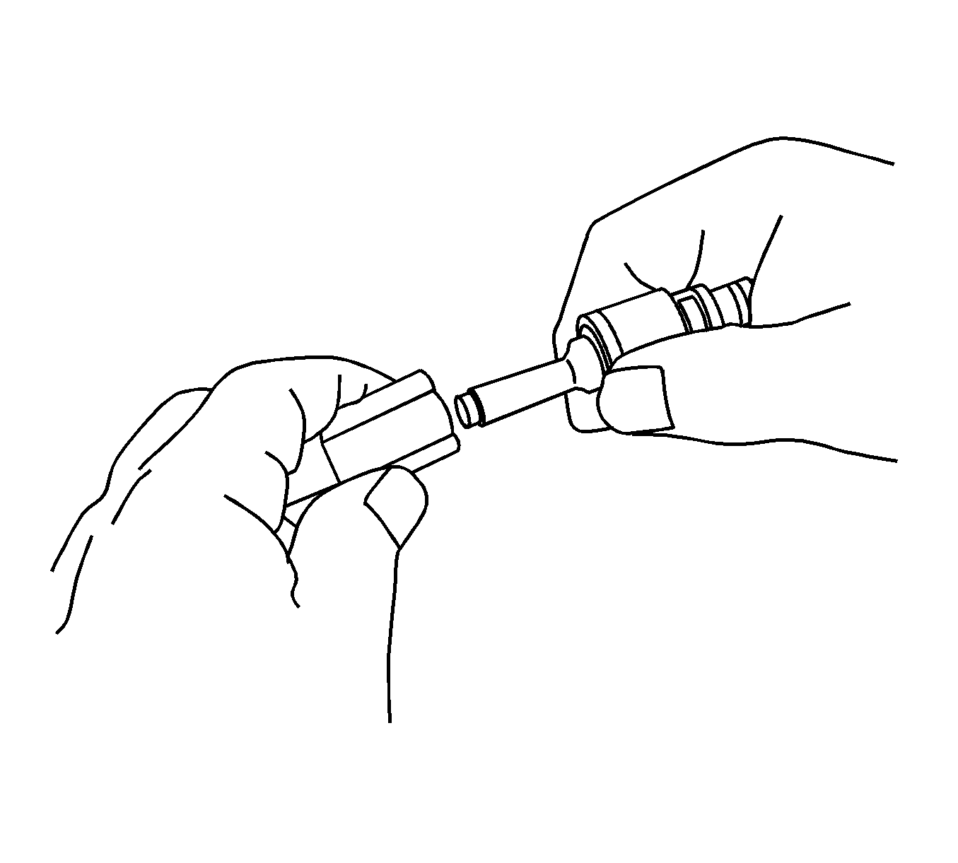
- From the
EN-48266
, install the EN 48266-2
to the injector tip.
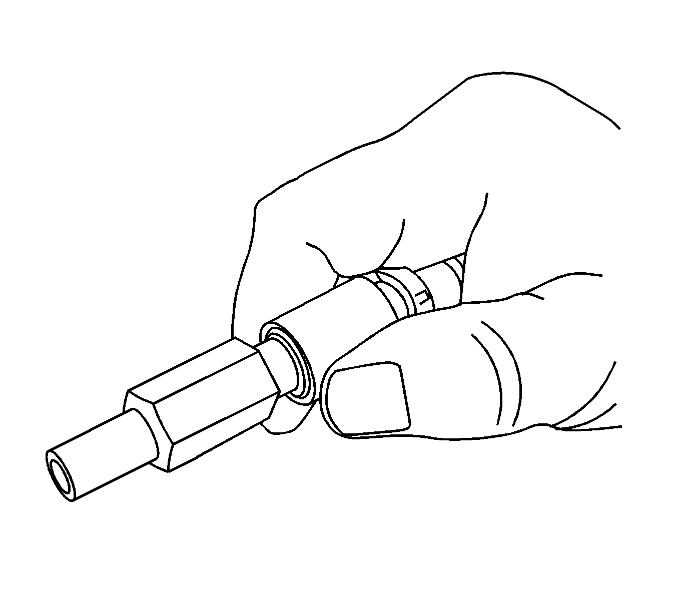
- Using the EN 48266-2, re-size the seal. Install the EN 48266-2, until it
bottoms out against the injector body, and rotate the EN 48266-2 while applying only moderate force 180 degrees in one direction and then 180 degrees back in the other direction.
- Remove the EN 48266-2.

- Install the direct fuel injectors to the cylinder head.

- Install the NEW direct fuel injector hold down clamps.

- Place the fuel rail (2) into position.
- Install the 2 outer fuel rail bolts (1) first, hand tight and install the remaining 2 bolts, hand tight.
- Connect the fuel injector wiring harness electrical connectors to the fuel injectors.
Notice: Refer to Fastener Notice in the Preface section.
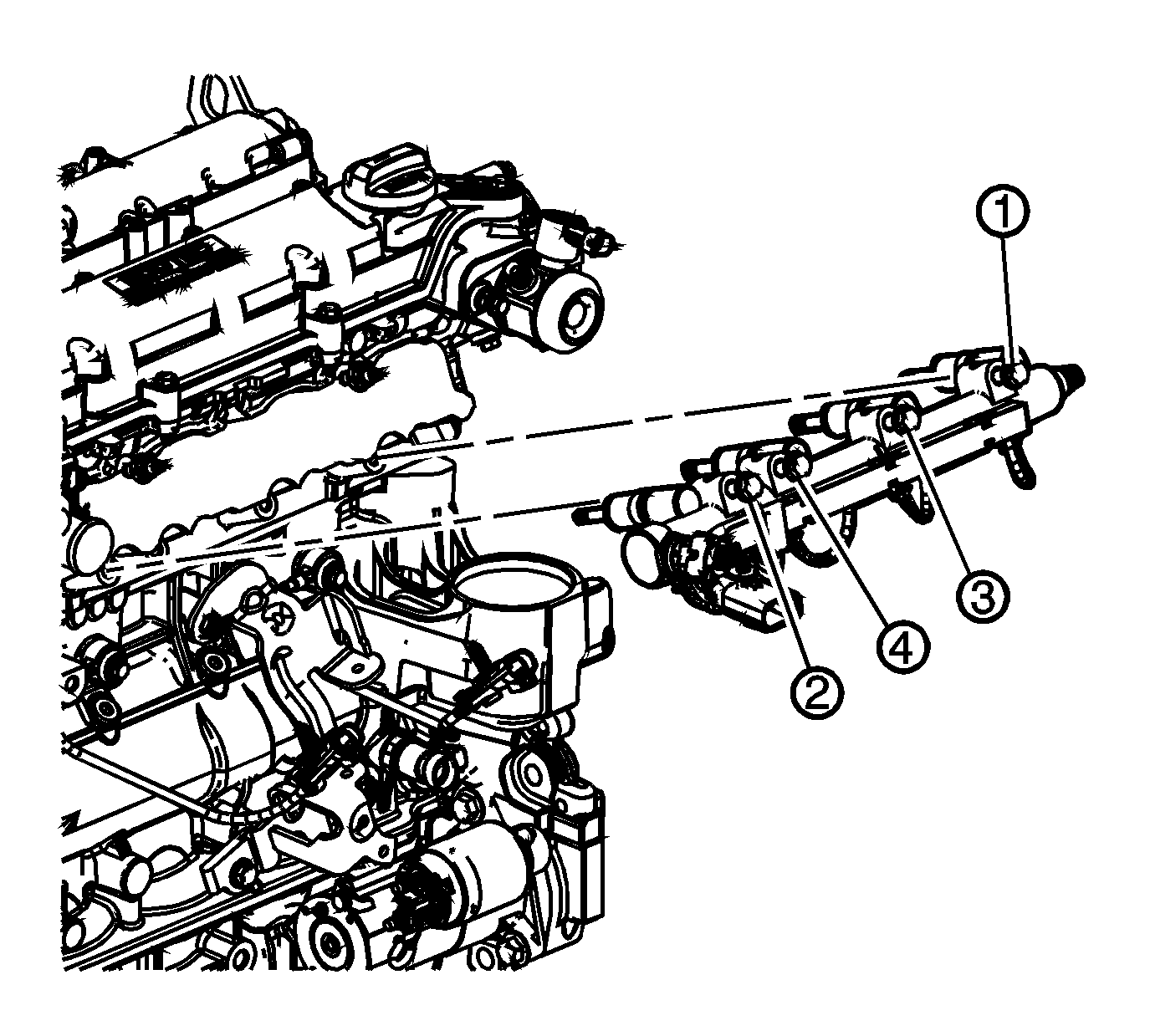
- Tighten the fuel rail bolts in the sequence shown.
Tighten
| • | Tighten the bolts a first pass to 22 N·m (16 lb ft). |
| • | Tighten the bolts a final pass to 22 N·m (16 lb ft). |
- Install the fuel feed intermediate pipe. Refer to
Fuel Feed Intermediate Pipe Replacement
.

- Connect the engine wiring harness electrical connector (1) to the high pressure fuel pump.
- Install the engine wiring harness clip (3) to the high pressure fuel pump cover.

- Install the fuel injector insulator.

- Connect the engine wiring harness electrical connector (1) to the fuel injector wiring harness electrical connector.
- Inspect for leaks using the following procedure:
| 22.1. | Turn ON the ignition, with the engine OFF for 2 seconds. |
| 22.2. | Turn OFF the ignition, for 10 seconds. |
| 22.3. | Turn ON the ignition, with the engine OFF. |
| 22.4. | Inspect for fuel leaks. |
- Install the low side fuel pressure service port cap.
- Tighten the fuel fill cap.
- Install the intake manifold assembly. Refer to
Intake Manifold Replacement
.


