Special Tools
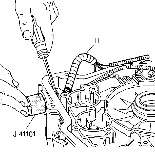
J 41101
Transaxle Connector Remover
Removal Procedure
- Remove the transmission side cover. Refer to
Control Valve Body Cover Replacement.
- Remove the control valve body. Refer to
Control Valve Body Replacement.

- Push the
J 41101
onto the pass-through connector from the outside of the transmission case in order to compress the pass-through
connector's retaining tabs.
- With the retaining tabs compressed, use a screwdriver in order to remove the pass-through connector through the inside of the transmission case.
- Remove the wiring harness (11).
Installation Procedure

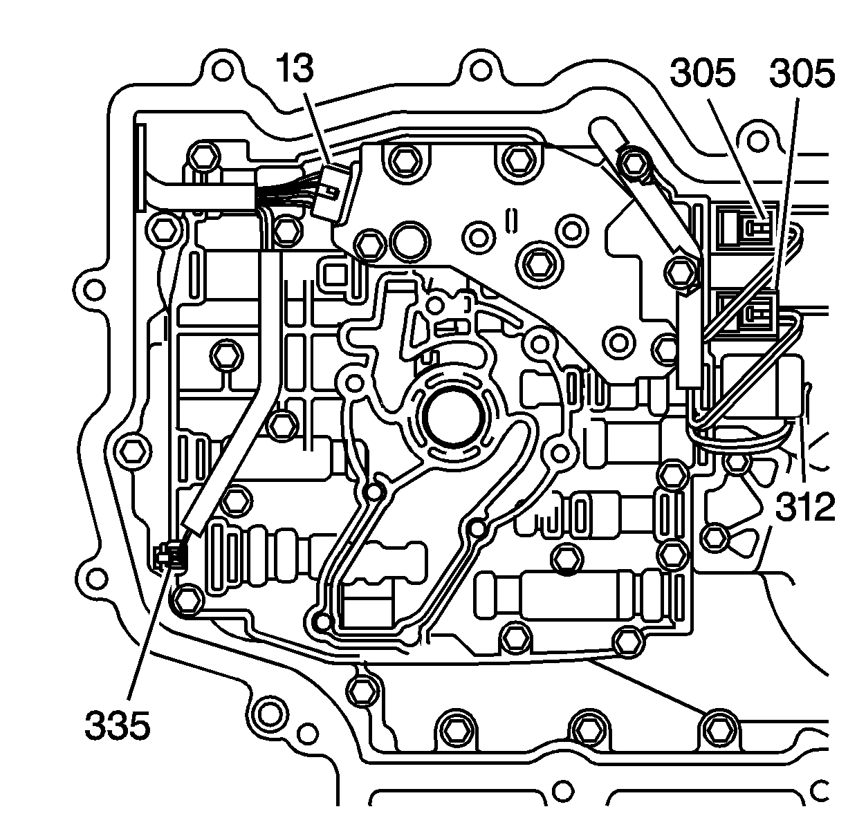
- Connect the wiring harness assembly to the following components:
| • | The TFP switch assembly (13) |
| • | The pressure control solenoid (312) (red connector) |
| | Important: The 1-2 shift solenoids wires are red and light green. The 2-3 shift solenoid wires are red and yellow.
|
| • | The 1-2 shift solenoid (305) (white connector) |
| • | The 2-3 shift solenoids (305) (white connectors) |
- Install the control valve body. Refer to
Control Valve Body Replacement.
- Install the transmission side cover. Refer to
Control Valve Body Cover Replacement.
Important: It is recommended that transmission adaptive pressure (TAP) information be reset.
Resetting the TAP values using a scan tool will erase all learned values in all cells. As a result, the engine control module
(ECM), powertrain control module (PCM) or transmission control module (TCM) will need to relearn TAP values. Transmission performance may be affected as new TAP values are learned.
- Reset the TAP values. Refer to
Transmission Adaptive Functions.


