Removal Procedure
- Place the steering wheel in the straight forward position.
- Remove the steering column opening filler. Refer to Steering Column Opening Filler Replacement.
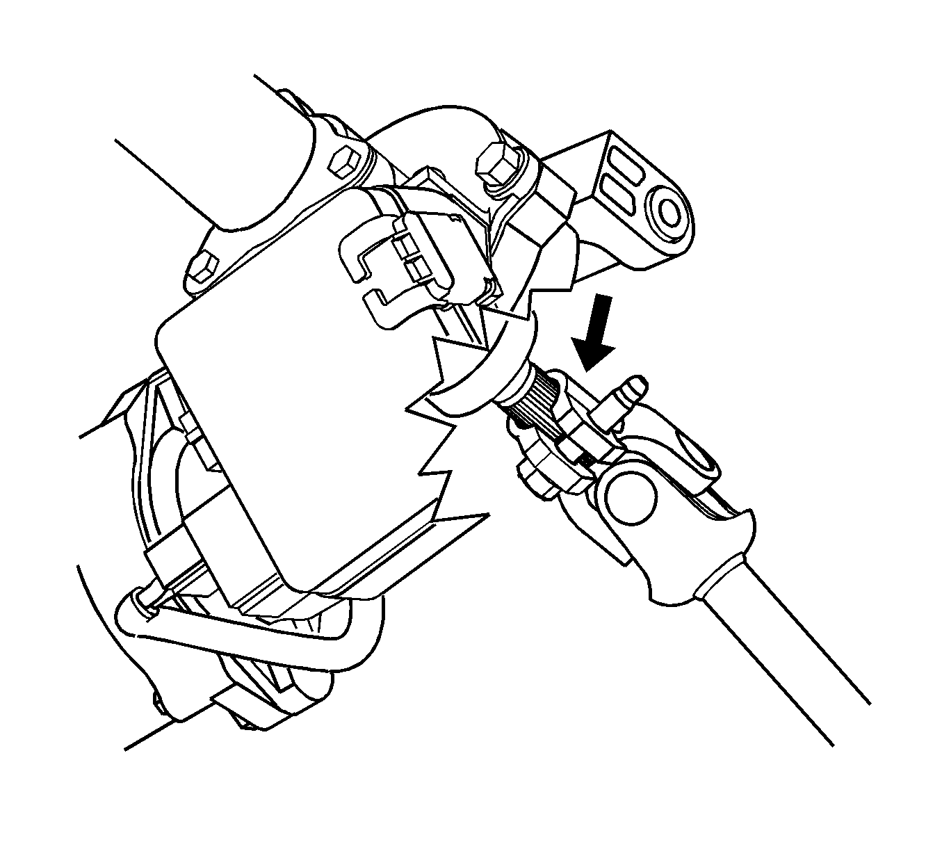
- Disconnect any electrical connectors as needed.
- Place scribe marks on the intermediate steering shaft and the steering column shaft.
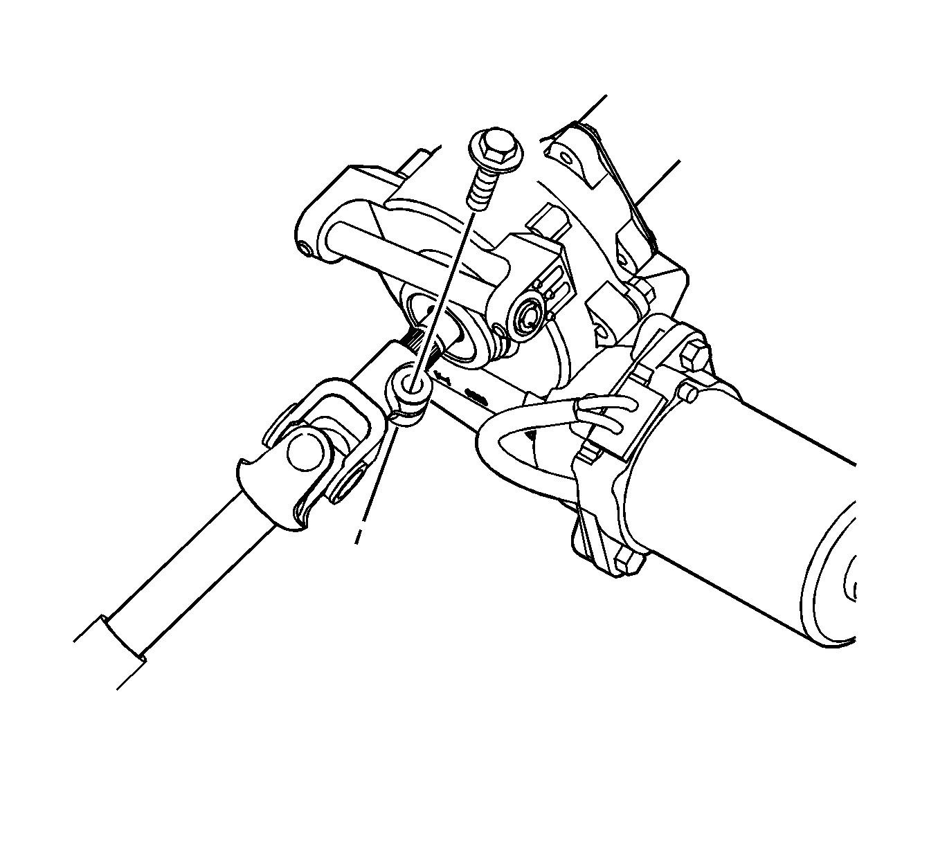
- Remove the intermediate steering shaft bolt at the steering column and discard the bolt.
- Separate the intermediate steering shaft from the steering column.
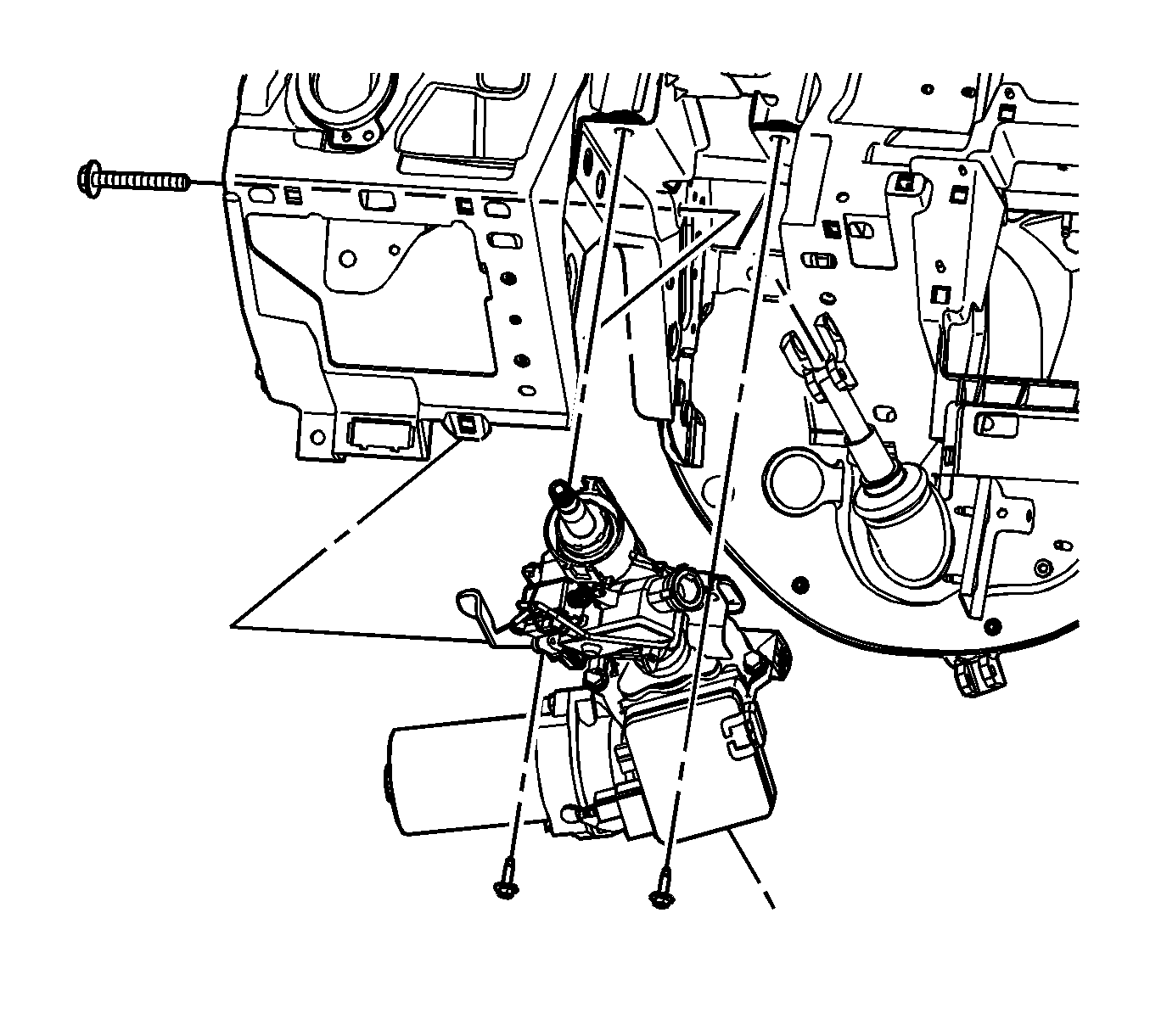
- Remove the steering column lower support bracket bolt.
- Remove the steering column upper support bracket bolts.
- Remove the steering column from the vehicle.
- Transfer any parts as needed.
Important: Ensure the front wheels are in the straight ahead position and the steering wheel is centered in order to mark the intermediate steering shaft position properly.

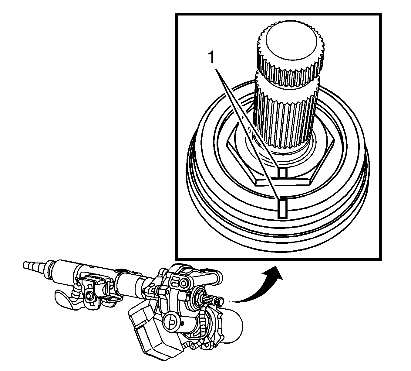
Important: The end of the steering column shaft has 2 divots machined into it. Place a scribe mark on the intermediate steering shaft matching one of these divots. This scribe mark will be needed for the proper alignment of either an old or new steering column.


Installation Procedure
- If you are installing a NEW steering column, align the manufacturer match marks (1) on the lower shaft.
- If you are installing a NEW steering column, copy the scribe marks from the old column to the new column.
- Position the steering column in the vehicle.
- Start the steering column lower and upper support bracket bolts.
- Tighten the steering column upper and lower support bracket bolts using the following order:
- Tighten the steering column lower support bracket bolt to 25 N·m (18 lb ft).
- Tighten the right side steering column upper support bracket bolt to 25 N·m (18 lb ft).
- Tighten the left side steering column upper support bracket bolt to 25 N·m (18 lb ft).
- Align the scribed mark on the intermediate steering shaft to the correct divot on the steering column shaft.
- Connect the intermediate steering shaft to the steering column shaft.
- Install a NEW intermediate steering shaft bolt.
- Connect any electrical connectors as needed.
- Install the steering column opening filler. Refer to Steering Column Opening Filler Replacement.
- If equipped with RPO JL4, calibrate the steering angle sensor. Refer to Control Module References.


Notice: Refer to Fastener Notice in the Preface section.
Tighten
Important: Failure to align the scribed mark on the old or new steering column may result in an off-center steering wheel. Ensure that the correct divot on the steering column is aligned with the scribe mark made previously.

Tighten
Tighten the bolt to 34 N·m (25 lb ft).
