For 1990-2009 cars only
Removal Procedure
- Raise and support the vehicle. Refer to Lifting and Jacking the Vehicle.
- Remove the wheel. Refer to Tire and Wheel Removal and Installation.
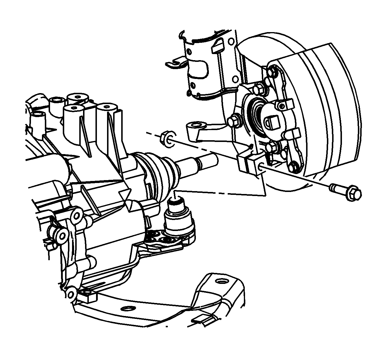
- Remove the ball stud to steering knuckle pinch bolt and nut.
- Separate the ball stud from the steering knuckle.
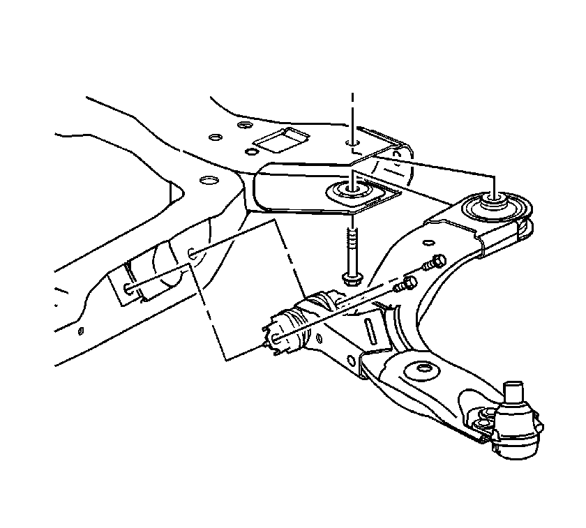
- Remove the rear frame bolt.
- Remove the control arm to frame bolts.
- Remove the control arm from the frame.

Caution: Do not free the ball stud by using a pickle fork or a wedge-type tool. Damage to the seal or bushing may result.

Installation Procedure
- Insert the rear portion of the control arm into the frame.
- Loosely install the rear frame bolt.
- Lower the control arm and insert the ball stud into the steering knuckle.
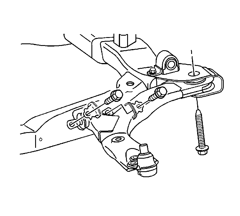
- Install the fore/aft movement limiting brackets onto the control arm forward bushing.
- Install both control arm to frame bolts.
- Tighten the rear frame bolt.
- Install the ball stud pinch bolt and nut.
- First Pass: Tighten the nut to 50 N·m (37 lb ft).
- Reverse nut 3/4 turn
- Second Pass: Tighten the nut to 50 N·m (37 lb ft) + 30 degrees.
- Install the wheel. Refer to Tire and Wheel Removal and Installation.
- Lower the vehicle.
- Road test the vehicle in order to test for leads or pulls. If leads or pulls are present refer to Wheel Alignment Measurement.


Note: The control arm contains 2 fore/aft movement limiting brackets. Failure to install these brackets will result in abnormal handling characteristics.
Caution: Refer to Fastener Caution in the Preface section.
Tighten
Tighten the bolts to 55 N·m (41 lb ft).
Tighten
Tighten the bolt to 100 N·m plus 180 degrees (74 lb ft) plus 180 degrees.

Note: The torque sequence must be followed in the order that is listed.
Tighten
