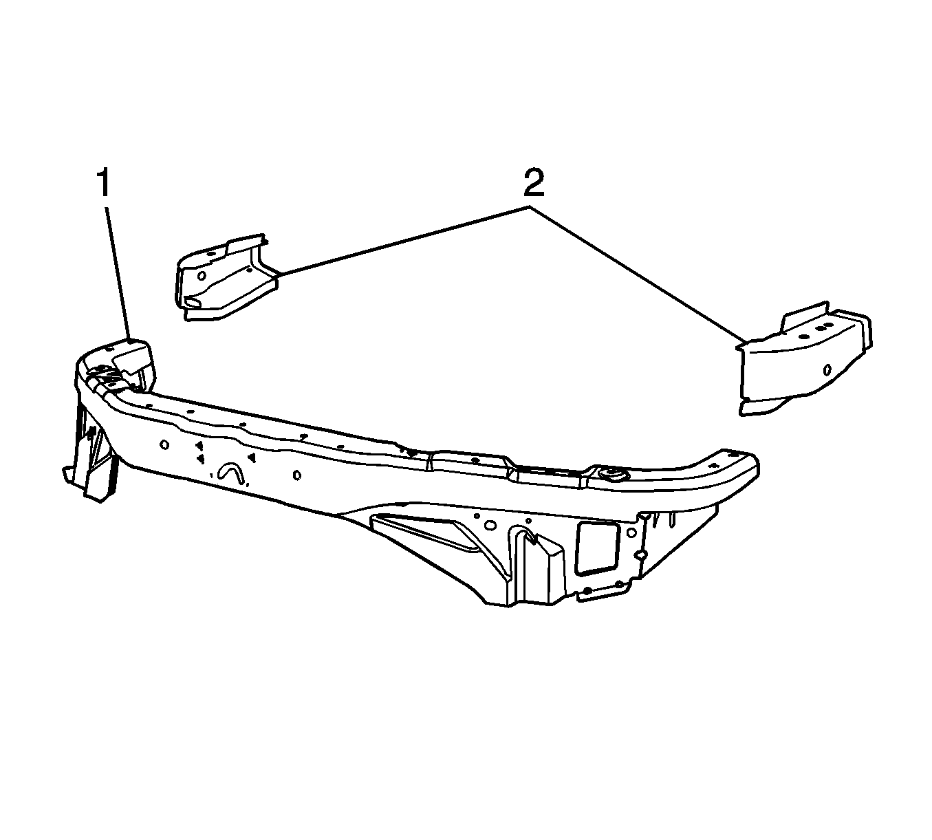
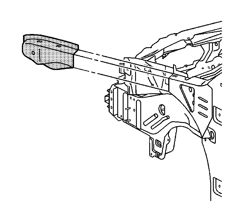
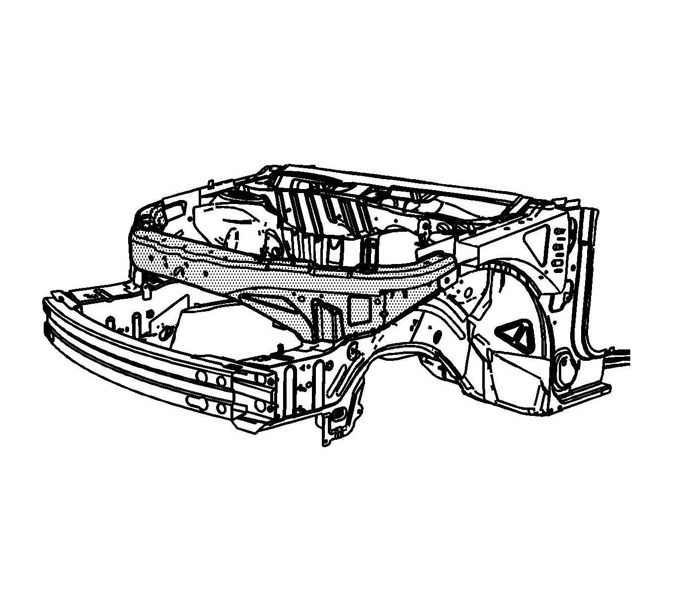
Note: Replacement of the tie bar requires partial removal of the upper side rails. The tie bar (1) and upper side rail service parts (2) are included in a kit for efficient installation. If the damage permits, locate and remove the front portion of the upper side rails in the location described in this procedure, and install the upper side rail service parts. If the damage does not permit the use of the upper side rail service parts (2), the entire upper side rail must be replaced. This procedure must be performed on both sides of the vehicle. The procedure below only illustrates the driver's side.
Removal Procedure
- Disable the SIR system. Refer to SIR Disabling and Enabling.
- Disconnect the negative battery cable. Refer to Battery Negative Cable Disconnection and Connection.
- Remove all related panels and components.
- Repair as much of the damage as possible to factory specifications. Refer to Dimensions - Body.
- Note the location and remove the sealers and anti-corrosion materials from the repair area, as necessary. Refer to Anti-Corrosion Treatment and Repair.
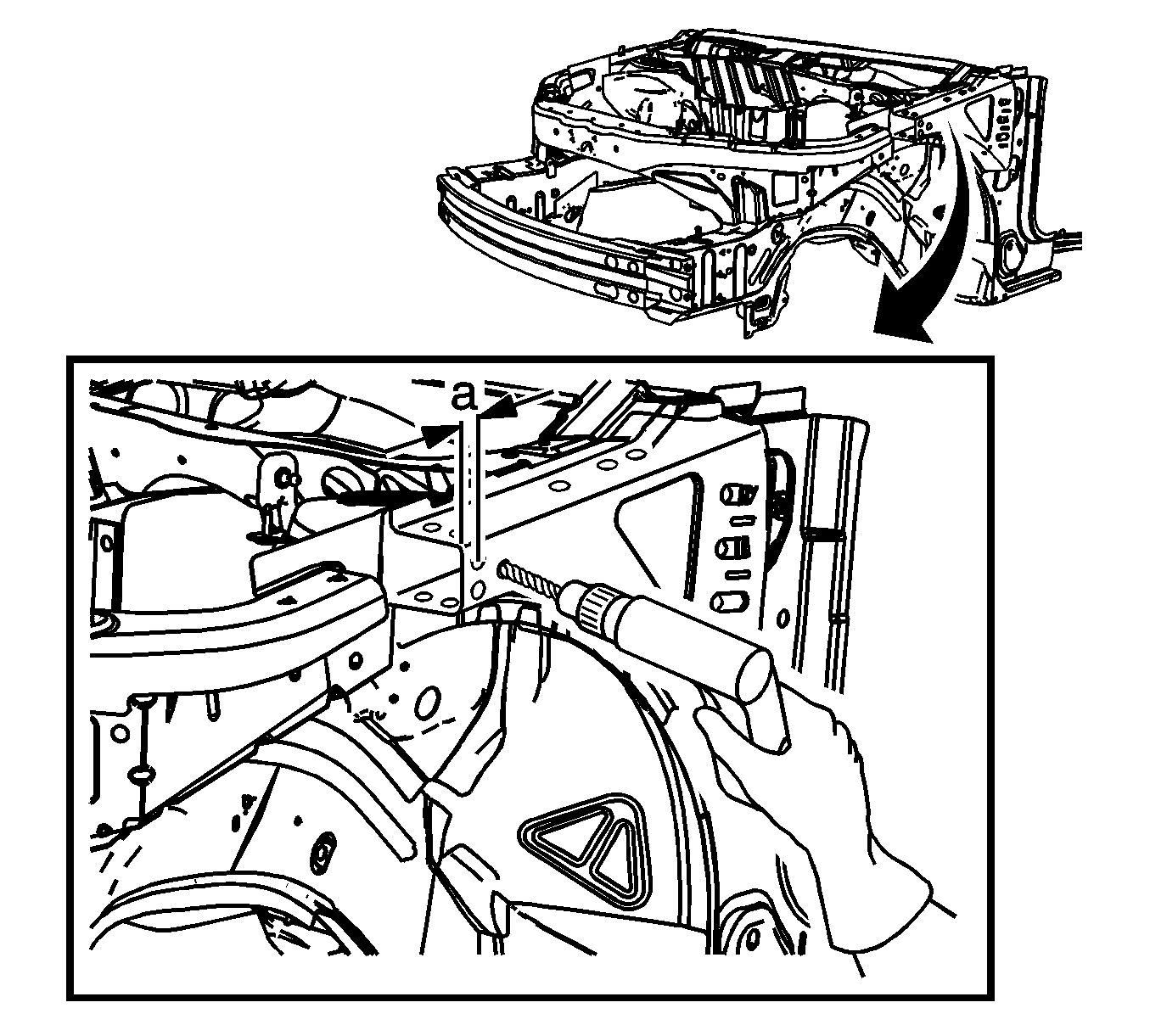
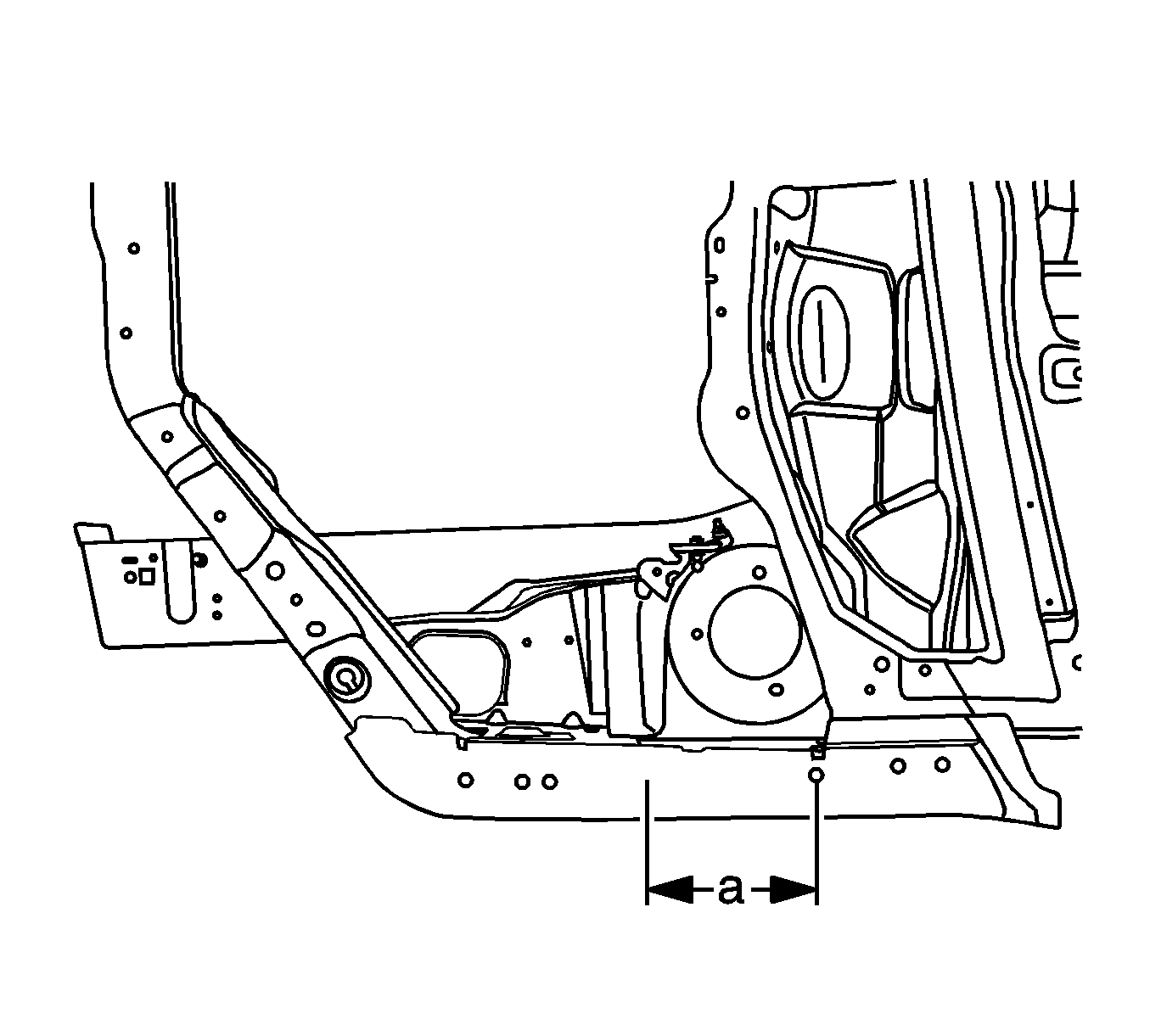
- On the driver side upper side rail, measure (a) 225 mm (8 7/8 in) from the center forward hood hinge mounting hole. Scribe a line.
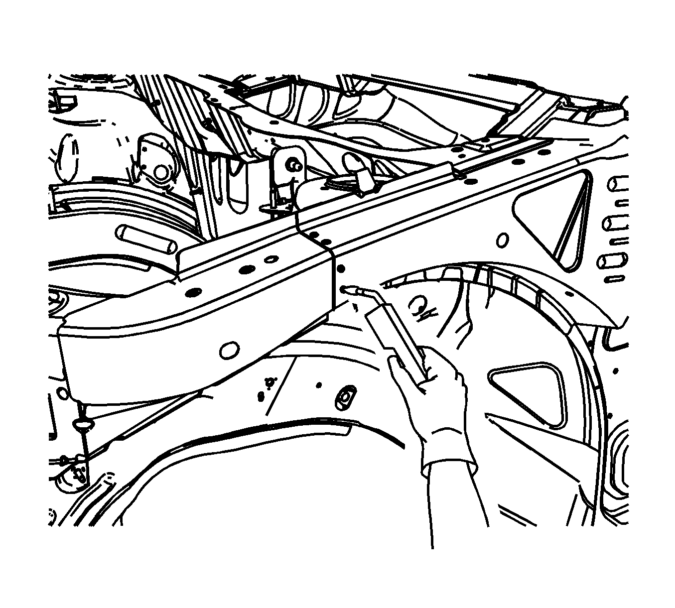
- Using the mark made in the previous step as a starting point, use a sliding square to transfer a line on the top, the side, and the bottom of the rail.
- Locate and drill out all spot welds on the upper side rail forward of the scribed line. Note the number and location of the spot welds for installation of the upper side rail.
- Cut the original upper side rail at the scribed location.
- Remove the front portion of the upper side rail.
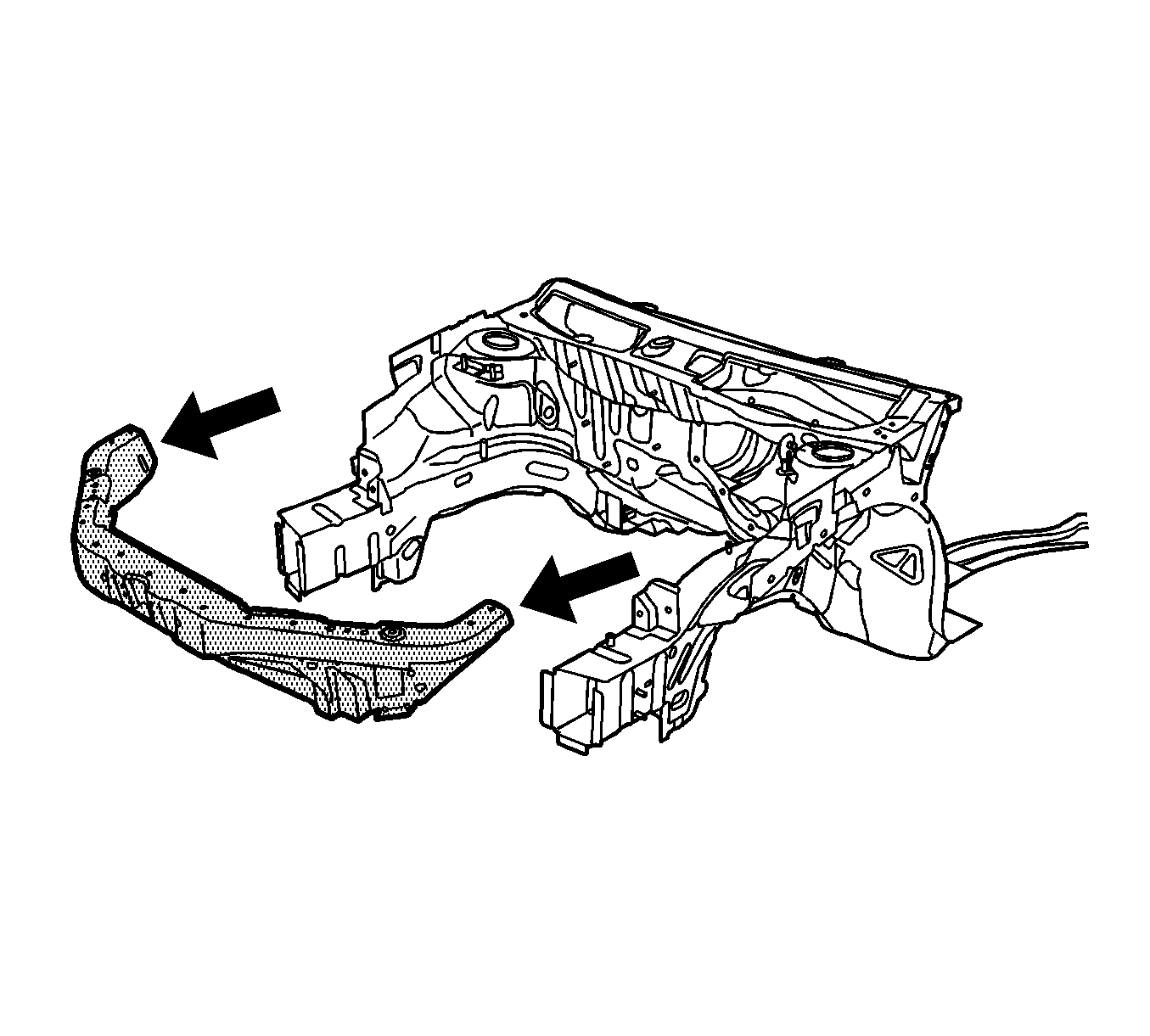
- Locate and drill out all factory spot welds on the tie bar assembly. Note the number and location of the welds for installation of the tie bar.
- Remove the damaged tie bar.
Warning: Refer to Approved Equipment for Collision Repair Warning in the Preface section.
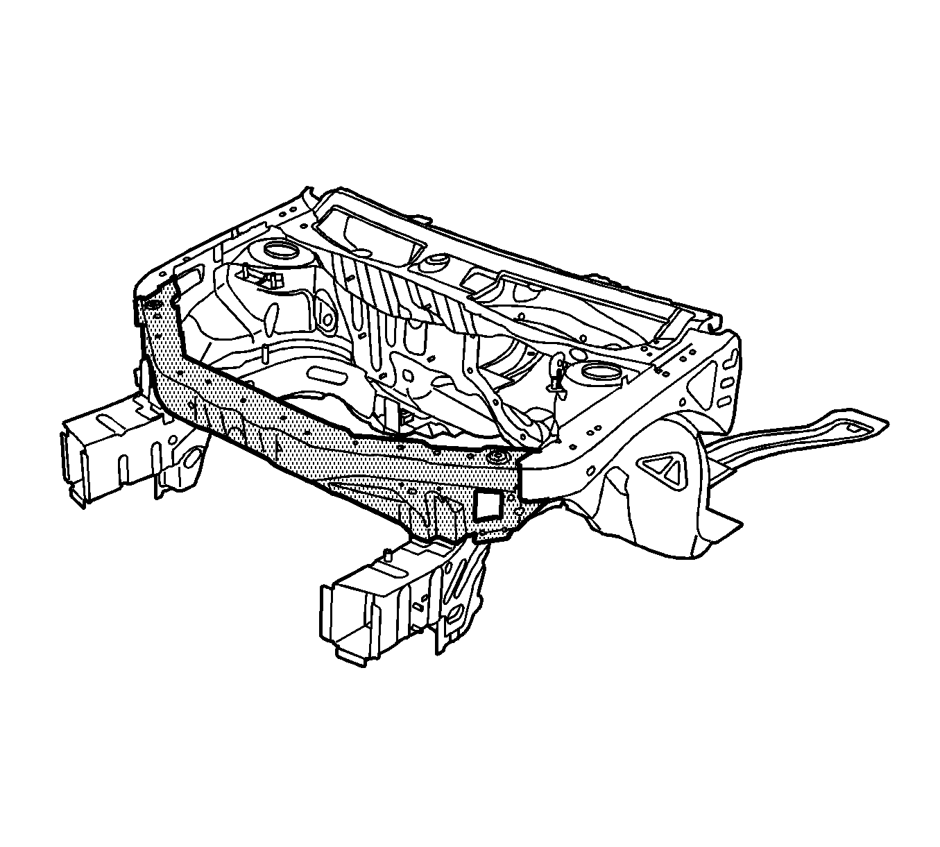
Note: The following steps are necessary to gain access to the spot welds at the tie bar ends. Repeat each step on the opposite end of the tie bar.
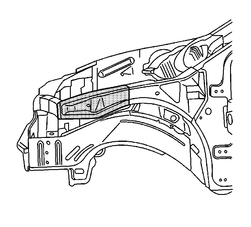
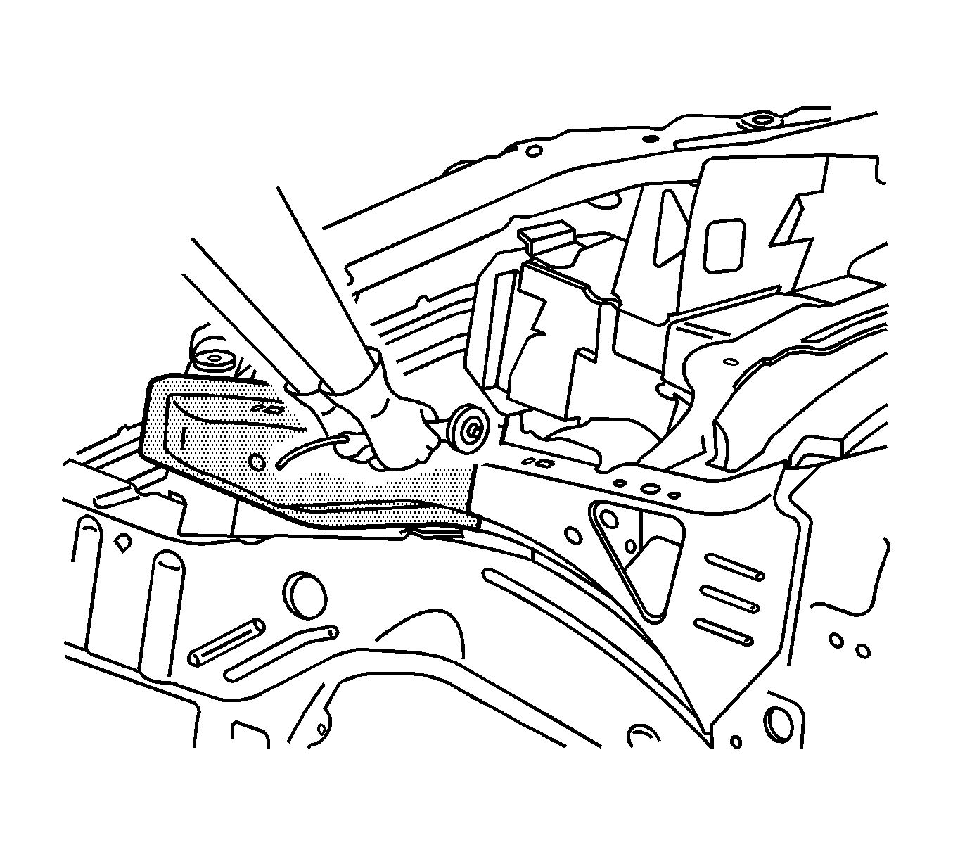
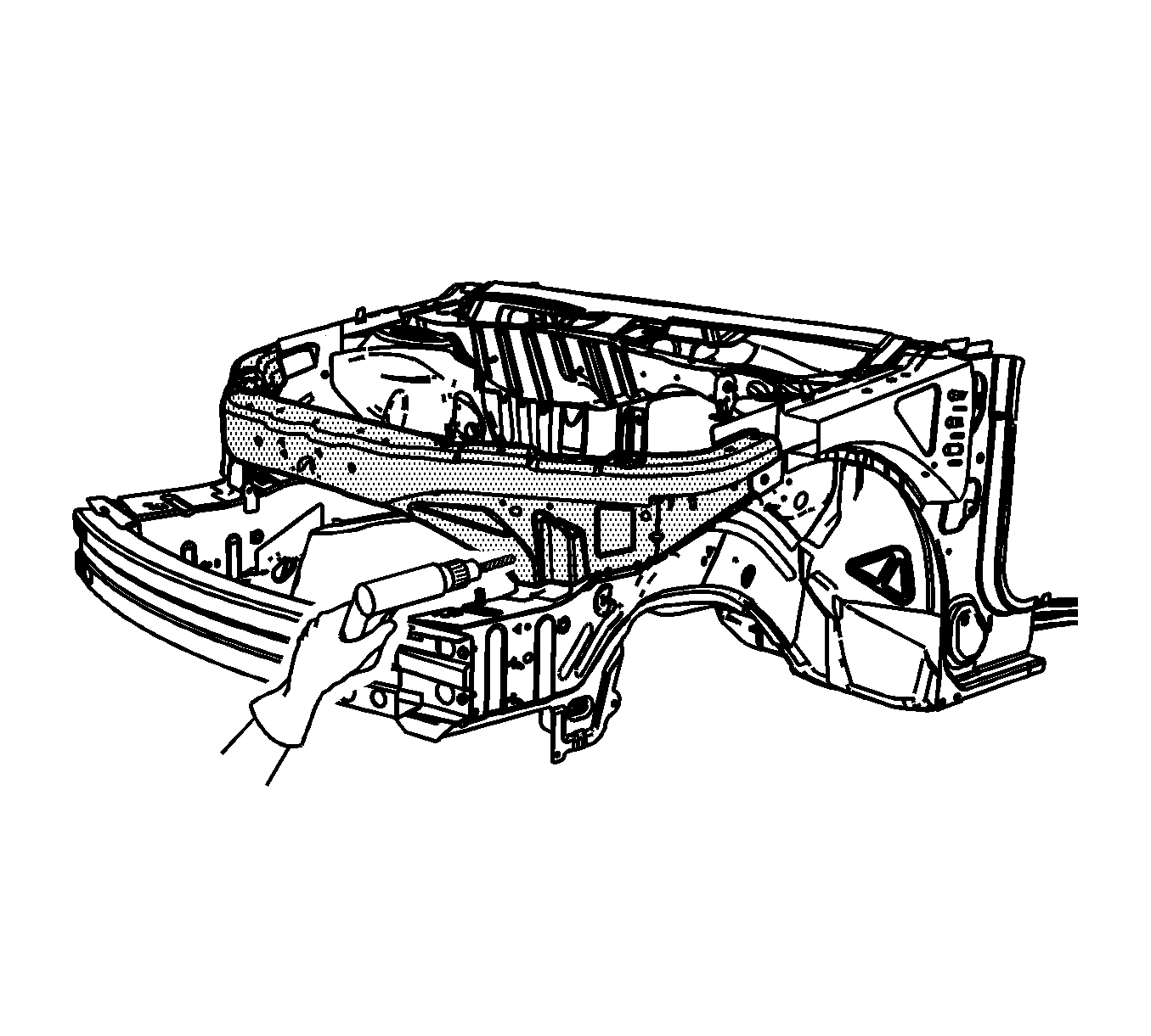
Note: Do not damage any inner panels or reinforcements.
Installation Procedure
- Drill 8 mm (5/16 in) plug weld holes in the front upper tie bar, as necessary, in the locations noted from the original panel.
- Prepare all mating surfaces, as necessary.
- Apply GM-approved Weld-Thru Coating or equivalent to all mating surfaces. Refer to Anti-Corrosion Treatment and Repair.
- Use 3-dimensional measuring equipment to position the front upper tie bar to the vehicle. Clamp the front upper tie bar in place.
- Plug weld accordingly.
- Use 3-dimensional measuring equipment to position the upper side rail service part to the vehicle to ensure that the service and factory part line up. There should be a 1.5 mm (1/16 in) gap between the 2 parts. Once the proper fit has been achieved, proceed to step 7.
- Drill six 8 mm (5/16 in) plug weld holes (a) 12 mm (1/2 in) rearward, from the edge of the remaining portion of the upper side rail on the vehicle. The 6 plug-weld holes should be spaced so that there are 2 on the top, side and bottom.
- Drill 8 mm (5/16 in) plug weld holes in the upper side rail, as necessary, in the locations noted from the original panel.
- Prepare all mating surfaces, as necessary.
- Apply GM-approved Weld-Thru Coating or equivalent to all mating surfaces. Refer to Anti-Corrosion Treatment and Repair.
- Use 3-dimensional measuring equipment to position the upper side rail service part to the vehicle. Clamp the rail in place.
- Plug weld the 6 plug-weld holes located in the upper side rail on the vehicle.
- Plug weld the remaining plug weld holes, as noted, from the factory spot welds.
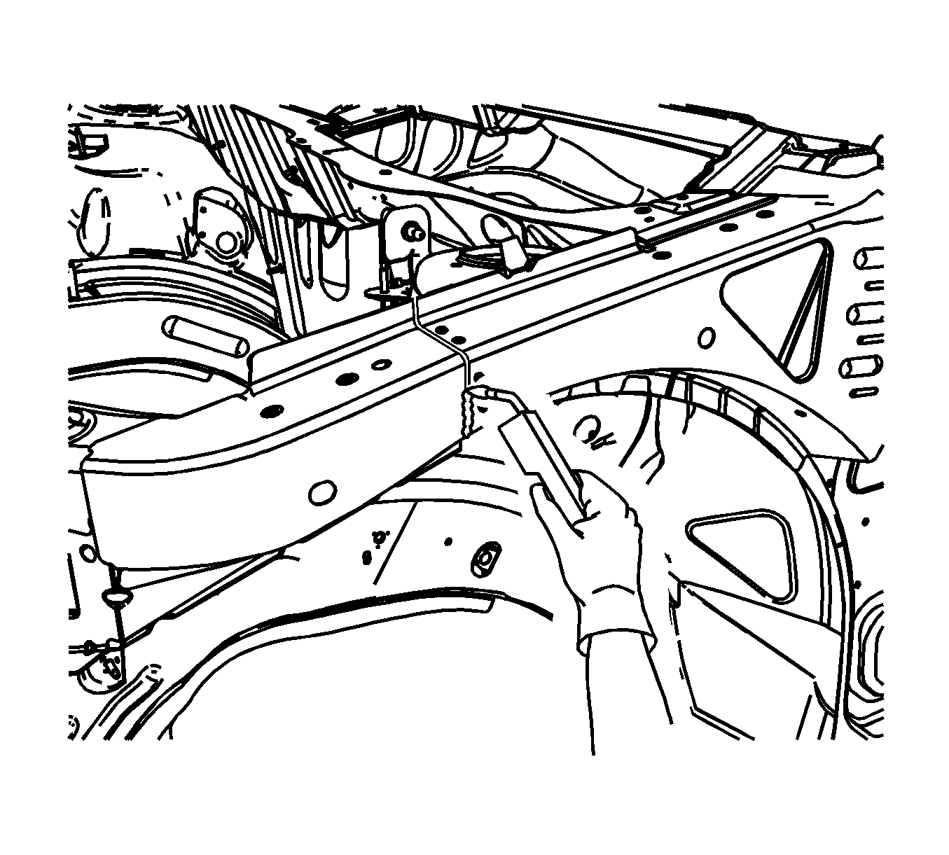
- To create a solid weld with minimum heat distortion, make 25 mm (1 in) stitch welds along the seam with 25 mm (1 in) gaps between them. Then go back and complete the stitch weld.
- Clean and prepare all welded surfaces.
- Apply the sealers and anti-corrosion materials to the repair area, as necessary. Refer to Anti-Corrosion Treatment and Repair.
- Paint the repair area. Refer to Basecoat/Clearcoat Paint Systems.
- Install all related panels and components.
- Connect the battery negative cable. Refer to Battery Negative Cable Disconnection and Connection.
- Enable the SIR system. Refer to SIR Disabling and Enabling.
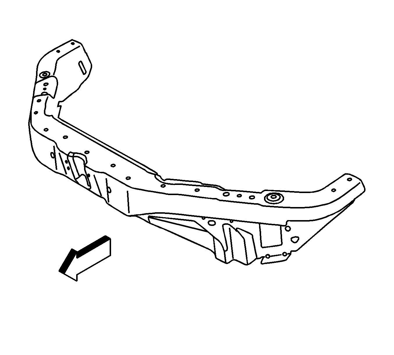
Note: If the location of the original plug weld holes cannot be determined, space the plug weld holes every 40 mm (1 1/2 in) apart.
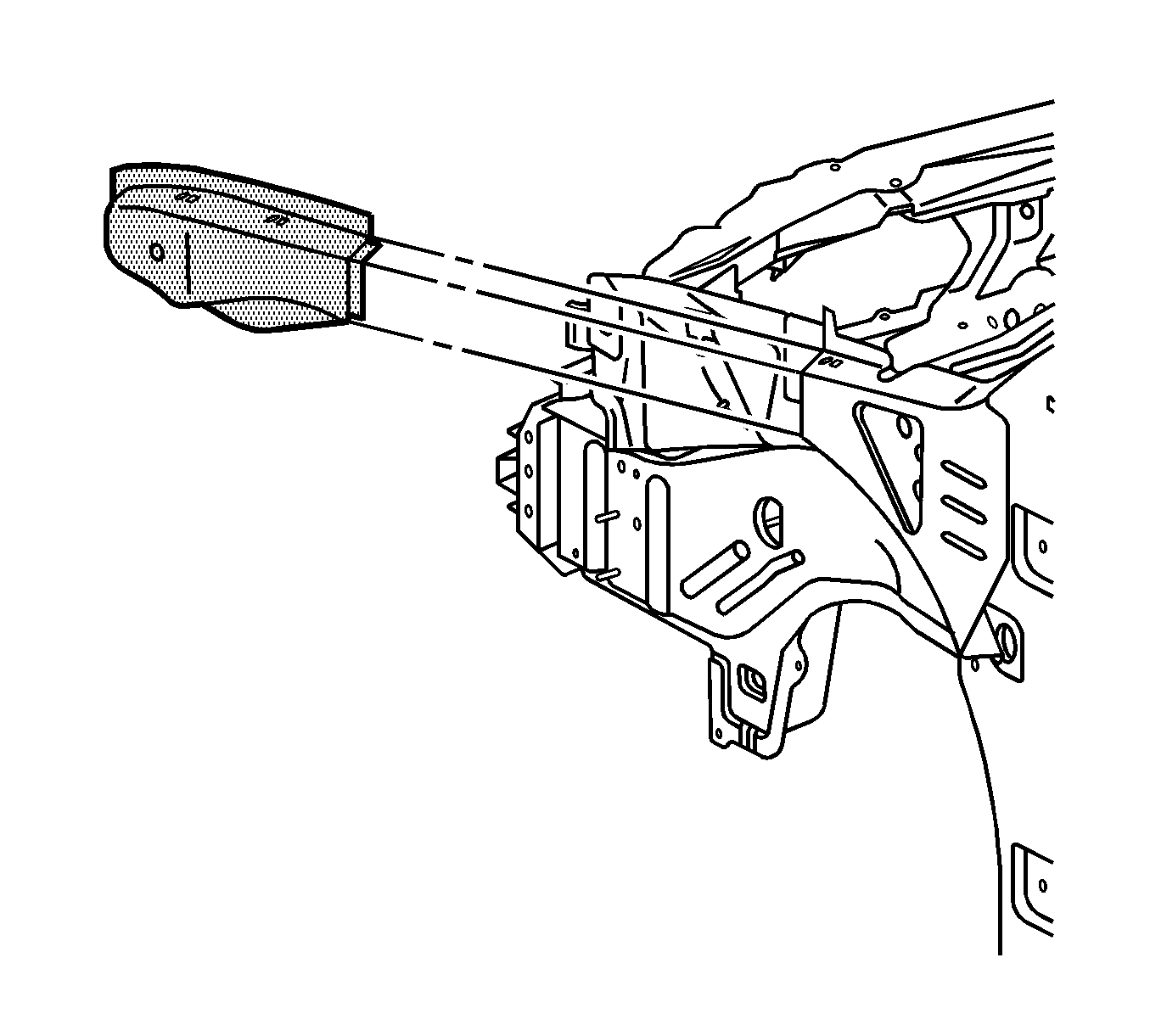
Note: The upper side rail service part comes with the backing plate installed. The backing plate on the service part will slide inside the remaining portion of the upper side rail on the vehicle.
