For 1990-2009 cars only
Special Tools
| • | J 39400-A Halogen Leak Detector |
| • | J 38185 Hose Clamp Pliers |
Warning: With a pressurized cooling system, the coolant temperature in the radiator can be considerably higher than the boiling point of the solution at atmospheric pressure. Removal of the surge tank cap, while the cooling system is hot and under high pressure, causes the solution to boil instantaneously with explosive force. This will cause the solution to spew out over the engine, the fenders, and the person removing the cap. Serious bodily injury may result.
Removal Procedure
- Disconnect the negative battery cable. Refer to Battery Negative Cable Disconnection and Connection.
- Recover the refrigerant. Refer to Refrigerant Recovery and Recharging.
- Drain the cooling system. Refer to Cooling System Draining and Filling.
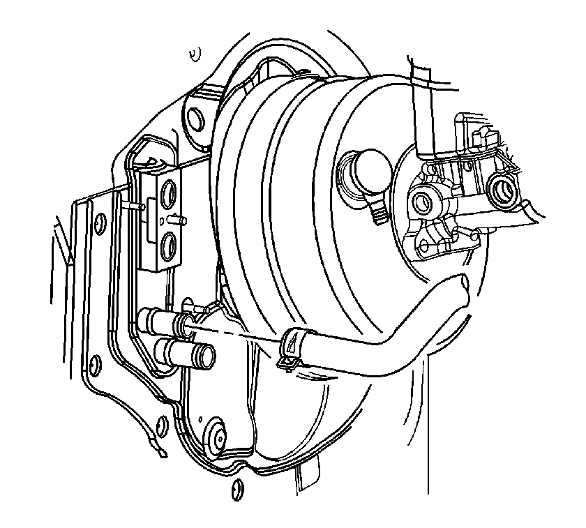
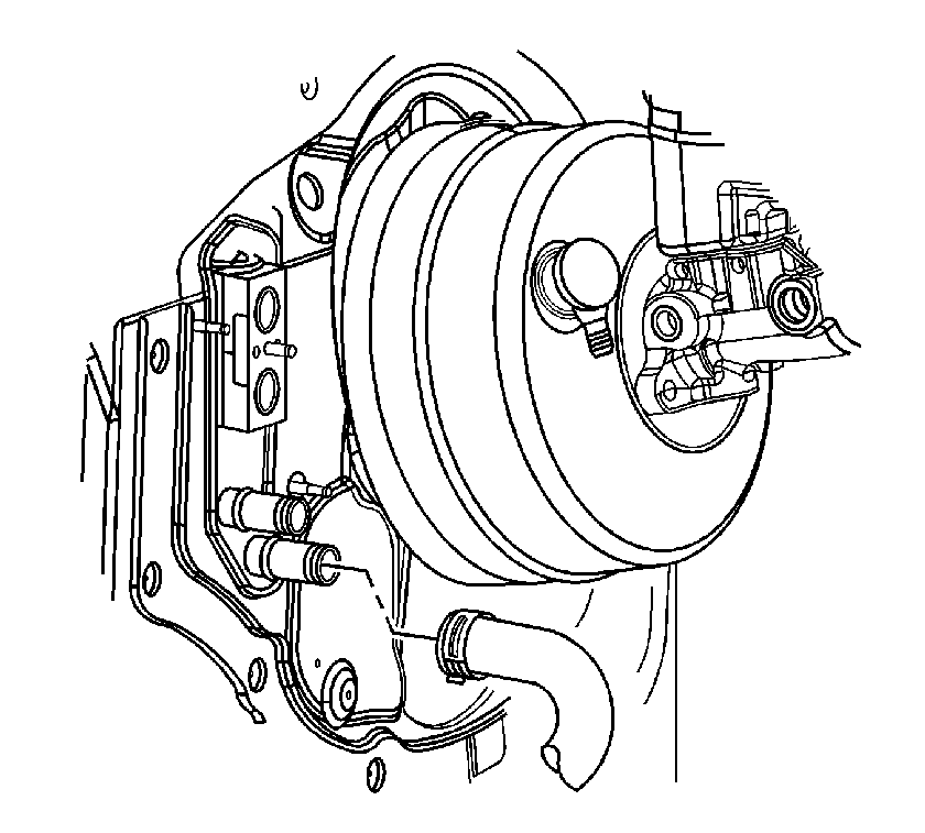
- Reposition the heater outlet hose clamp at the heater core using J 38185 .
- Remove the heater outlet hose from the heater core.
- Position the hose upright against the front of dash.
- Reposition the heater inlet hose clamp at the heater core using J 38185 .
- Remove the heater inlet hose from the heater core.
- Position the hose upright against the front of dash.
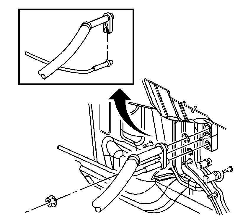
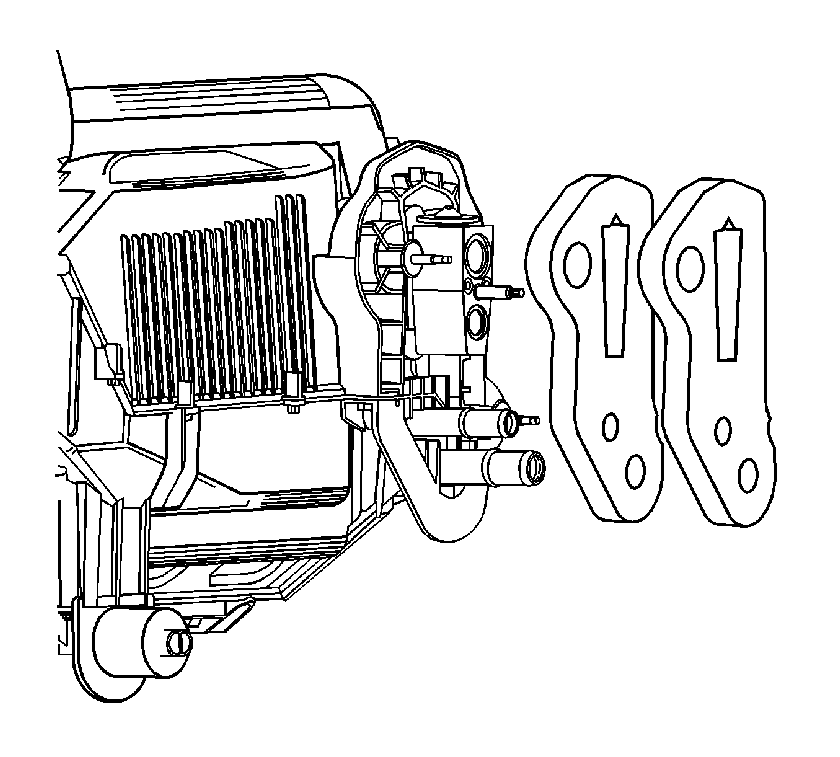
- Remove the condenser tube and evaporator hose from the thermal expansion valve (TXV).
- Remove and discard the seal washers.
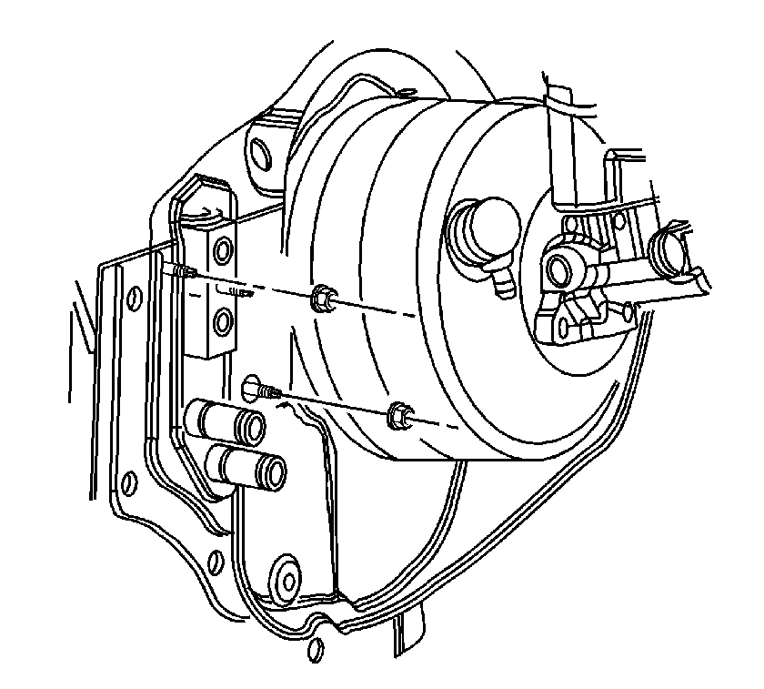
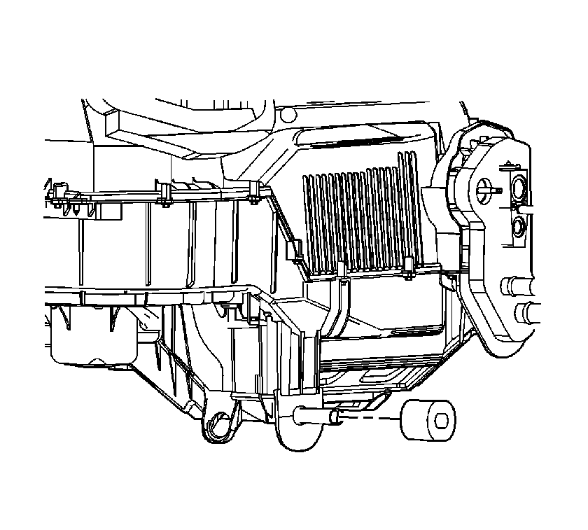
- Remove the HVAC module nuts from the front of dash.
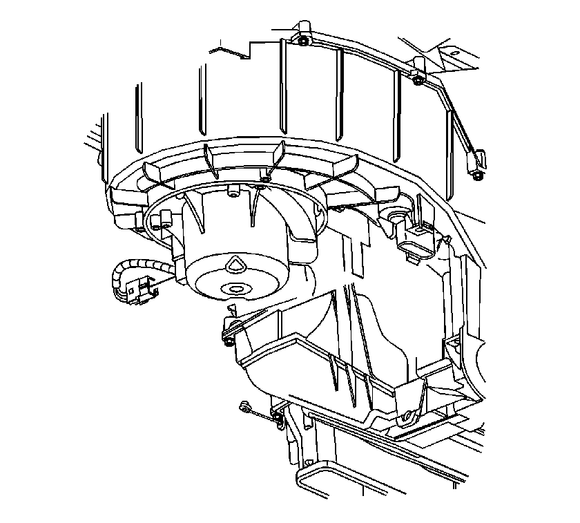
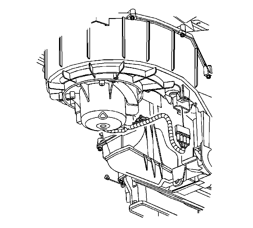
- Disconnect the blower motor connector.
- Disconnect the blower motor resistor electrical connector.
- Remove the instrument panel (I/P) tie bar. Refer to Instrument Panel Tie Bar Replacement.
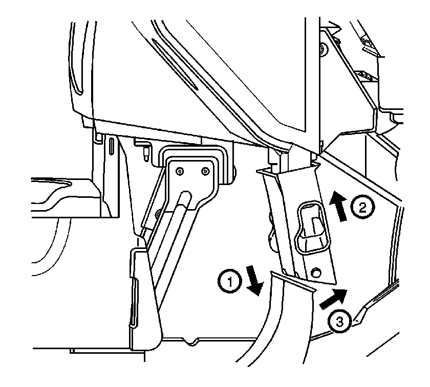
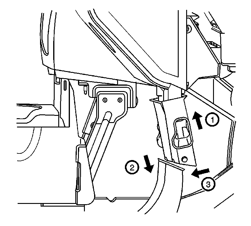
- Raise the center floor outlet duct while pushing the floor ducts down to disengage the ducts.
- Rotate the center floor outlet duct forward in the vehicle and pull down to disengage the duct from the HVAC module.
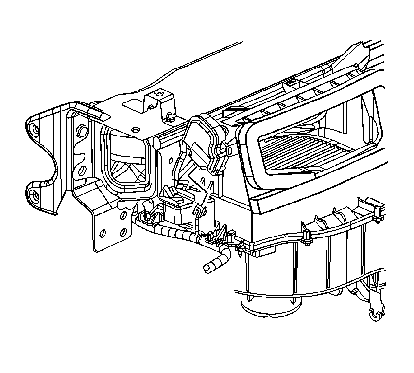
- Disconnect the recirculation actuator electrical connector.
- Remove the HVAC module from the vehicle.
Installation Procedure
- Replace the drain tube seal.
- Replace the front of dash seal.
- Inspect and replace the HVAC module seals if damaged:
- Place the HVAC module in the vehicle. Align the HVAC module drain tube and front of dash studs to the vehicle.
- Install the HVAC module nuts to the front of dash.
- Connect the recirculation actuator electrical connector.
- Align the center floor duct with the HVAC module.
- Push the center floor duct up while rotating rearward in the vehicle to install on the HVAC module.
- Push down on the floor duct while rotating the center floor outlet ducts to align the ducts.
- Slide the center floor outlet duct down into position in the floor ducts.
- Install the I/P tie bar. Refer to Instrument Panel Tie Bar Replacement.
- Connect the blower motor connector.
- Connect the blower motor resistor electrical connector.
- Install the heater outlet hose to the heater core.
- Reposition the hose clamp to secure the hose using J 38185 .
- Install the heater inlet hose to the heater core.
- Reposition the hose clamp to secure the hose using J 38185 .
- Install new sealing washers on the condenser tube and evaporator hose fittings.
- Install the condenser tube and evaporator hose to the TXV.
- Install the TXV nut.
- Evacuate and charge the refrigerant system. Refer to Refrigerant Recovery and Recharging.
- Leak test the fittings using the J 39400-A .
- Connect the negative battery cable. Refer to Battery Negative Cable Disconnection and Connection.
- Fill the cooling system. Refer to Cooling System Draining and Filling.
| • | The defrost duct seal |
| • | The HVAC module to cross car duct seal |
| • | The center air outlet duct seal |
| • | The center floor air outlet duct seal |
| • | The air inlet seal |
Caution: Refer to Fastener Caution in the Preface section.

Tighten
Tighten the nuts to 10 N·m (89 lb in).



Tighten
Tighten the nut to 20 N·m (15 lb ft).
