GM Service Manual Online
For 1990-2009 cars only
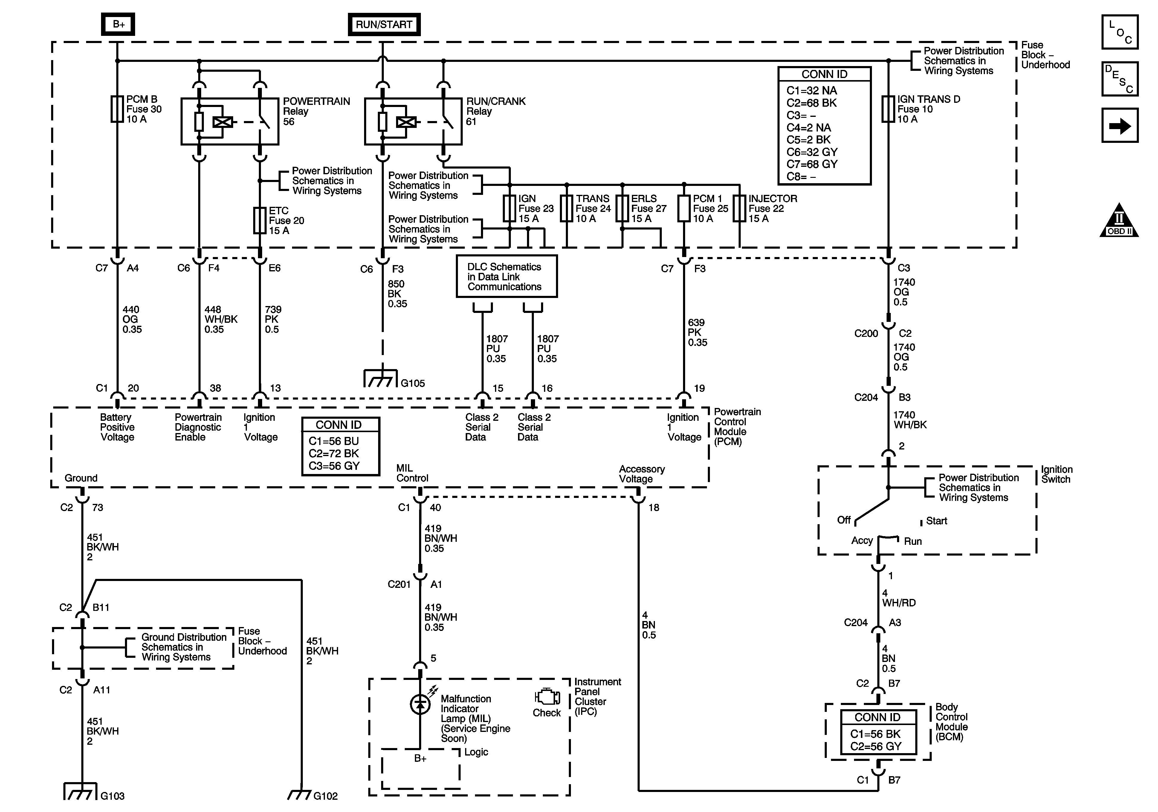
Figure 1:

Power, Ground, MIL, and DLC


Object Number: 1284771  Size: FS
Master Electrical Component List
Powertrain Control Module Description
5 Volt Reference
OBD II Symbol Description Notice
B+ Bus - Underhood Fuse Block
WIPER SW, PWR WDO, ETC, and 02 SENSOR Fuses
SIR, CRUISE/MISC, TRANS, BACK UP, and ABS Fuses
SPARE, IGN, and A/C COMP Fuses
Data Link Connector (DLC) Schematics
Splice Pack SP105 and G105 - 1 of 2
IGN TRANS D Fuse
G100, G104, G102, G103, and G101
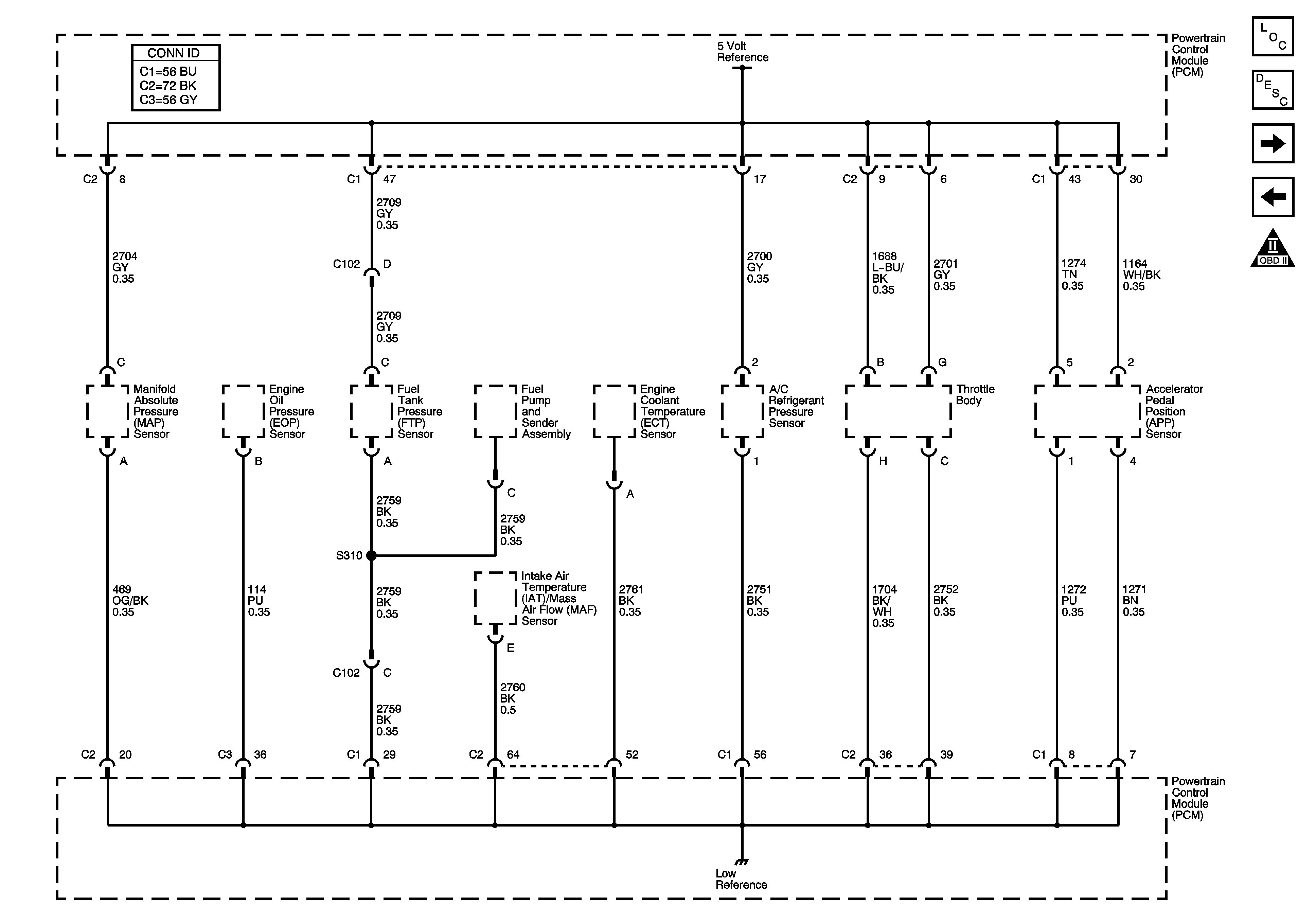
Figure 2:

5-Volt Reference


Object Number: 1284776  Size: FS
Master Electrical Component List
Powertrain Control Module Description
Engine Data Sensors
Power, Ground, MIL, and DLC
OBD II Symbol Description Notice
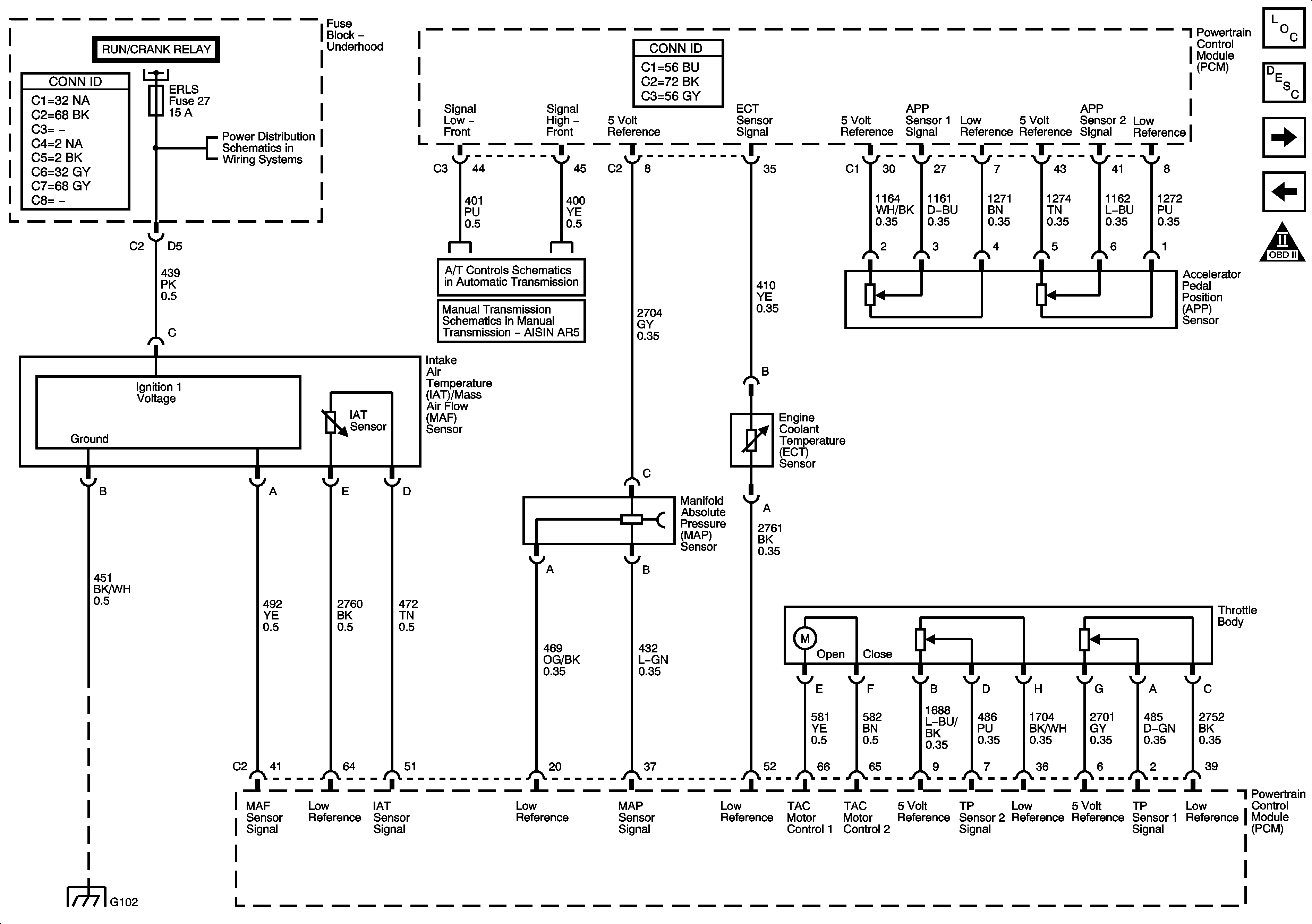
Figure 3:

Engine Data Sensors


Object Number: 1284778  Size: FS
Master Electrical Component List
Powertrain Control Module Description
Oxygen Sensors
5 Volt Reference
OBD II Symbol Description Notice
Power, Ground, MIL, and DLC
04 GMT355 Power Distribution Schematics - ERLS, FRT AXLE, PCM - I, and INJECTORS Fuses
TCC Brake/Cruise Release Switch and Vehicle Speed Sensor
04 GMT355 Manual Transmission Schematics
G300, G301, and G302
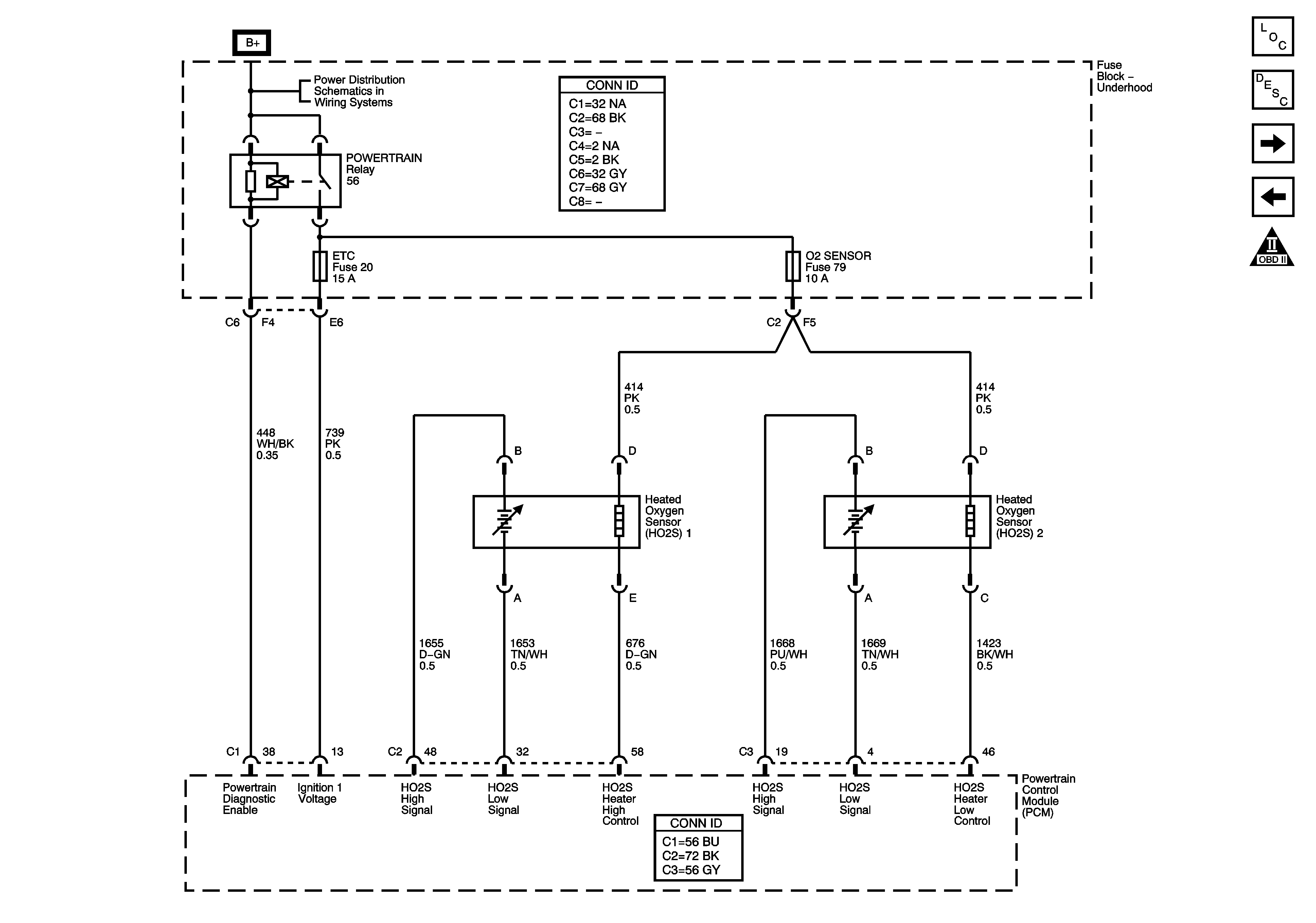
Figure 4:

Oxygen Sensors


Object Number: 1284780  Size: FS
Master Electrical Component List
Powertrain Control Module Description
Knock, CMP, CKP Sensors, and EGR
Engine Data Sensors
OBD II Symbol Description Notice
B+ Bus - Underhood Fuse Block
Figure 5:

Knock, CMP, CKP Sensors, and CMP Actuator Solenoid
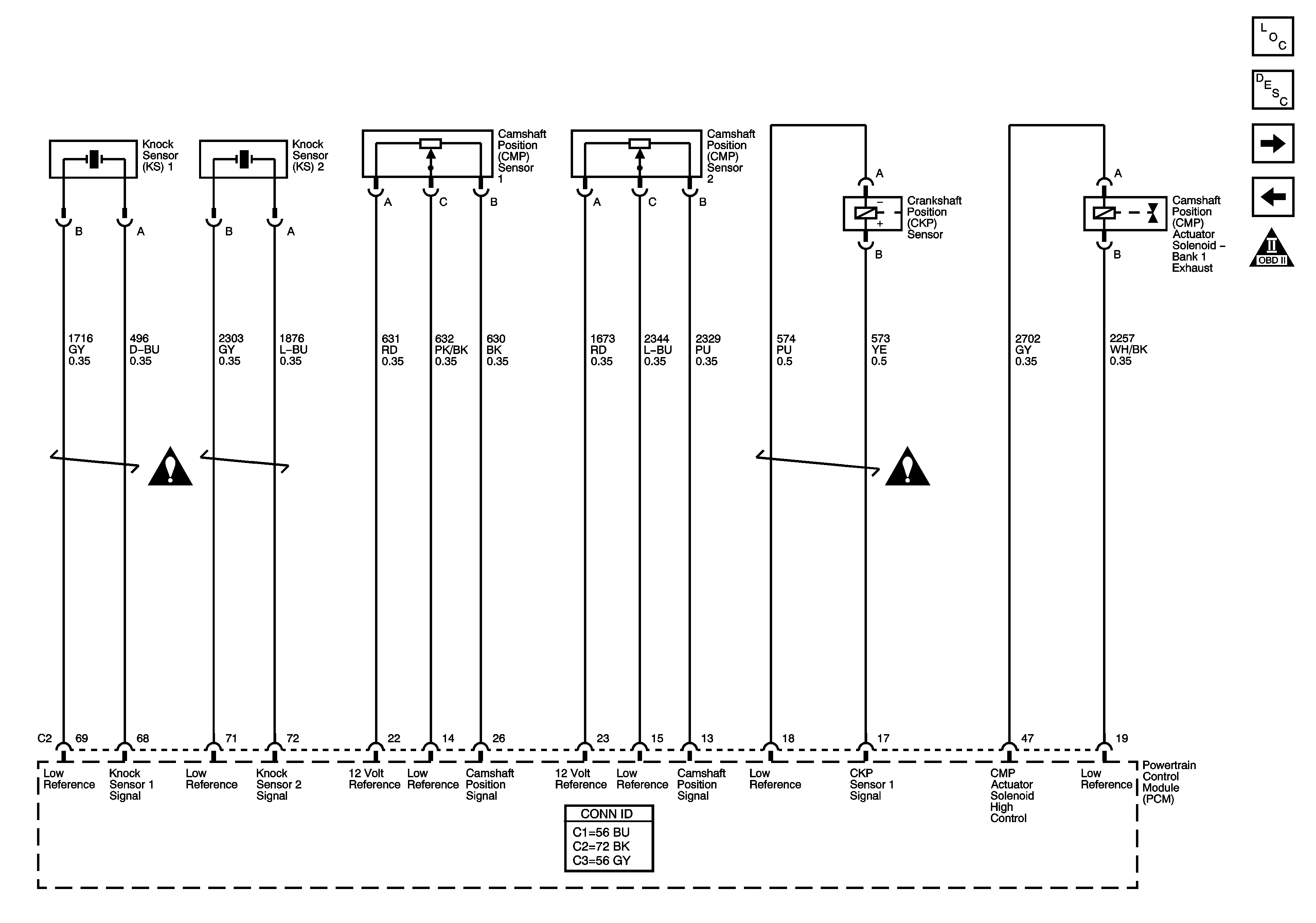

Object Number: 1284782  Size: FS
Master Electrical Component List
Powertrain Control Module Description
Ignition Controls
Oxygen Sensors
OBD II Symbol Description Notice
Engine Controls Schematic Icons
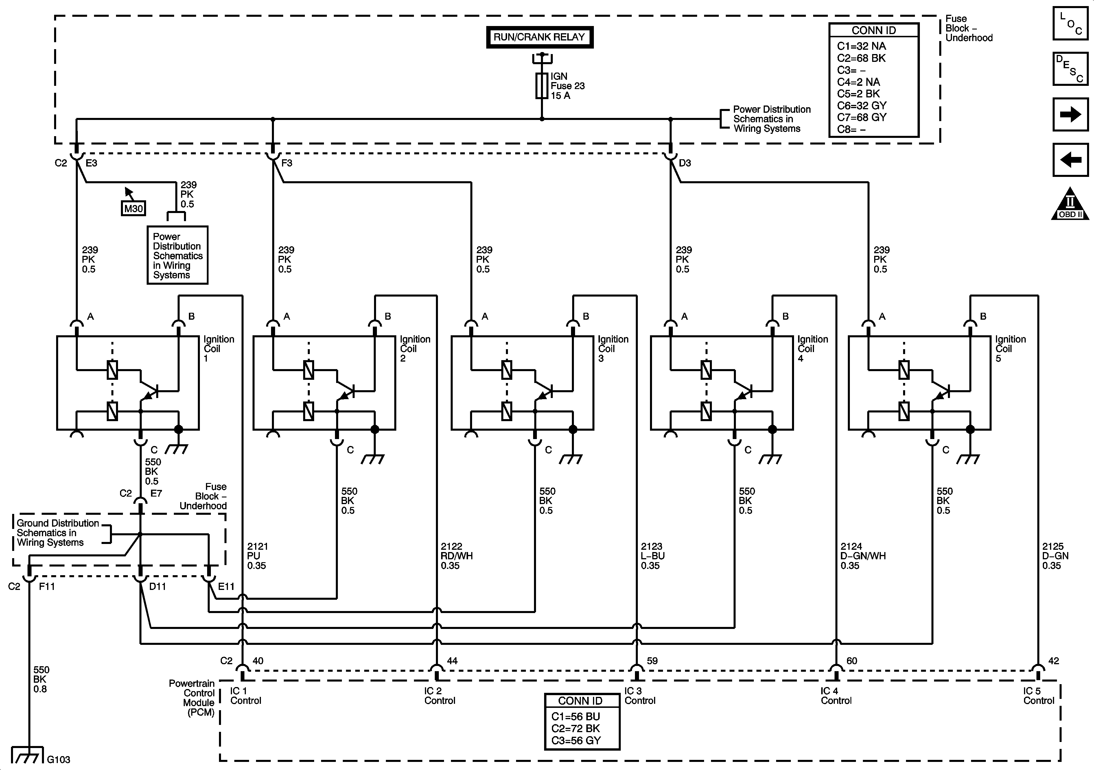
Figure 6:

Ignition Controls


Object Number: 1284784  Size: FS
Master Electrical Component List
Powertrain Control Module Description
Fuel Controls
Knock, CMP, CKP Sensors, and EGR
OBD II Symbol Description Notice
Power, Ground, MIL, and DLC
SPARE, IGN, and A/C COMP Fuses
G100, G104, G102, G103, and G101
Figure 7:

Fuel Controls


Object Number: 1284787  Size: FS
Master Electrical Component List
Powertrain Control Module Description
Fuel Injection Controls
Ignition Controls
OBD II Symbol Description Notice
B+ Bus - Underhood Fuse Block
Splice Pack SP105 and G105 - 1 of 2
Splice Pack SP105 and G105 - 2 of 2
Gages
Splice Pack SP105 and G105 - 1 of 2
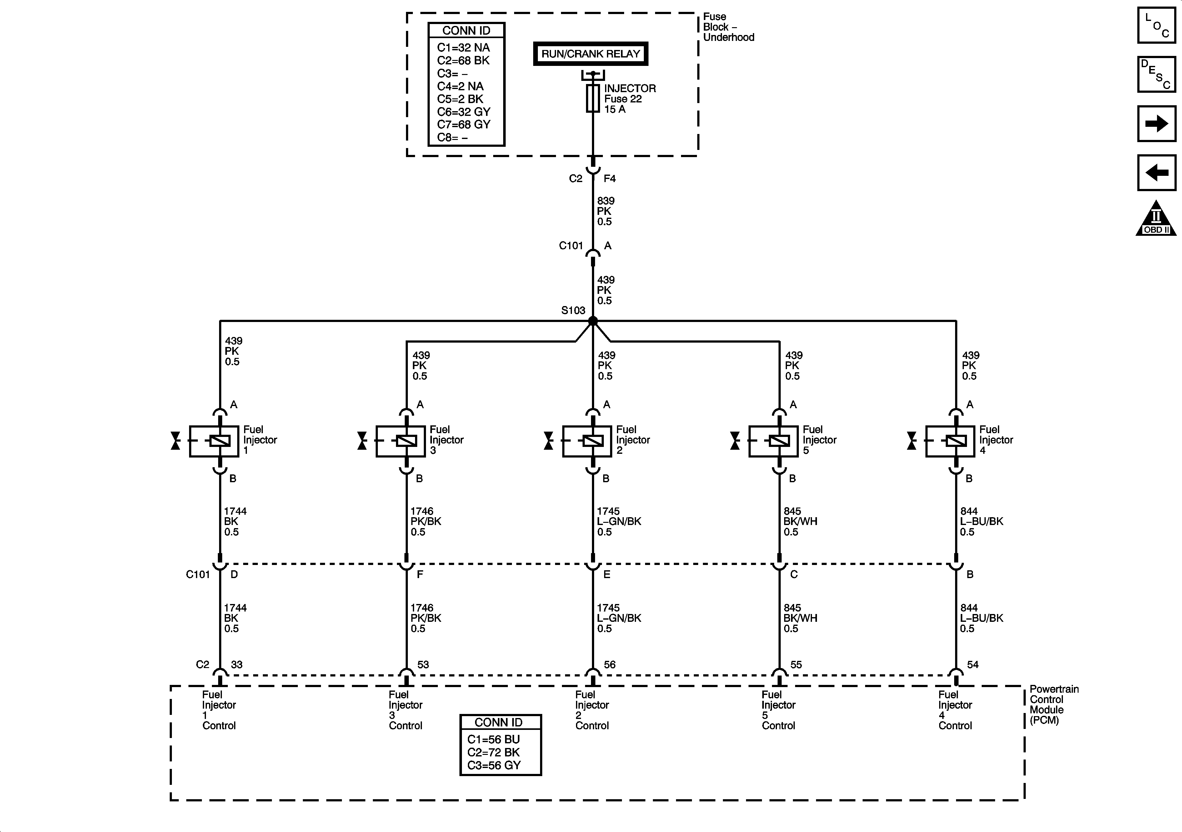
Figure 8:

Fuel Injection Controls


Object Number: 1284788  Size: FS
Master Electrical Component List
Powertrain Control Module Description
Fuel and EVAP Controls
Fuel Controls
OBD II Symbol Description Notice
Power, Ground, MIL, and DLC
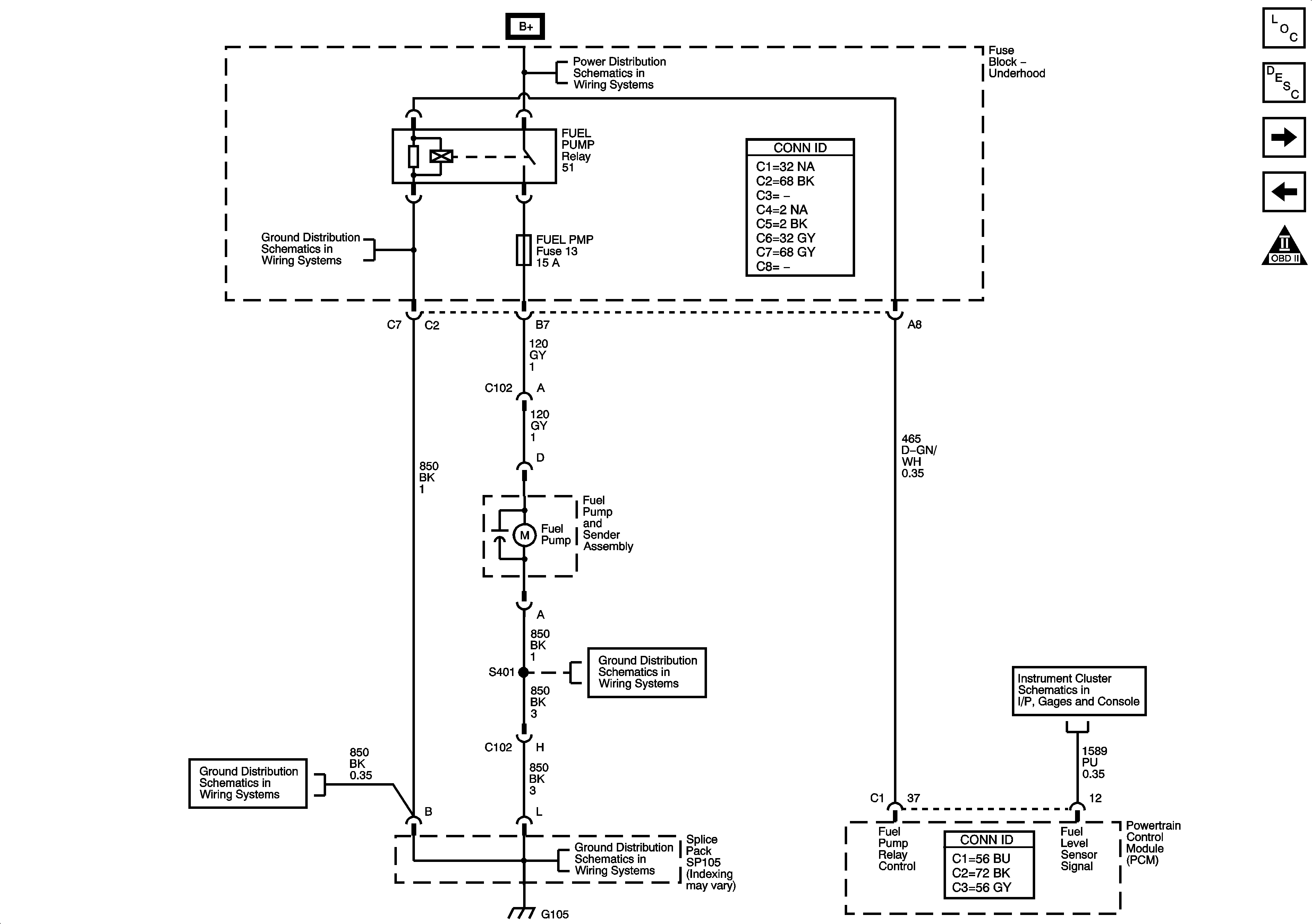
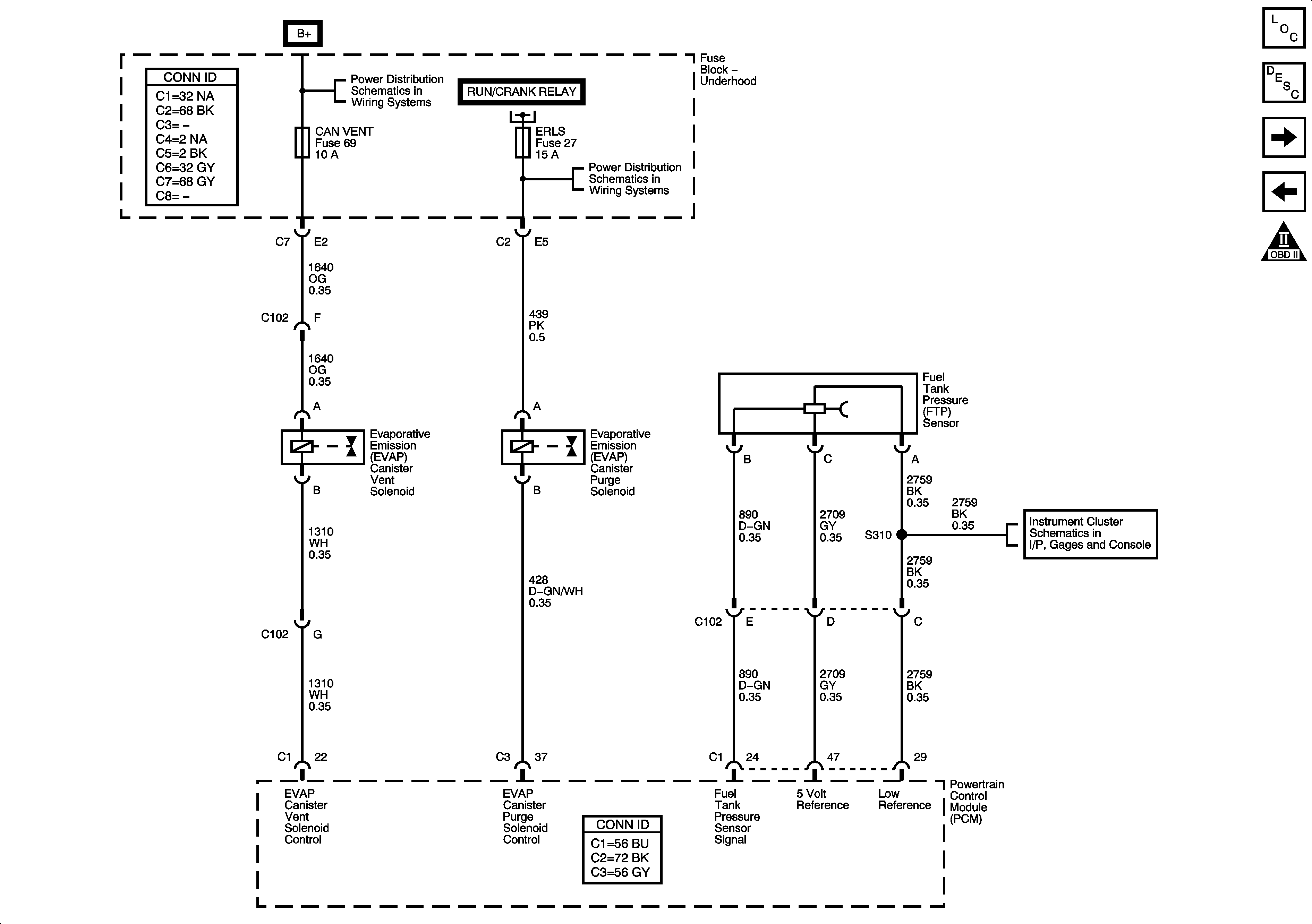
Figure 9:

Fuel and EVAP Controls


Object Number: 1284789  Size: FS
Master Electrical Component List
Powertrain Control Module Description
Controlled/Monitored Subsystem and Transmission References
Fuel Injection Controls
OBD II Symbol Description Notice
B+ Bus - Underhood Fuse Block
Power, Ground, MIL, and DLC
04 GMT355 Power Distribution Schematics - ERLS, FRT AXLE, PCM - I, and INJECTORS Fuses
Gages
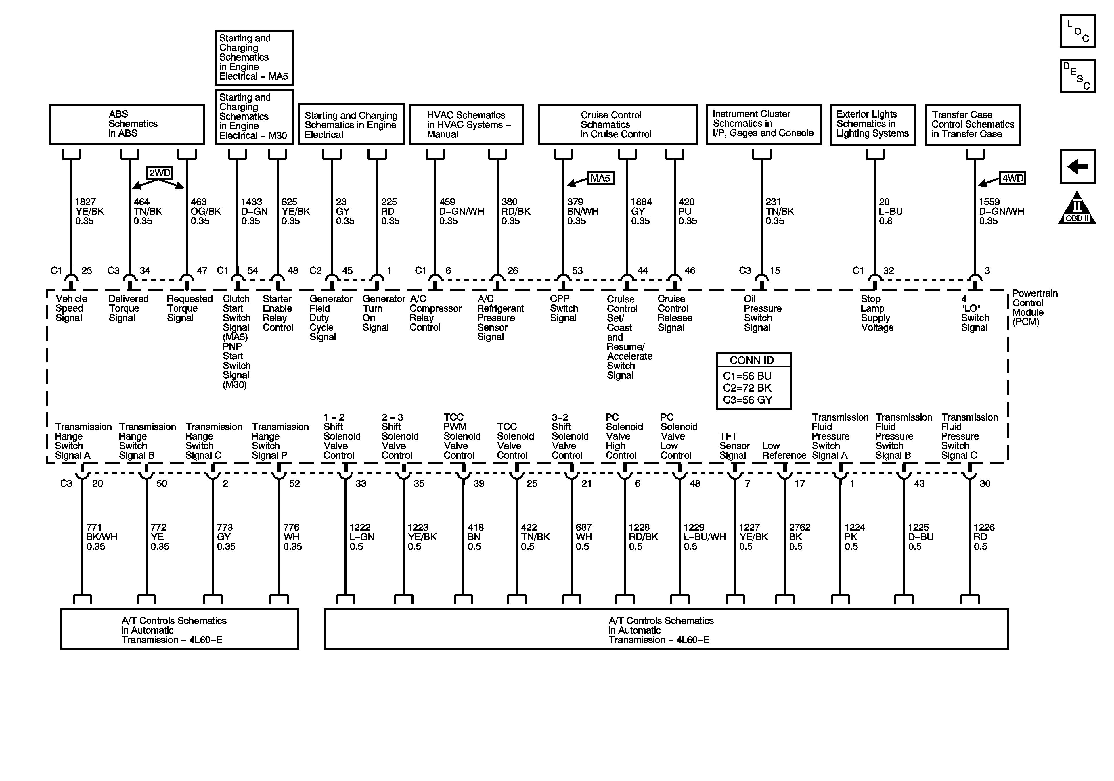
Figure 10:

Controlled/Monitored Subsystem and Transmission References


Object Number: 1284792  Size: FS
Master Electrical Component List
Powertrain Control Module Description
Fuel and EVAP Controls
OBD II Symbol Description Notice
Power, Ground, and Electronic Brake Control Module
Starting System (M30)
Starting System (MA5)
Charging System
Compressor Controls (C60)
Cruise Control
Indicators
Stop Lamps, and License Lamps
Transfer Case Encoder Motor
Switches and VSS
Transmission Controls