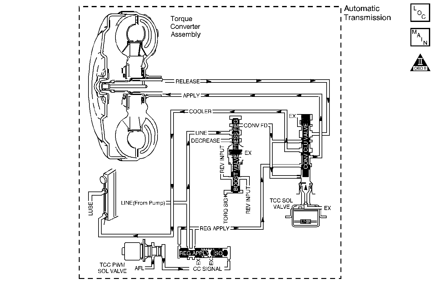
Circuit Description
The torque converter clutch (TCC) solenoid valve is a normally-open exhaust valve that is used with the torque converter clutch pulse width modulation (TCC PWM) solenoid in order to control fluid acting on the converter clutch apply valve. The TCC solenoid valve attaches to the transmission case assembly extending into the pump cover. When grounded, energized, by the powertrain control module (PCM), the TCC solenoid valve stops converter signal oil from exhausting. This causes converter signal oil pressure to increase and move the converter clutch apply valve against spring force and into the apply position. In this position, release fluid is open to an exhaust port and converter feed fluid fills the apply circuit. The converter feed fluid applies the TCC. When the PCM no longer provides a ground path, the TCC solenoid valve de-energizes and apply fluid exhausts, releasing the TCC.
When the PCM detects a high TCC slip speed when the PCM commands the TCC ON, then DTC P0741 sets. DTC P0741 is a type B DTC.
DTC Descriptor
This diagnostic procedure supports the following DTC:
DTC P0741 Torque Converter Clutch (TCC) System - Stuck Off
Conditions for Running the DTC
| • | No vehicle speed sensor (VSS) DTCs P0502 or P0503. |
| • | No TCC solenoid valve DTC P2769 or P2770. |
| • | No TCC DTC P0742. |
| • | Transmission fluid temperature (TFT) 20-150°C (68-300°F). |
| • | No transmission fluid pressure (TFP) manual valve position switch DTC P1810, P1815 or P1816. |
| • | The throttle position (TP) angle is 10-99 percent. |
| • | The engine speed is greater than 475 RPM for 5 seconds. |
| • | The gear ratio is 0.95-1.05 or 1.45-1.50. |
| • | The gear range is D2 or D3. |
| • | The TCC is commanded ON for 3 seconds. |
| • | The TCC duty cycle is 60 percent or greater. |
| • | Engine torque is 55-525 N·m (40-387 lb ft). |
Conditions for Setting the DTC
The TCC slip speed is 140 RPM or greater for 4 seconds. These conditions must occur 4 times.
Action Taken When the DTC Sets
| • | The PCM illuminates the malfunction indicator lamp (MIL) during the second consecutive trip in which the Conditions for Setting the DTC are met. |
| • | The PCM commands maximum line pressure. |
| • | The PCM commands TCC OFF. |
| • | The PCM inhibits fourth gear if TFT is greater than 100°C (212°F). |
| • | The PCM freezes transmission adapt functions. |
| • | The PCM records the operating conditions when the Conditions for Setting the DTC are met. The PCM stores this information as Freeze Frame and Failure Records. |
| • | The PCM stores DTC P0741 in PCM history during the second consecutive trip in which the Conditions for Setting the DTC are met. |
Conditions for Clearing the MIL/DTC
| • | The PCM turns OFF the MIL during the third consecutive trip in which the diagnostic test runs and passes. |
| • | A scan tool can clear the MIL/DTC. |
| • | The PCM clears the DTC from PCM history if the vehicle completes 40 warm-up cycles without an emission-related diagnostic fault occurring. |
| • | The PCM cancels the DTC default actions when the fault no longer exists and/or the ignition switch is OFF long enough in order to power down the PCM. |
Diagnostic Aids
| • | DTC P0741 Code will not pass and will always show Code not passed since code clear. |
| • | Contamination may cause the TCC apply valve to stick in the valve body. |
| • | There may be internal damage in the torque converter causing the no TCC apply. |
Test Description
The numbers below refer to the step numbers on the diagnostic table.
-
This step inspects for excessive TCC slip when the TCC is commanded ON.
-
This step inspects for possible causes of no TCC apply.
Step | Action | Values | Yes | No | ||||||||||
|---|---|---|---|---|---|---|---|---|---|---|---|---|---|---|
1 | Did you perform the Diagnostic System Check - Vehicle? | -- | Go to Step 2 | Go to Diagnostic System Check - Vehicle in Vehicle DTC Information | ||||||||||
Important: Before clearing the DTC, use the scan tool in order to record the Freeze Frame and Failure Records. Using the Clear Info function erases the Freeze Frame and Failure Records from the PCM. While the scan tool TCC Enable is Yes, does the scan tool display a TCC Slip Speed greater than the specified range? | 130 RPM | Go to Step 3 | Go to Testing for Intermittent Conditions and Poor Connections in Wiring Systems | |||||||||||
The TCC is hydraulically or mechanically stuck OFF. Inspect for the following conditions:
Refer to Symptoms - Automatic Transmission NO TCC apply. Was the condition found? | -- | Go to Step 4 | -- | |||||||||||
4 | Perform the following procedure in order to verify the repair:
Hold the throttle at 20-99 percent and accelerate to 88 km/h (55 mph). Ensure that the TCC is commanded ON and the TCC Slip Speed is less than 50 RPM for 2 seconds. Has the test run and passed? | -- | Go to Step 5 | Go to Step 2 | ||||||||||
5 | With the scan tool, observe the stored information, capture info, and DTC Info. Does the scan tool display any DTCs that you have not diagnosed? | -- | Go to Diagnostic Trouble Code (DTC) List - Vehicle in Vehicle DTC Information | System OK |
