| Subject: | Revised Crossmember Replacement Procedure |
| Models: | 2004-2005 Chevrolet Colorado |
This bulletin is being issued to revise the Crossmember Replacement procedure in the Frame and Underbody sub-section of the Service Manual. Please replace the current information in the Service Manual with the following information.
The following information has been updated within SI. If you are using a paper version of this Service Manual, please make a reference to this bulletin on the affected page.
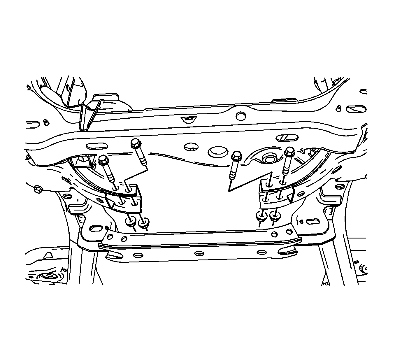
Model year 2004 and early 2005 (prior to April, 2005) vehicles had the front crossmember-to-frame bolts installed front-to-rear. This made crossmember removal more time-consuming because it was necessary to rotate the steering gear out of the way. We now
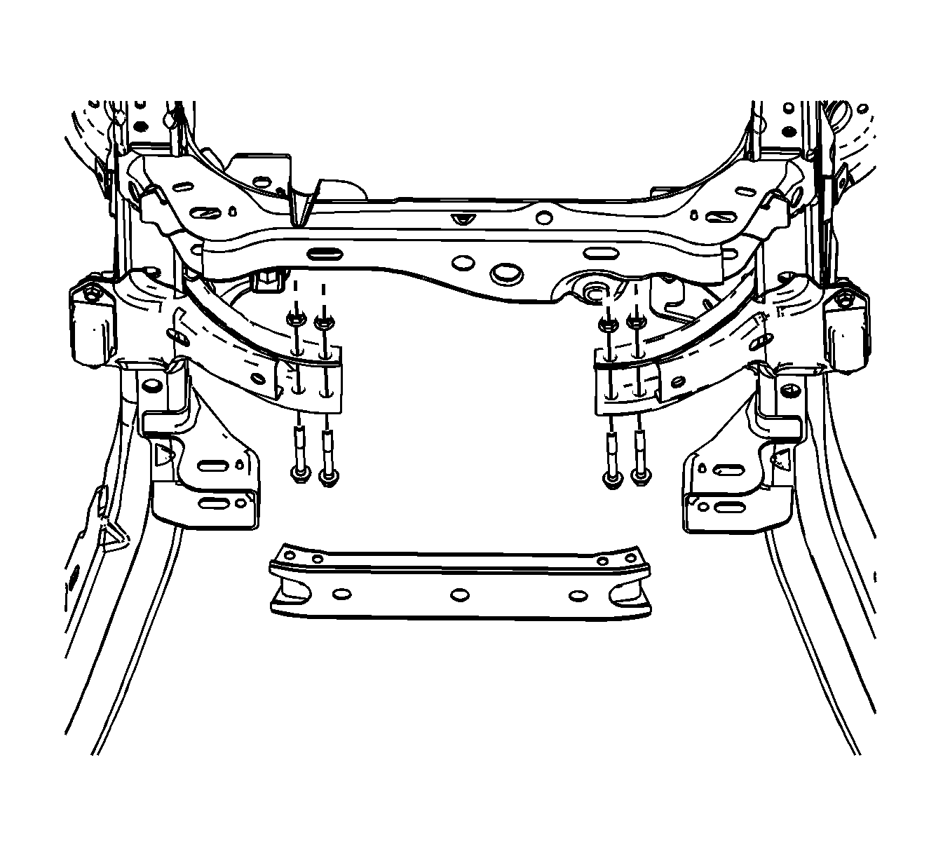
recommend that when the front crossmember-to-frame bolts are reinstalled that they be reversed so that if crossmember removal is necessary in the future, the steering gear will not have to be rotated. The assembly plant began installing the bolts rear-to-front
beginning in April 2005.
Crossmember Replacement (Early Design) [Prior to April 2005]
Removal Procedure
- Raise the vehicle. Refer to Lifting and Jacking the Vehicle in General Information.
- Remove the coupler clamp bolt from the intermediate shaft. Refer to Intermediate Steering Shaft Replacement - Lower in Steering Wheel and Column.
- Separate the intermediate shaft from the steering gear.

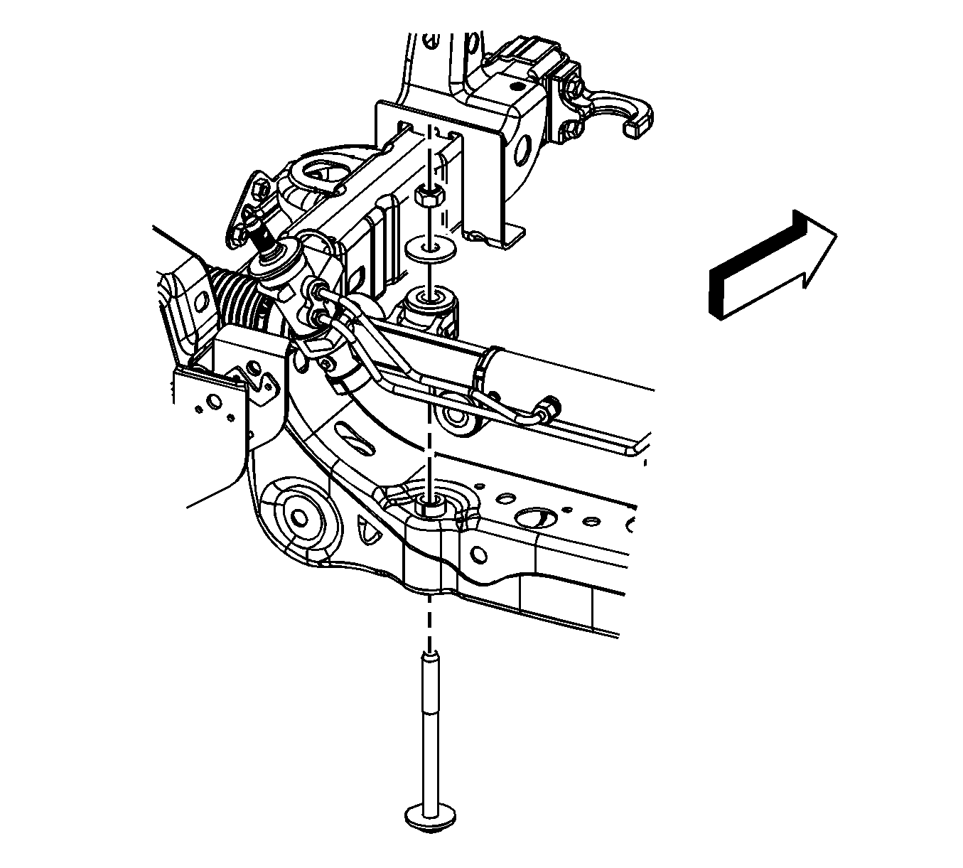
- Remove the long vertical steering gear mounting bolt.

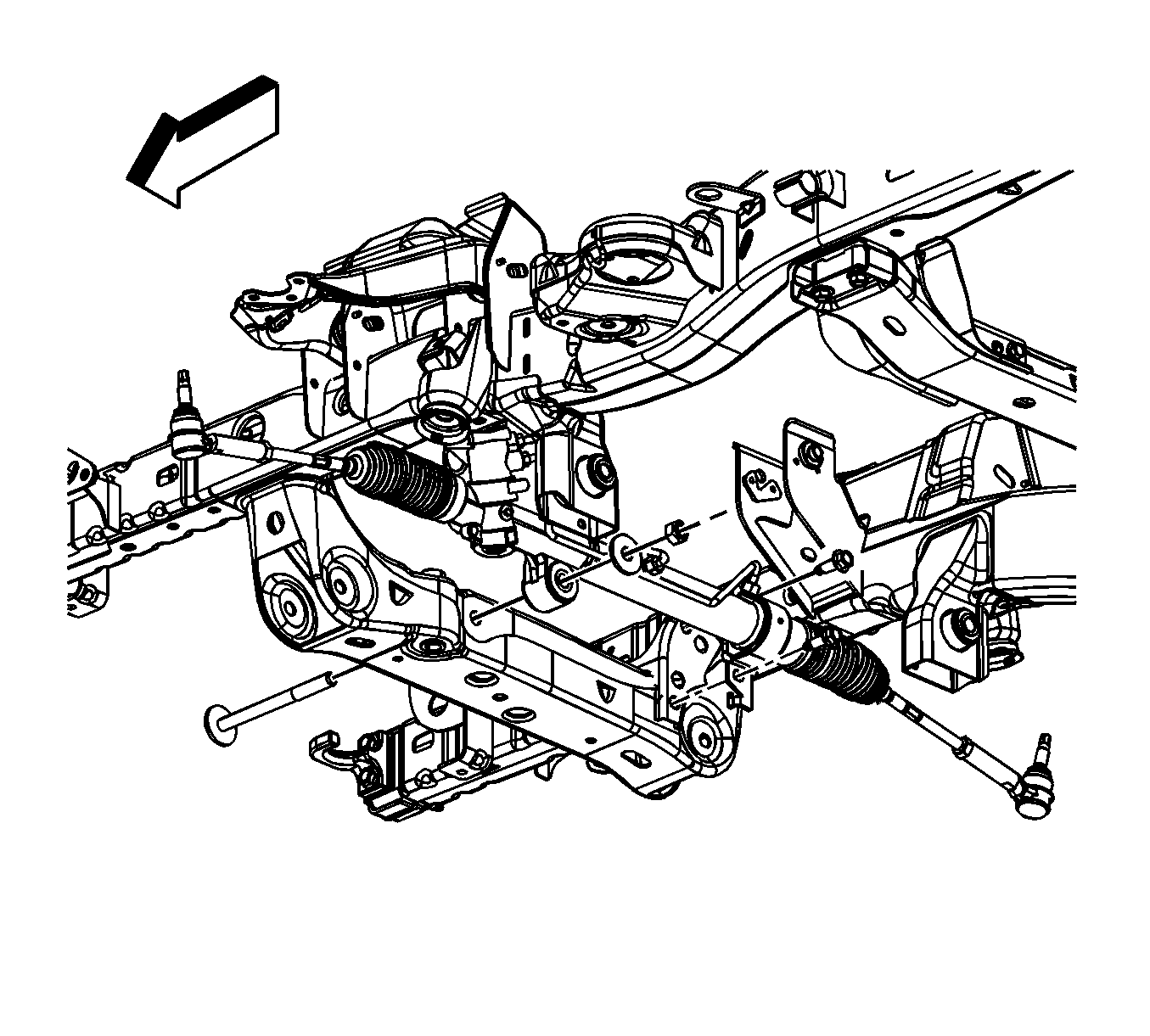
- Remove the 2 short horizontal isolator clamp bolts.
- Loosen the long horizontal steering gear mounting bolt.
- Tilt the steering gear to allow access to the frame crossmember bolts.

- Remove the crossmember mounting nuts and bolts .
- Remove the crossmember from the vehicle.
Installation Procedure

- Install the crossmember to the vehicle.
- Reverse the orientation of the crossmember bolts then reinstall them.
- Perform the following procedure before installing the bolts:
| • | Remove all traces of the original adhesive patch. |
| • | Clean the threads of the bolt with denatured alcohol or equivalent and allow to dry. |
| • | Apply Threadlocker GM P/N 12345493 (Canadian P/N 10953488). |
Notice: Refer to Fastener Notice in Cautions and Notices.
- Install the bolts and the nuts.
Tighten
Tighten the bolts to 60 N·m (44 lb ft).

- Install the 2 short horizontal isolator clamp bolts. Do not tighten.
- Install the long vertical mounting bolt, washer, and nut to the power steering gear. Do not tighten.

- Install the long vertical mounting bolt, washer, and nut to the power steering gear.
Tighten
| • | Tighten the mounting bolt nuts to 130 N·m (96 lb ft). |
| • | Tighten the isolator clamp bolts to 100 N·m (74 lb ft). |
- Connect the intermediate shaft to the steering gear.
- Install the coupler clamp bolt to the intermediate shaft. Refer to Intermediate Steering Shaft Replacement - Lower in Steering Wheel and Column.
- Lower the vehicle.
Crossmember Replacement (Late Design) [April 2005 and Later]
Removal Procedure
- Raise the vehicle. Refer to Lifting and Jacking the Vehicle in General Information.

- Remove the crossmember mounting nuts and bolts .
- Remove the crossmember from the vehicle.
Installation Procedure

- Install the crossmember to the vehicle.
- Perform the following procedure before installing the bolts.
| • | Remove all traces of the original adhesive patch. |
| • | Clean the threads of the bolt with denatured alcohol or equivalent and allow to dry. |
| • | Apply Threadlocker GM P/N 12345493 (Canadian P/N 10953488). |
Notice: Refer to Fastener Notice in Cautions and Notices.
- Install the bolts and the nuts.
Tighten
Tighten the bolts to 60 N·m (44 lb ft).
- Lower the vehicle.


