Removal Procedure
- Remove the intake manifold. Refer to
Intake Manifold Replacement
.
- Remove the ignition coils. Refer to
Ignition Coil Replacement
in Engine Controls-3.5L (L52).

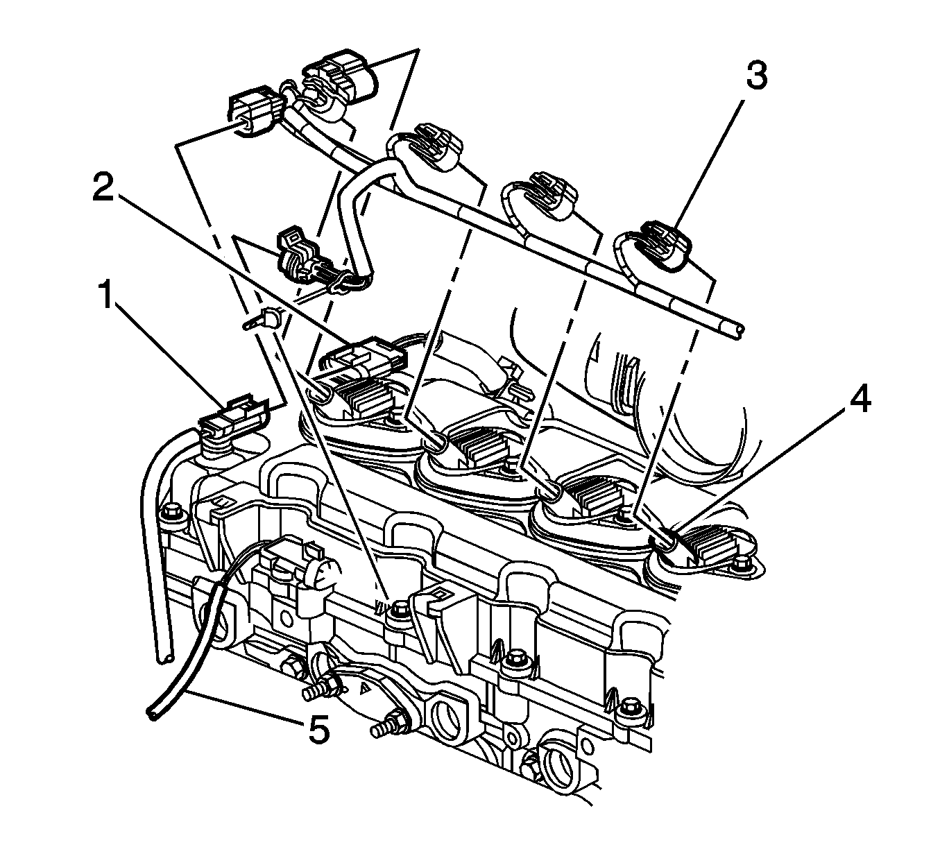
- Disconnect the following electrical connectors from the camshaft cover.
| • | The engine coolant temperature (ECT) sensor (1) |
| • | The heated oxygen sensor (HO2S) (5) |
- Remove the fuel pressure regulator screw, in order to gain clearance to
remove the camshaft cover.

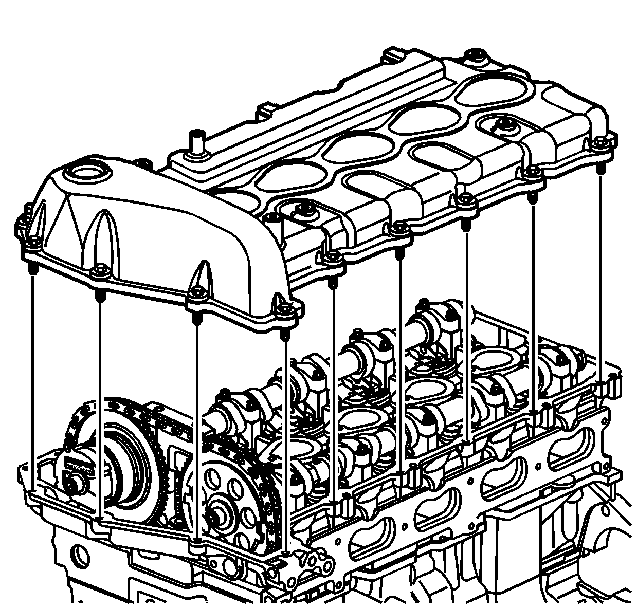
- Remove the camshaft cover bolts.
- Remove the camshaft cover from the cylinder head.
- Remove the seals from the camshaft cover.
Do not reuse the seals.
- Clean and inspect the cylinder head sealing surface.
- Clean and inspect the camshaft cover. Refer to
Camshaft Cover Cleaning and Inspection
.
Installation Procedure
- Install a NEW camshaft cover seal into the camshaft cover groove.
- Install NEW ignition control module seals into the camshaft cover grooves.

- Position the camshaft cover to the cylinder
head.
Notice: Refer to Fastener Notice in the Preface section.
- Install the camshaft cover bolts.
Tighten
Tighten the camshaft cover bolts to 10 N·m (89 lb in).
- Install the fuel pressure regulator screw.
Tighten
Tighten the fuel pressure regulator screw to 8 N·m (71 lb in).

- Connect the following electrical connectors to the camshaft cover.
- Install the ignition coils. Refer to
Ignition Coil Replacement
in Engine Controls-3.5L (L52).
- Install the intake manifold. Refer to
Intake Manifold Replacement
.


