Transmission Replacement RWD
Tools Required
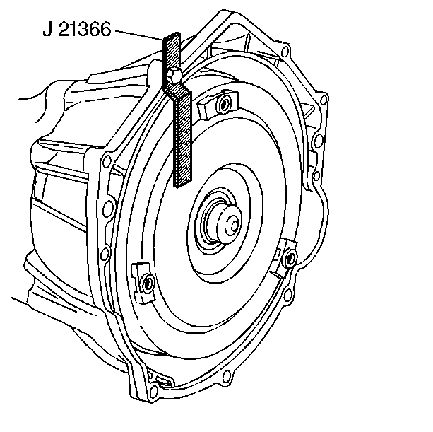
J 21366 Converter Holding Strap
Removal Procedure
- Ensure the vehicle is in the PARK position.
- Remove the filler tube. Refer to Transmission Fluid Filler Tube and Seal Replacement .
- Drain the transmission fluid if necessary. Refer to Automatic Transmission Fluid and Filter Replacement .
- Remove the rear propeller shaft. Refer to One-Piece Propeller Shaft Replacement or Two-Piece Propeller Shaft Replacement
- Complete the following in order to disconnect the range selector cable (3) from the transmission range selector lever ball stud.
- Remove the retainer (4) from the range selector cable (3).
- Push the range selector cable locking tabs inward toward each other to release from the bracket (2).
- Disconnect the following engine wiring harness electrical connectors:
- Remove the screw (4) securing the engine wiring harness (3) to the right side of the transmission, and position the harness over the transmission.
- Disconnect the park/neutral back up switch electrical connector (3).
- Remove the screw (2) securing the engine wiring harness (1) to the left side of the transmission, and position the wiring harness aside.
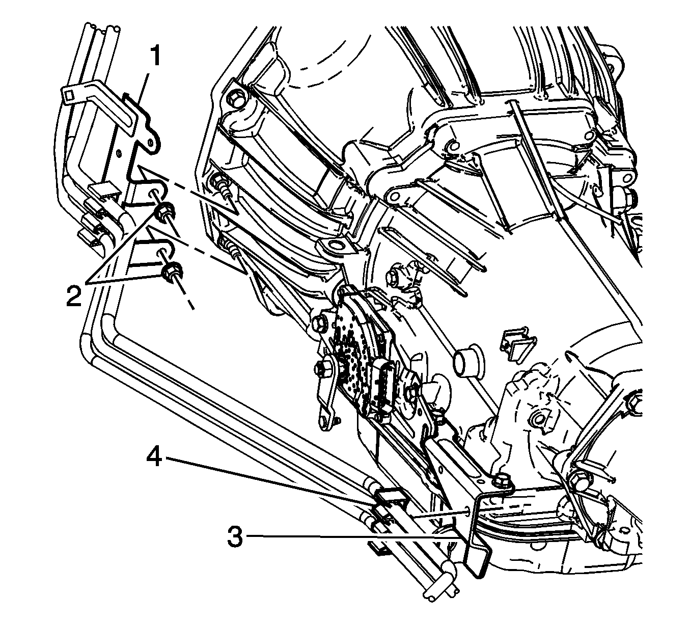
- Disconnect the transmission vent hose retainer (1) from the heater pipe bracket (2).
- Remove the nuts (2) securing the fuel hose/pipe bracket (1) to the transmission.
- Disconnect the fuel hose/pipe retainer (4) from the range selector cable bracket (3), and position aside the fuel hose/pipe bundle.
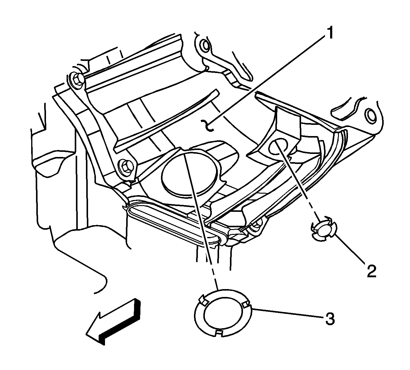
- Remove the inspection plug (3) from the transmission (1).
- Mark the torque converter to flexplate/flywheel orientation to ensure proper realignment.
- Remove the engine protection shield in order to access the harmonic balancer bolt. Refer to Engine Protection Shield Replacement .
- Remove the service slot plug.
- Repeat the following steps for all 3 torque converter bolts:
- Place an oil pan under the transmission fluid cooler pipes.
- Disconnect the transmission oil cooler pipes from the transmission ONLY. Refer to Transmission Fluid Cooler Hose/Pipe Replacement .
- Plug the open outlet ports to prevent fluid loss and contamination.
- Support and secure the transmission using a suitable transmission jack.
- Remove the transmission crossmember. Refer to Transmission Support Crossmember Replacement .
- Remove the 9 transmission mounting bolts.
- Remove the remaining transmission mounting bolts (2).
- Using the transmission jack, carefully lower the transmission from the vehicle.
- Install the J 21366 onto the transmission bell housing to retain the torque converter.
- Perform the flush and flow test on the automatic transmission oil cooler. Refer to Transmission Fluid Cooler Flushing and Flow Test .
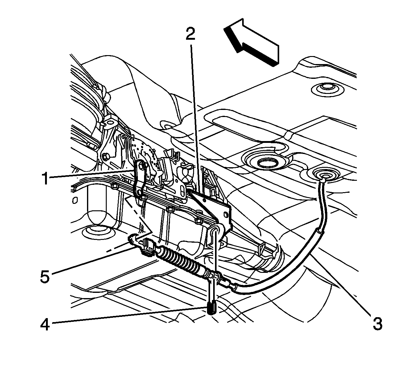
Important: Do not pull on the boot portion of the cable.
| 5.1. | Insert a flat-bladed tool between the range selector cable end (5) and the range selector lever (1). |
| 5.2. | Pry the range selector cable end (5) away from the range selector lever (1). |
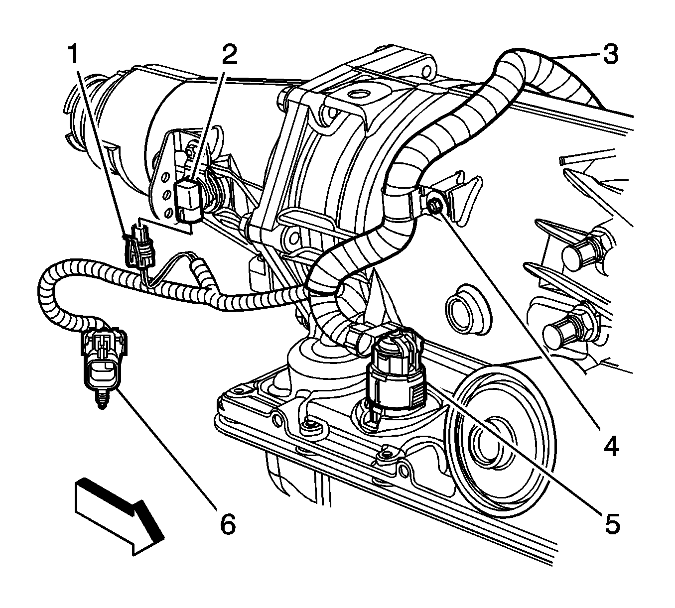
| • | The heated oxygen sensor (6) |
| • | The transmission main connector (5) |
| • | The vehicle speed sensor (VSS) (1) |
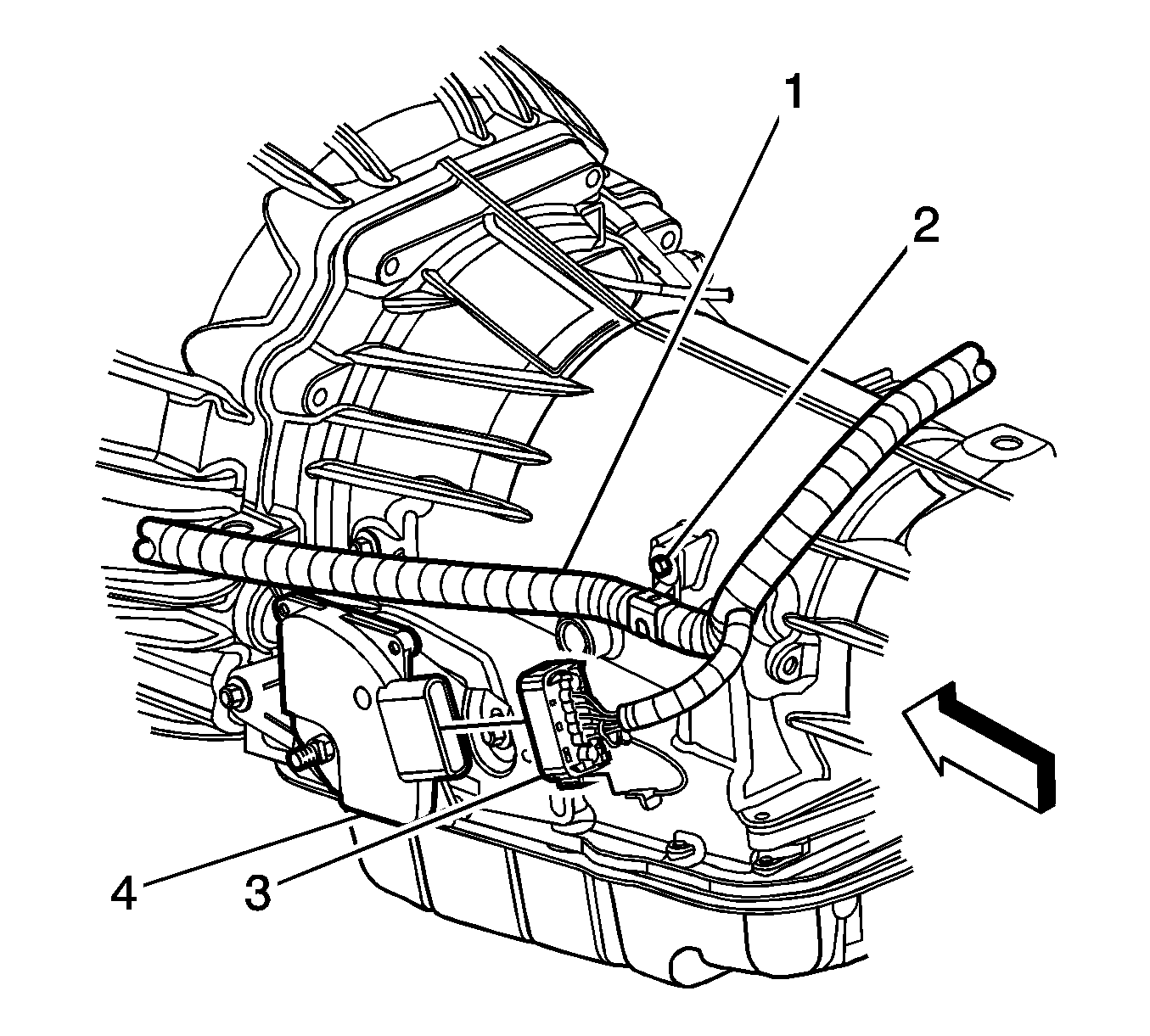
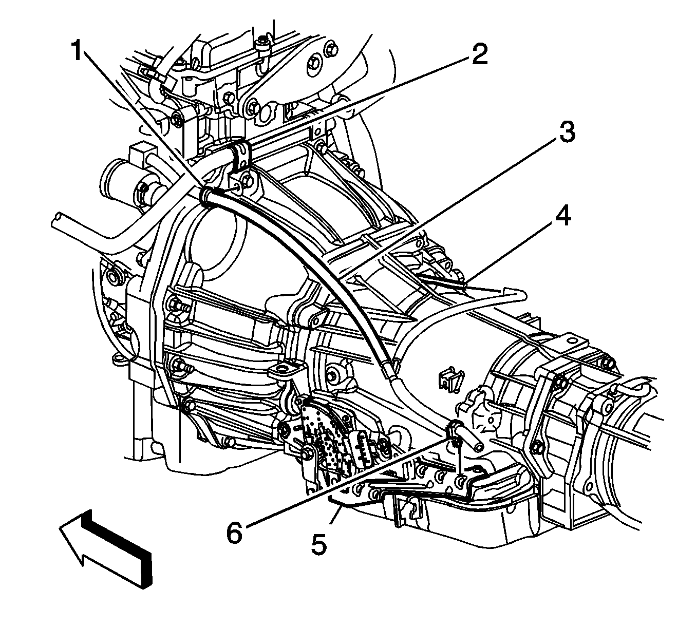
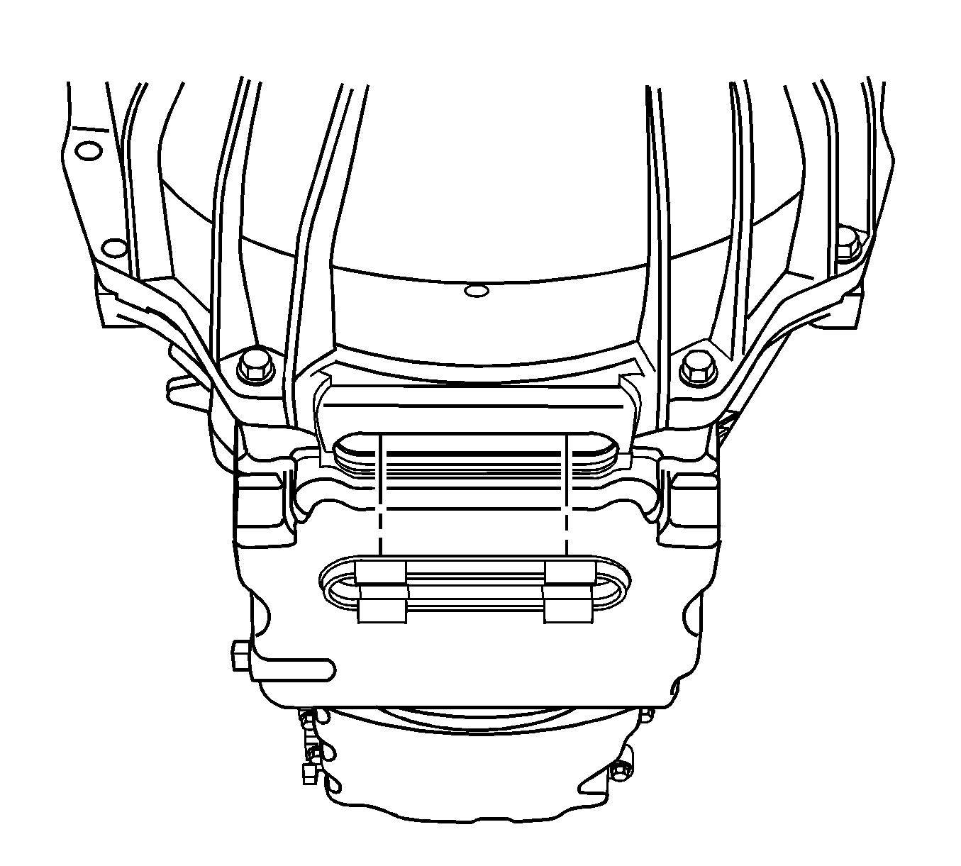
| 19.1. | Rotate the harmonic balancer center bolt clockwise ONLY, in order to access the torque converter bolt through the service slot. |
| 19.2. | Remove the torque converter bolt using one of the following: |
| - | 18 mm crowfoot wrench |
| - | Short T50 TORX bit |
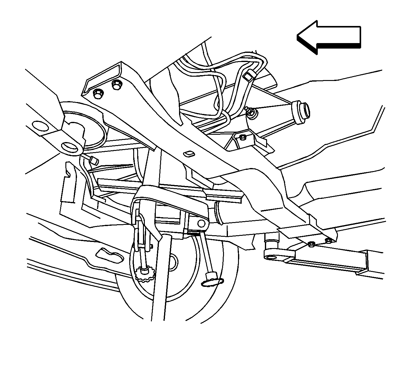
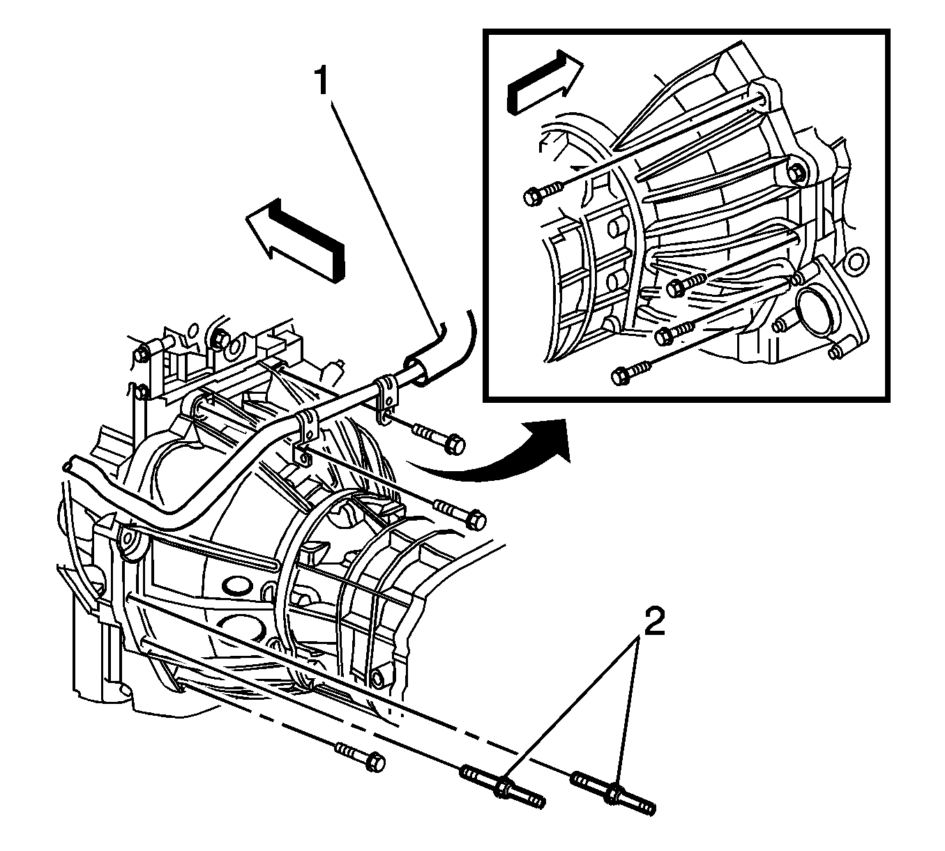
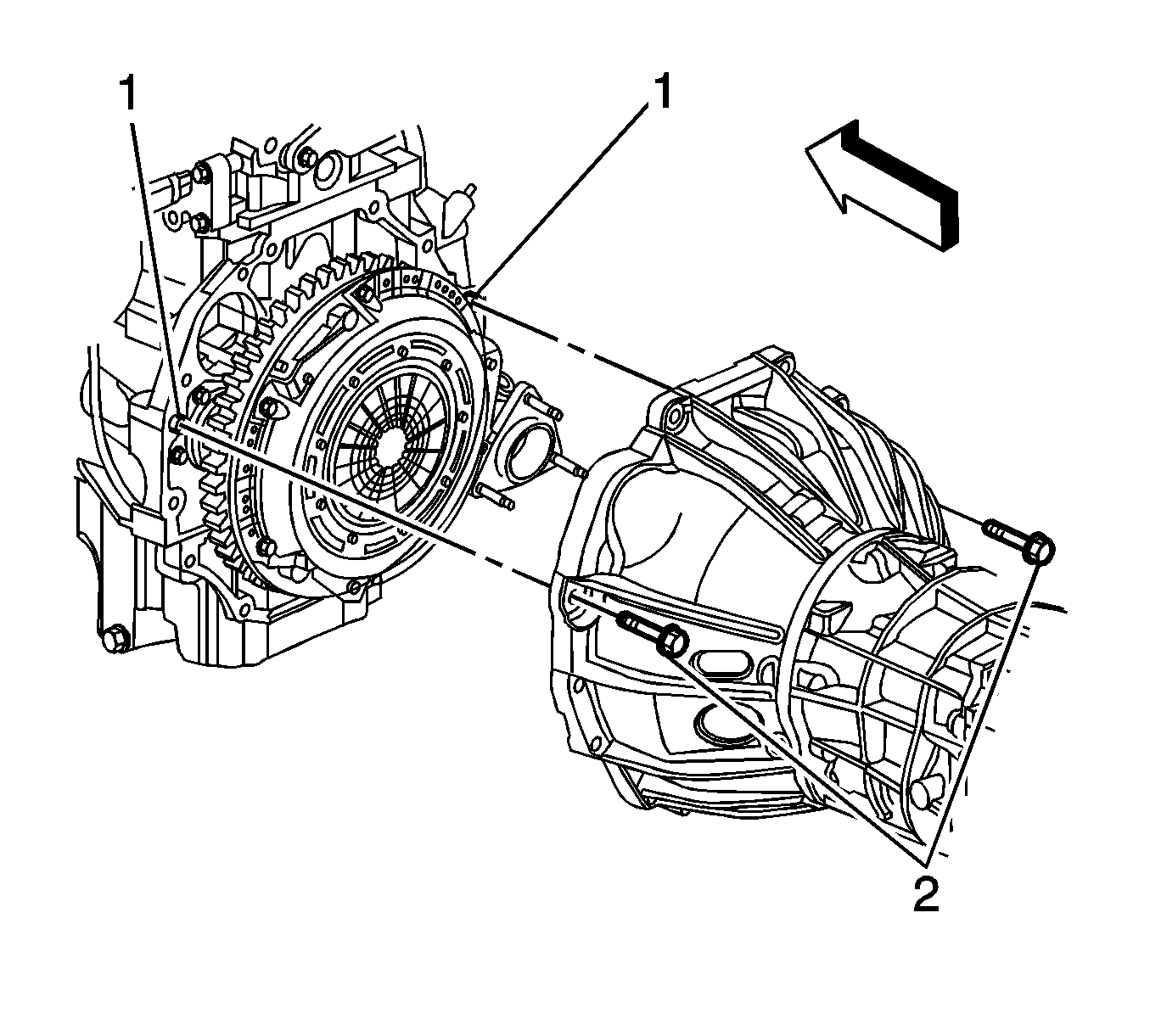

Important: Ensure clearance is maintained between the transmission and the following:
• The catalytic converter • The engine wiring harness • The fuel hose/pipe brackets • The heater pipe • The transmission oil cooler pipes
Installation Procedure
- Remove the J 21366 from the transmission.
- Ensure the torque converter is fully engaged with the transmission oil pump.
- Using the transmission jack, carefully raise the transmission to the engine.
- Align the transmission with the engine dowels (1).
- Install the 2 transmission mounting bolts (2).
- Install the remaining transmission mounting bolts.
- Install the transmission crossmember. Refer to Transmission Support Crossmember Replacement .
- Remove the transmission jack from under the vehicle.
- Connect the transmission oil cooler pipes to the transmission. Refer to Transmission Fluid Cooler Hose/Pipe Replacement .
- Align the torque converter to flexplate/flywheel orientation marks made during the removal procedure.
- Repeat the following steps for all 3 torque converter bolts:
- Install the inspection plug (3) to the transmission (1).
- Install the service slot plug.
- Install the nuts (2) securing the fuel hose/pipe bracket (1) to the transmission.
- Connect the fuel hose/pipe retainer (4) to the range selector cable bracket (3).
- Connect the transmission vent hose retainer (1) to the heater pipe bracket (2).
- Install the screw (1) securing the engine wiring harness (2) to the left side of the transmission.
- Connect the park/neutral back up switch electrical connector (3).
- Lay the engine wiring harness over the transmission.
- Connect the following engine wiring harness electrical connectors:
- Install the screw (4) securing the engine wiring harness (3) to the right side of the transmission.
- Install the range selector cable (3) to the bracket (2).
- Install the retainer (4) to the range selector cable (3).
- Adjust the automatic transmission range selector cable. Refer to Range Selector Lever Cable Adjustment .
- Install the rear propeller shaft. Refer to One-Piece Propeller Shaft Replacement or Two-Piece Propeller Shaft Replacement .
- Install the engine protection shield. Refer to Engine Protection Shield Replacement .
- Install the filler tube. Refer to Transmission Fluid Filler Tube and Seal Replacement .
- Fill the transmission fluid if necessary. Refer to Automatic Transmission Fluid and Filter Replacement .
- Lower the vehicle.


Important: Ensure clearance is maintained between the transmission and the following:
• The catalytic converter • The engine wiring harness • The fuel hose/pipe brackets • The heater pipe • The transmission oil cooler pipes

Notice: Refer to Fastener Notice in the Preface section.
Important: Ensure the torque converter turns freely while tightening the transmission mounting bolts.
Tighten
Tighten the transmission mounting bolts to 50 N·m (37 lb ft).

Important:
• Ensure the studded mounting bolts (2) are located in the correct position. • The heater pipe (1) must be secured with the 2 upper mounting bolts.
Tighten
Tighten the transmission mounting bolts to 50 N·m (37 lb ft).
| 11.1. | Rotate the harmonic balancer center bolt clockwise ONLY, in order to access the torque converter bolt holes in the flexplate/flywheel through the service slot. |
| 11.2. | To aid in alignment of the torque converter to the flexplate/flywheel. Install all 3 torque converter bolts before fully tightening using one of the following: |
Tighten
Tighten the torque converter bolts to 60 N·m (44 lb ft).
| - | 18 mm crowfoot wrench |
| - | Short T50 TORX bit |


Tighten
Tighten the fuel hose/pipe bracket nuts to 20 N·m (15 lb ft).


Tighten
Tighten the engine wiring harness retainer to transmission screw to 9 N·m (80 lb in).

| • | The heated oxygen sensor (6) |
| • | The transmission main connector (5) |
| • | The vehicle speed sensor (VSS) (1) |
Tighten
Tighten the engine wiring harness retainer to transmission screw to 9 N·m (80 lb in).

Transmission Final Test and Inspection
Complete the following procedure after the transmission is installed in the vehicle:
- With the ignition OFF or disconnected, crank the engine several times. Listen for any unusual noises or evidence that any parts are binding.
- Place transmission in neutral, start the engine and listen for any unusual noises or evidence that any parts are binding.
- While the engine continues to idle raise and support the vehicle. Refer to Lifting and Jacking the Vehicle .
- Perform a final inspection for the proper fluid level. Refer to Transmission Fluid Check .
- Lower the vehicle.
- Reset the TAP values. Refer to Transmission Adaptive Functions .
- Road test the vehicle.
Important: It is recommended that transmission adaptive pressure (TAP) information be reset.
Resetting the TAP values using a scan tool will erase all learned values in all cells. As a result, The ECM, PCM or TCM will need to relearn TAP values. Transmission performance may be affected as new TAP values are learned.Transmission Replacement 4WD
Tools Required
J 21366 Converter Holding Strap
Removal Procedure
- Ensure the vehicle is in the PARK position.
- Remove the filler tube. Refer to Transmission Fluid Filler Tube and Seal Replacement .
- Drain the transmission fluid if necessary. Refer to Automatic Transmission Fluid and Filter Replacement .
- Remove the transfer case assembly. Refer to Transfer Case Assembly Replacement .
- Complete the following in order to disconnect the range selector cable (3) from the transmission range selector lever ball stud.
- Remove the retainer (4) from the range selector cable (3).
- Push the range selector cable locking tabs inward toward each other to release from the bracket (2).
- Disconnect the transmission main electrical connector (3).
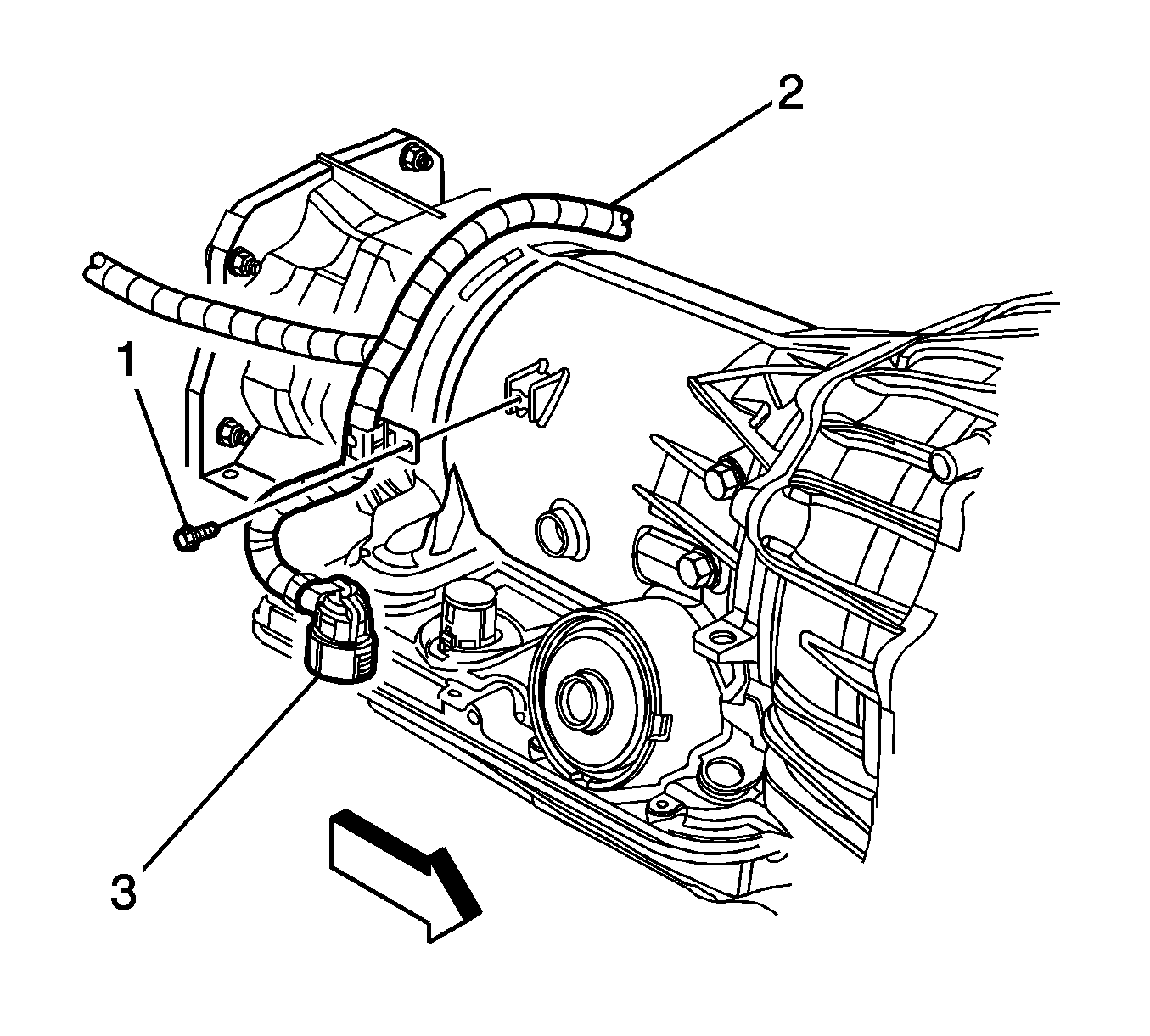
- Remove the screw (1) securing the engine wiring harness (2) to the right side of the transmission, and position the harness over the transmission.
- Disconnect the park/neutral back up switch electrical connector (3).
- Remove the screw (2) securing the engine wiring harness (1) to the left side of the transmission, and position the wiring harness aside.
- Disconnect the transmission vent hose retainer (1) from the heater pipe bracket (2).
- Remove the nuts (2) securing the fuel hose/pipe bracket (1) to the transmission.
- Disconnect the fuel hose/pipe retainer (4) from the range selector cable bracket (3), and position aside the fuel hose/pipe bundle.
- Remove the inspection plug (3) from the transmission (1).
- Mark the torque converter to flexplate/flywheel orientation to ensure proper realignment.
- Remove the engine protection shield in order to access the harmonic balancer bolt. Refer to Engine Protection Shield Replacement .
- Remove the service slot plug.
- Repeat the following steps for all 3 torque converter bolts:
- Place an oil pan under the transmission fluid cooler pipes.
- Disconnect the transmission oil cooler pipes from the transmission ONLY. Refer to Transmission Fluid Cooler Hose/Pipe Replacement .
- Plug the open outlet ports to prevent fluid loss and contamination.
- Support and secure the transmission using a suitable transmission jack.
- Remove the transmission crossmember. Refer to Transmission Support Crossmember Replacement .
- Remove the 9 transmission mounting bolts.
- Remove the remaining transmission mounting bolts (2).
- Using the transmission jack, carefully lower the transmission from the vehicle.
- Install the J 21366 onto the transmission bell housing to retain the torque converter.
- Perform the flush and flow test on the automatic transmission oil cooler. Refer to Transmission Fluid Cooler Flushing and Flow Test .

Important: Do not pull on the boot portion of the cable.
| 5.1. | Insert a flat-bladed tool between the range selector cable end (5) and the range selector lever (1). |
| 5.2. | Pry the range selector cable end (5) away from the range selector lever (1). |


| 19.1. | Rotate the harmonic balancer center bolt clockwise ONLY, in order to access the torque converter bolt through the service slot. |
| 19.2. | Remove the torque converter bolt using one of the following: |
| - | 18 mm crowfoot wrench |
| - | Short T50 TORX bit |


Important: Ensure clearance is maintained between the transmission and the following:
• The catalytic converter • The engine wiring harness • The fuel hose/pipe brackets • The heater pipe • The transmission oil cooler pipes

Installation Procedure
- Remove the J 21366 from the transmission.
- Ensure the torque converter is fully engaged with the transmission oil pump.
- Using the transmission jack, carefully raise the transmission to the engine.
- Align the transmission with the engine dowels (1).
- Install the 2 transmission mounting bolts (2).
- Install the remaining transmission mounting bolts.
- Install the transmission crossmember. Refer to Transmission Support Crossmember Replacement .
- Remove the transmission jack from under the vehicle.
- Connect the transmission oil cooler pipes to the transmission. Refer to Transmission Fluid Cooler Hose/Pipe Replacement .
- Align the torque converter to flexplate/flywheel orientation marks made during the removal procedure.
- Repeat the following steps for all 3 torque converter bolts:
- Install the inspection plug (3) to the transmission (1).
- Install the service slot plug.
- Install the nuts (2) securing the fuel hose/pipe bracket (1) to the transmission.
- Connect the fuel hose/pipe retainer (4) to the range selector cable bracket (3).
- Connect the transmission vent hose retainer (1) to the heater pipe bracket (2).
- Install the screw (1) securing the engine wiring harness (2) to the left side of the transmission.
- Connect the park/neutral back up switch electrical connector (3).
- Lay the engine wiring harness over the transmission.
- Connect the transmission main electrical connector (3).
- Install the screw (1) securing the engine wiring harness (2) to the right side of the transmission.
- Install the range selector cable (3) to the bracket (2).
- Install the retainer (4) to the range selector cable (3).
- Adjust the automatic transmission range selector cable. Refer to Range Selector Lever Cable Adjustment .
- Install the transfer case assembly. Refer to Transfer Case Assembly Replacement .
- Install the engine protection shield. Refer to Engine Protection Shield Replacement .
- Install the filler tube. Refer to Transmission Fluid Filler Tube and Seal Replacement .
- Fill the transmission fluid if necessary. Refer to Automatic Transmission Fluid and Filter Replacement .
- Lower the vehicle.


Important: Ensure clearance is maintained between the transmission and the following:
• The catalytic converter • The engine wiring harness • The fuel hose/pipe brackets • The heater pipe • The transmission oil cooler pipes

Notice: Refer to Fastener Notice in the Preface section.
Important: Ensure the torque converter turns freely while tightening the transmission mounting bolts.
Tighten
Tighten the transmission mounting bolts to 50 N·m (37 lb ft).

Important:
• Ensure the studded mounting bolts (2) are located in the correct position. • The heater pipe (1) must be secured with the 2 upper mounting bolts.
Tighten
Tighten the transmission mounting bolts to 50 N·m (37 lb ft).
| 11.1. | Rotate the harmonic balancer center bolt clockwise ONLY, in order to access the torque converter bolt holes in the flexplate/flywheel through the service slot. |
| 11.2. | To aid in alignment of the torque converter to the flexplate/flywheel. Install all 3 torque converter bolts before fully tightening using one of the following: |
Tighten
Tighten the torque converter bolts to 60 N·m (44 lb ft).
| - | 18 mm crowfoot wrench |
| - | Short T50 TORX bit |


Tighten
Tighten the fuel hose/pipe bracket nuts to 20 N·m (15 lb ft).


Tighten
Tighten the engine wiring harness retainer to transmission screw to 9 N·m (80 lb in).

Tighten
Tighten the engine wiring harness retainer to transmission screw to 9 N·m (80 lb in).

Transmission Final Test and Inspection
Complete the following procedure after the transmission is installed in the vehicle:
- With the ignition OFF or disconnected, crank the engine several times. Listen for any unusual noises or evidence that any parts are binding.
- Place transmission in neutral, start the engine and listen for any unusual noises or evidence that any parts are binding.
- While the engine continues to idle raise and support the vehicle. Refer to Lifting and Jacking the Vehicle .
- Perform a final inspection for the proper fluid level. Refer to Transmission Fluid Check .
- Lower the vehicle.
- Reset the TAP values. Refer to Transmission Adaptive Functions .
- Road test the vehicle.
Important: It is recommended that transmission adaptive pressure (TAP) information be reset.
Resetting the TAP values using a scan tool will erase all learned values in all cells. As a result, The ECM, PCM or TCM will need to relearn TAP values. Transmission performance may be affected as new TAP values are learned.