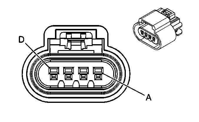
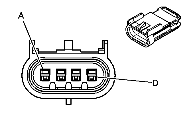
C100 Engine Harness to the Front Axle Jumper Harness (4WD)
|
|
Connector Part Information
| Connector Part Information
|
Terminal Part Information
| Terminal Part Information
|
Pin | Wire Color | Circuit No. | Function | Pin | Wire Color | Circuit No. | Function |
|---|---|---|---|---|---|---|---|
A | BK/WH | 1695 | Axle Switch Signal | A | BK/WH | 1695 | Axle Switch Signal |
B | L-BU | 1296 | Axle Actuator - Control | B | L-BU | 1296 | Axle Actuator - Control |
C | PK | 1539 | Ignition 1 Voltage | C | PK | 1539 | Ignition 1 Voltage |
D | BK | 550 | Ground | D | BK | 550 | Ground |
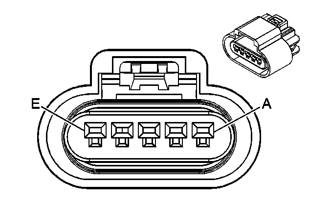
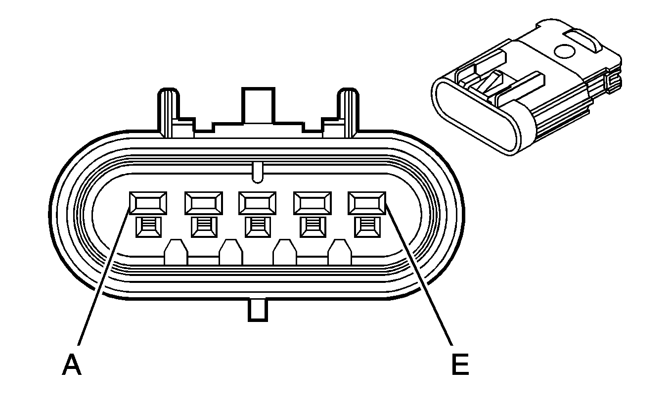
C101 Engine Harness to the Fuel Rail Harness (2.9L)
|
|
Connector Part Information
| Connector Part Information
|
Terminal Part Information
| Terminal Part Information
|
Pin | Wire Color | Circuit No. | Function | Pin | Wire Color | Circuit No. | Function |
|---|---|---|---|---|---|---|---|
A | PK | 839 | Ignition 1 Voltage | A | PK | 839 | Ignition 1 Voltage |
B | BK | 1744 | Fuel Injector 1 Control | B | BK | 1744 | Fuel Injector 1 Control |
C | L-GN/BK | 1745 | Fuel Injector 2 Control | C | L-GN/BK | 1745 | Fuel Injector 2 Control |
D | PK/BK | 1746 | Fuel Injector 3 Control | D | PK/BK | 1746 | Fuel Injector 3 Control |
E | L-BU/BK | 844 | Fuel Injector 4 Control | E | L-BU/BK | 844 | Fuel Injector 4 Control |
C101 Engine Harness to the Fuel Rail Harness (3.5L)
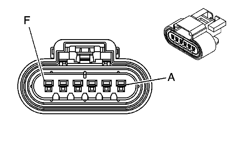
|
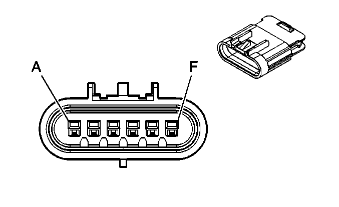
|
Connector Part Information
| Connector Part Information
|
Terminal Part Information
| Terminal Part Information
|
Pin | Wire Color | Circuit No. | Function | Pin | Wire Color | Circuit No. | Function |
|---|---|---|---|---|---|---|---|
A | PK | 839 | Ignition 1 Voltage | A | PK | 439 | Ignition 1 Voltage |
B | L-BU/BK | 844 | Fuel Injector 4 Control | B | L-BU/BK | 844 | Fuel Injector 4 Control |
C | BK/WH | 845 | Fuel Injector 5 Control | C | BK/WH | 845 | Fuel Injector 5 Control |
D | BK | 1744 | Fuel Injector 1 Control | D | BK | 1744 | Fuel Injector 1 Control |
E | L-GN/BK | 1745 | Fuel Injector 2 Control | E | L-GN/BK | 1745 | Fuel Injector 2 Control |
F | PK/BK | 1746 | Fuel Injector 3 Control | F | PK/BK | 1746 | Fuel Injector 3 Control |
C102 Body Harness to the Chassis Harness
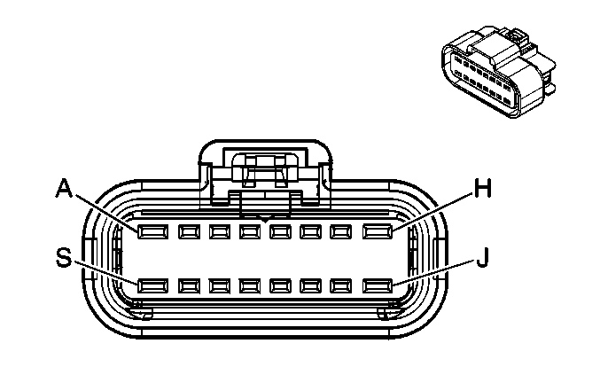
|
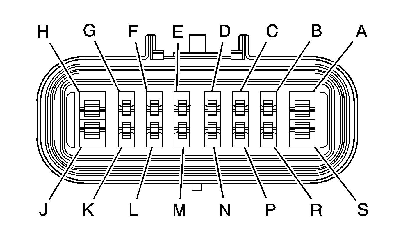
|
Connector Part Information
| Connector Part Information
|
Terminal Part Information
| Terminal Part Information
|
Pin | Wire Color | Circuit No. | Function | Pin | Wire Color | Circuit No. | Function |
|---|---|---|---|---|---|---|---|
A | GY | 120 | Fuel Pump Supply Voltage | A | GY | 120 | Fuel Pump Supply Voltage |
B | PU | 1589 | Fuel Level Sensor Signal - Primary | B | PU | 1589 | Fuel Level Sensor Signal |
C | BK | 2759 | Low Reference | C | BK | 2759 | Low Reference |
D | GY | 2709 | 5-Volt Reference | D | GY | 2709 | 5-Volt Reference |
E | D-GN | 890 | Fuel Tank Pressure Sensor Signal | E | D-GN | 890 | Fuel Tank Pressure Sensor Signal |
F | OG | 1640 | Battery Positive Voltage | F | OG | 1640 | Battery Positive Voltage |
G | WH | 1310 | EVAP Canister Vent Solenoid Control | G | WH | 1310 | EVAP Canister Vent Solenoid Control |
H | BK | 850 | Ground | H | BK | 850 | Ground |
J | BK | 850 | Ground | J | BK | 850 | Ground |
K | BN | 9 | Park Lamp Supply Voltage | K | BN | 9 | Park Lamp Supply Voltage |
L | D-GN | 19 | Right Rear Turn Signal Lamps Supply Voltage | L | D-GN | 19 | Right Rear Turn Signal Lamps Supply Voltage |
M | L-GN | 24 | Backup Lamp Supply Voltage | M | L-GN | 24 | Backup Lamp Supply Voltage |
N | L-BU | 20 | Stop Lamp Supply Voltage | N | L-BU | 20 | Stop Lamp Supply Voltage |
P | YE | 18 | Left Rear Turn Signal Lamps Supply Voltage | P | YE | 18 | Left Rear Turn Signal Lamps Supply Voltage |
R | BN | 9 | Park Lamp Supply Voltage | R | BN | 9 | Park Lamp Supply Voltage |
S | -- | -- | Not Used | S | -- | -- | Not Used |
C103 Forward Lamp Harness to the Body Harness
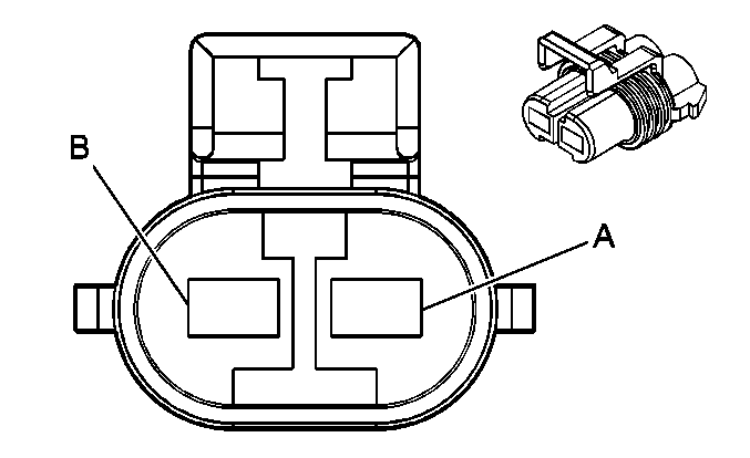
|
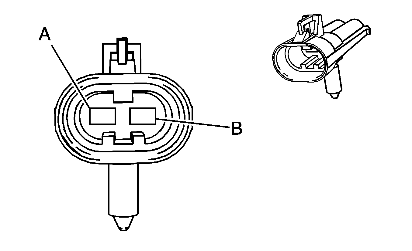
|
Connector Part Information
| Connector Part Information
|
Terminal Part Information
| Terminal Part Information
|
Pin | Wire Color | Circuit No. | Function | Pin | Wire Color | Circuit No. | Function |
|---|---|---|---|---|---|---|---|
A | L-BU | 14 | Left Turn Signal Lamps Supply Voltage | A | L-BU | 14 | Left Turn Signal Lamps Supply Voltage |
B | OG | 1840 | Battery Positive Voltage | B | OG | 1840 | Battery Positive Voltage (AG1/AG2) |
C104 Forward Lamp Harness to the Body Harness
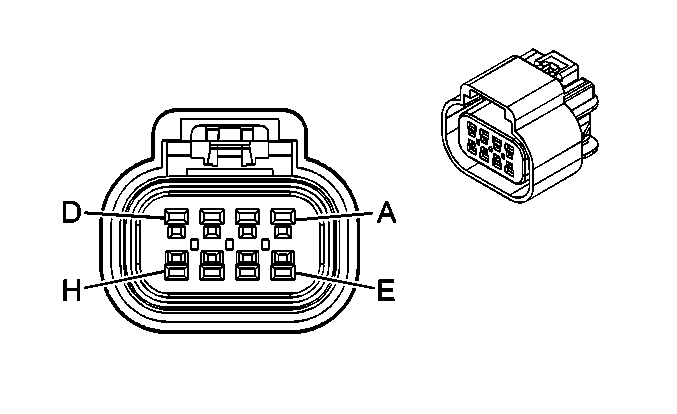
|
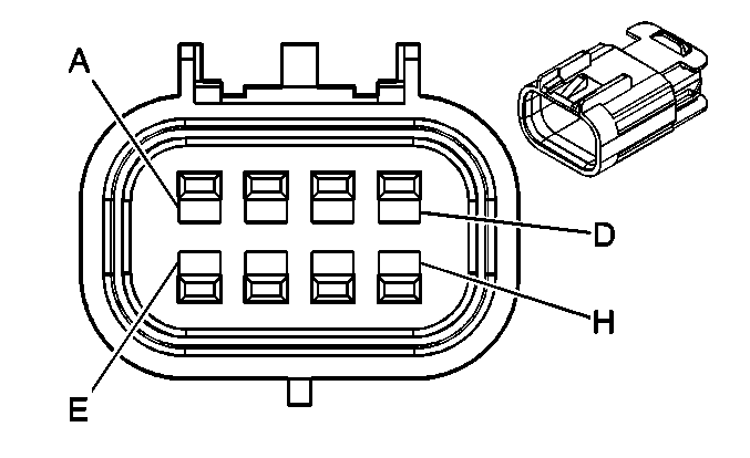
|
Connector Part Information
| Connector Part Information
|
Terminal Part Information
| Terminal Part Information
|
Pin | Wire Color | Circuit No. | Function | Pin | Wire Color | Circuit No. | Function |
|---|---|---|---|---|---|---|---|
A | D-GN | 1409 | Discriminating Sensor - Right - Signal | A | D-GN | 1409 | Discriminating Sensor - Right - Signal |
B | YE | 1834 | Front End Sensor - Voltage | B | YE | 1834 | Front End Sensor - Voltage |
C | D-BU | 15 | Right Turn Signal Lamps Supply Voltage | C | D-BU | 15 | Right Turn Signal Lamps Supply Voltage |
D | -- | -- | Not Used | D | -- | -- | Not Used |
E | YE | 354 | Discriminating Sensor - Signal | E | YE | 354 | Discriminating Sensor - Signal |
F | GY | 349 | Discriminating Sensor - Left - Signal | F | GY | 349 | Discriminating Sensor - Left - Signal |
G | YE | 61 | Low Reference (DF8) | G | YE | 61 | Low Reference (DF8) |
H | D-GN/WH | 636 | Ambient Air Temperature Sensor Signal (DF8) | H | D-GN/WH | 636 | Ambient Air Temperature Sensor Signal (DF8) |
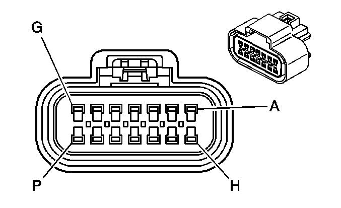
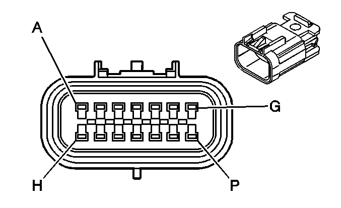
C105 Engine Harness to the Body Harness (4WD)
|
|
Connector Part Information
| Connector Part Information
|
Terminal Part Information
| Terminal Part Information
|
Pin | Wire Color | Circuit No. | Function | Pin | Wire Color | Circuit No. | Function |
|---|---|---|---|---|---|---|---|
A | BK | 1552 | Motor Control A | A | BK | 1552 | Motor Control A |
B | RD | 1553 | Motor Control B | B | RD | 1553 | Motor Control B |
C | TN | 1569 | 2WD/4WD Signal | C | TN | 1569 | 2WD/4WD Signal |
D | RD/WH | 1556 | Channel C Encoder - Signal | D | RD/WH | 1556 | Channel C Encoder - Signal |
E | GY | 2281 | Neutral Switch Signal | E | GY | 2281 | Neutral Switch Signal |
F | YE/BK | 1558 | Channel B Encoder - Signal | F | YE/BK | 1558 | Channel B Encoder - Signal |
G | BK/WH | 1695 | Axle Switch Signal | G | BK/WH | 1695 | Axle Switch Signal |
H | L-BU | 1296 | Axle Actuator - Control | H | L-BU | 1296 | Axle Actuator - Control |
J | D-BU/WH | 1557 | Channel A Encoder - Signal | J | D-BU/WH | 1557 | Channel A Encoder - Signal |
K | BN/WH | 1555 | Channel P Encoder - Signal | K | BN/WH | 1555 | Channel P Encoder - Signal |
L | BN | 436 | AIR Pump Relay Control | L | BN | 436 | AIR Pump Relay Control |
M | -- | -- | Not Used | M | -- | -- | Not Used |
N | PU | 1807 | Class 2 Serial Data | N | PU | 1807 | Class 2 Serial Data |
P | BN/WH | 6254 | ISS Signal | P | BN/WH | 6254 | ISS Signal |
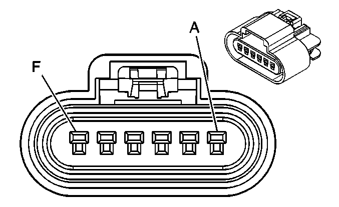
C106 Engine Harness to the Body Harness (2WD)
|

|
Connector Part Information
| Connector Part Information
|
Terminal Part Information
| Terminal Part Information
|
Pin | Wire Color | Circuit No. | Function | Pin | Wire Color | Circuit No. | Function |
|---|---|---|---|---|---|---|---|
A | OG/BK | 463 | Requested Torque Signal | A | OG/BK | 463 | Requested Torque Signal |
B | TN/BK | 464 | Delivered Torque Signal | B | TN/BK | 464 | Delivered Torque Signal |
C | BN | 436 | AIR Pump Relay Control | C | BN | 436 | AIR Pump Relay Control |
D | -- | -- | Not Used | D | -- | -- | Not Used |
E | PU | 1807 | Class 2 Serial Data | E | PU | 1807 | Class 2 Serial Data |
F | BN/WH | 6254 | ISS Signal | F | BN/WH | 6254 | ISS Signal |
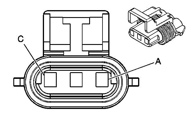
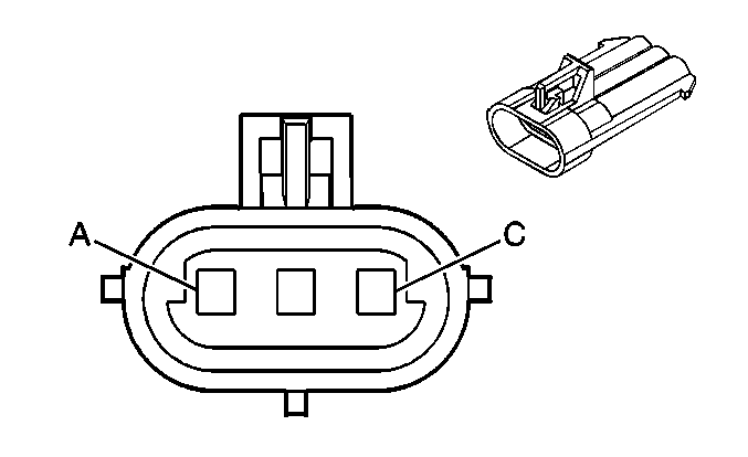
C107 Forward Lamp Harness to Right Front Turn Signal Harness
|
|
Connector Part Information
| Connector Part Information
|
Terminal Part Information
| Terminal Part Information
|
Pin | Wire Color | Circuit No. | Function | Pin | Wire Color | Circuit No. | Function |
|---|---|---|---|---|---|---|---|
A | BN | 9 | Park Lamp Supply Voltage | A | BN | -- | Park Lamp Supply Voltage |
B | D-BU | 15 | Right Turn Signal Lamps Supply Voltage | B | L-BU | -- | Right Turn Signal Lamps Supply Voltage |
C | BK | 850 | Ground | C | BK | -- | Ground |
C108 Forward Lamp Harness to Left Front Turn Signal Harness

|

|
Connector Part Information
| Connector Part Information
|
Terminal Part Information
| Terminal Part Information
|
Pin | Wire Color | Circuit No. | Function | Pin | Wire Color | Circuit No. | Function |
|---|---|---|---|---|---|---|---|
A | BN | 9 | Park Lamp Supply Voltage | A | BN | -- | Park Lamp Supply Voltage |
B | L-BU | 14 | Left Turn Signal Supply Lamps Voltage | B | L-BU | -- | Left Turn Signal Supply Lamps Voltage |
C | BK | 850 | Ground | C | BK | -- | Ground |
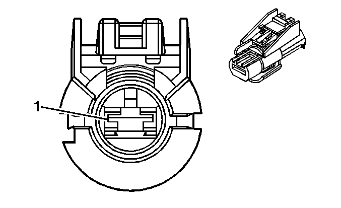
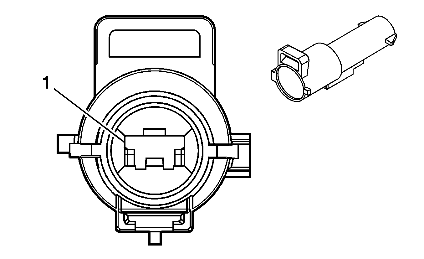
C109 Battery Harness to Engine Harness
|
|
Connector Part Information
| Connector Part Information
|
Terminal Part Information
| Terminal Part Information
|
Pin | Wire Color | Circuit No. | Function | Pin | Wire Color | Circuit No. | Function |
|---|---|---|---|---|---|---|---|
1 | RD | 8 | Battery Positive Voltage | 1 | RD | 5 | Battery Positive Voltage |
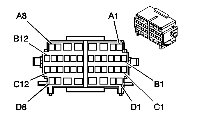
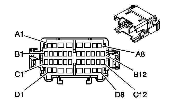
C200 I/P Harness to the Body Harness
|
|
Connector Part Information
| Connector Part Information
|
Terminal Part Information
| Terminal Part Information
|
Pin | Wire Color | Circuit No. | Function | Pin | Wire Color | Circuit No. | Function |
|---|---|---|---|---|---|---|---|
A1 | -- | -- | Not Used | A1 | -- | -- | Not Used |
A2 | D-GN | 2308 | Passenger Airbag On Indicator Control | A2 | D-GN | 2308 | Passenger Airbag On Indicator Control |
A3 | L-BU/BK | 1693 | Switch Signal Low (4WD) | A3 | L-BU | 1693 | Switch Signal Low (4WD) |
A4 | BK/WH | 1151 | Ground | A4 | BK/WH | 1151 | Not Used |
A5 | OG | 40 | Battery Positive Voltage | A5 | OG | 40 | Battery Positive Voltage |
OG | 40 | Battery Positive Voltage | |||||
A6 | PK | 339 | Ignition 1 Voltage | A6 | PK | 339 | Ignition 1 Voltage |
PK | 339 | Ignition 1 Voltage (4WD) | |||||
A7 | -- | -- | Not Used | A7 | -- | -- | Not Used |
A8 | BN | 141 | Ignition 3 Voltage | A8 | BN | 141 | Ignition 3 Voltage |
B1 | OG | 1440 | Battery Positive Voltage | B1 | OG | 1440 | Battery Positive Voltage |
B2-B3 | -- | -- | Not Used | B2-B3 | -- | -- | Not Used |
B4 | GY | 91 | Windshield Wiper Relay Control | B4 | GY | 91 | Windshield Wiper Relay Control |
B5 | GY/BK | 1694 | 5-Volt Reference (4WD) | B5 | GY/BK | 1694 | 5-Volt Reference (4WD) |
B6 | GY | 1884 | Cruise Control Set/Coast and Resume/Accelerate Switch Signal (K34) | B6 | GY | 1884 | Cruise Control Set/Coast and Resume/Accelerate Switch Signal (K34) |
B7 | -- | -- | Not Used | B7 | -- | -- | Not Used |
B8 | BN | 1560 | Neutral Indicator Control (4WD) | B8 | BN | 1560 | Neutral Indicator Control (4WD) |
B9 | L-GN/BK | 1563 | 2 HI Indicator - Control (4WD) | B9 | L-GN/BK | 1563 | 2 HI Indicator - Control (4WD) |
B10-B11 | -- | -- | Not Used | B10-B11 | -- | -- | Not Used |
B12 | YE | 116 | Left Rear Speaker Output (-) (Extended/Crew Cab) | B12 | YE | 116 | Left Rear Speaker Output (-) (Extended/Crew Cab) |
C1 | BN | 199 | Left Rear Speaker Output (+) (Extended/Crew Cab) | C1 | BN | 199 | Left Rear Speaker Output (+) (Extended/Crew Cab) |
C2 | OG | 1740 | Battery Positive Voltage | C2 | OG | 1740 | Battery Positive Voltage |
C3-C6 | -- | -- | Not Used | C3-C6 | -- | -- | Not Used |
C7 | PU/WH | 1565 | 4 LO Indicator - Control (4WD) | C7 | PU/WH | 1565 | 4 LO Indicator - Control (4WD) |
C8 | -- | -- | Not Used | C8 | -- | -- | Not Used |
C9 | BN | 9 | Park Lamp Supply Voltage | C9 | BN | 9 | Park Lamp Supply Voltage |
C10 | TN/BK | 1566 | 4 HI Indicator - Control (4WD) | C10 | TN/BK | 1566 | 4 HI Indicator - Control (4WD) |
C11 | -- | -- | Not Used | C11 | -- | -- | Not Used |
C12 | D-BU | 2307 | Passenger Airbag On Indicator Control | C12 | D-BU | 2307 | Passenger Airbag On Indicator Control |
D1 | OG | 240 | Battery Positive Voltage (KC5) | D1 | OG | 240 | Battery Positive Voltage (KC5) |
D2-D3 | -- | -- | Not Used | D2-D3 | -- | -- | Not Used |
D4 | GY | 118 | Left Front Speaker Output (-) | D4 | GY | 118 | Left Front Speaker Output (-) |
D4 | GY | 118 | Left Front Speaker Output (-) | D4 | GY | 118 | Left Front Speaker Output (-) (UQ3) |
D5 | TN | 201 | Left Front Speaker Output (+) | D5 | TN | 201 | Left Front Speaker Output (+) |
TN | 201 | Left Front Speaker Output (+) (UQ3) | |||||
D6 | OG | 1140 | Battery Positive Voltage | D6 | OG | 1140 | Battery Positive Voltage |
OG | 1140 | Battery Positive Voltage (U2K) | |||||
D7 | -- | -- | Not Used | D7 | -- | -- | Not Used |
D8 | YE | 143 | Accessory Voltage | D8 | YE | 143 | Accessory Voltage |
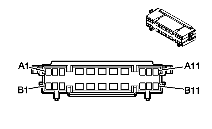
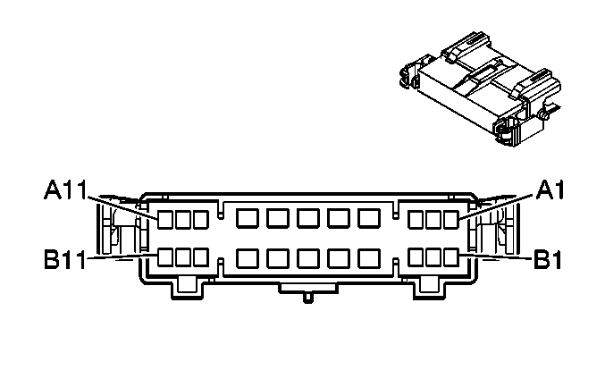
C201 I/P Harness to the Body Harness
|
|
Connector Part Information
| Connector Part Information
|
Terminal Part Information
| Terminal Part Information
|
Pin | Wire Color | Circuit No. | Function | Pin | Wire Color | Circuit No. | Function |
|---|---|---|---|---|---|---|---|
A1 | BN/WH | 419 | MIL Control | A1 | BN/WH | 419 | MIL Control |
A2 | D-GN/WH | 2514 | Keypad Signal (UE1) | A2 | D-GN/WH | 2514 | Keypad Signal (UE1) |
A3 | L-GN/BK | 2515 | Keypad Supply Voltage (UE1) | A3 | L-GN/BK | 2515 | Keypad Supply Voltage (UE1) |
A4 | BK | 2050 | Ground | A4 | BK | 2050 | Ground |
A5 | BK | 2050 | Ground | A5 | BK | 2050 | Ground |
A6 | -- | -- | Not Used | A6 | -- | -- | Not Used |
A7 | OG | 340 | Battery Positive Voltage (UE1) | A7 | OG | 340 | Battery Positive Voltage (UE1) |
A8 | BN | 41 | Ignition 3 Voltage | A8 | BN | 41 | Ignition 3 Voltage |
A9 | D-GN/WH | 762 | A/C Request Signal (C60) | A9 | D-GN/WH | 762 | A/C Request Signal (C60) |
A10 | GY | 655 | Cellular Microphone Signal (UE1) | A10 | GY | 655 | Cellular Microphone Low Reference (UE1) |
A11 | BARE | 1705 | Drain Wire (UE1) | A11 | BARE | 1705 | Drain Wire (UE1) |
B1-B3 | -- | -- | Not Used | B1-B3 | -- | -- | Not Used |
B4 | YE/BK | 2516 | Keypad Green LED Signal (UE1) | B4 | YE/BK | 2516 | Keypad Green LED Signal (UE1) |
B5 | BN/WH | 2517 | Keypad Red LED Signal (UE1) | B5 | BN/WH | 2517 | Keypad Red LED Signal (UE1) |
B6 | -- | -- | Not Used | B6 | -- | -- | Not Used |
B7 | D-GN | 117 | Right Front Speaker Output (-) | B7 | D-GN | 117 | Right Front Speaker Output (-) |
D-GN | 117 | Right Front Speaker Output (-) | |||||
B8 | L-GN | 200 | Right Front Speaker Output (+) | B8 | L-GN | 200 | Right Front Speaker Output (+) |
L-GN | 200 | Right Front Speaker Output (+) (UQ3) | |||||
B9 | PU | 1807 | Class 2 Serial Data (UE1) | B9 | PU | 1807 | Class 2 Serial Data (UE1) |
B10 | D-BU | 46 | Right Rear Speaker Output (+) | B10 | D-BU | 46 | Right Rear Speaker Output (+) |
B11 | L-BU | 115 | Right Rear Speaker Output (-) | B11 | L-BU | 115 | Right Rear Speaker Output (-) |
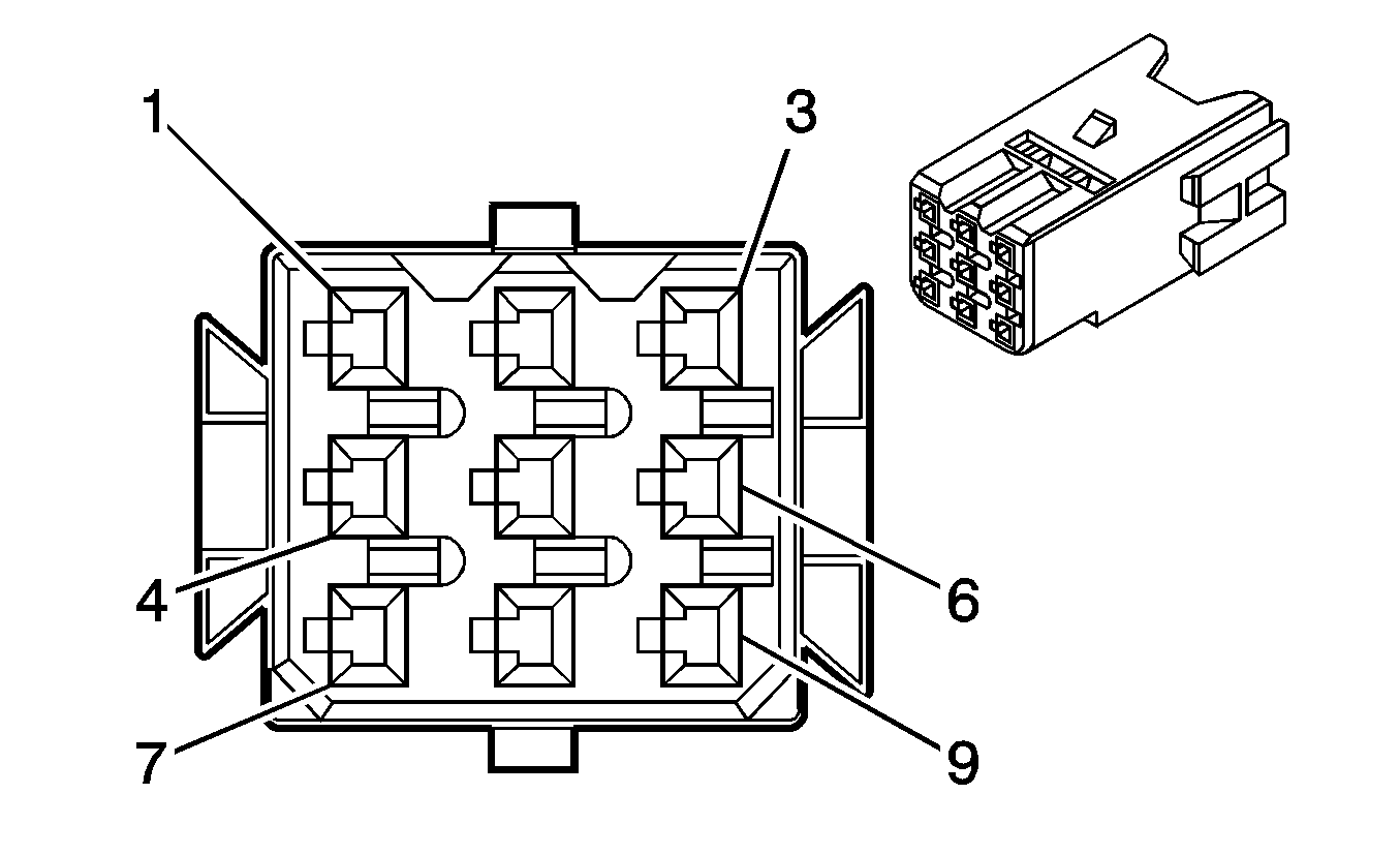
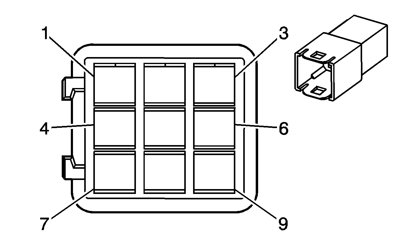
C202 Driver Door Harness to the Body Harness (AU3)
|
|
Connector Part Information
| Connector Part Information
|
Terminal Part Information
| Terminal Part Information
|
Pin | Wire Color | Circuit No. | Function | Pin | Wire Color | Circuit No. | Function |
|---|---|---|---|---|---|---|---|
1 | BN | 9 | Park Lamp Supply Voltage | 1 | BN | 9 | Park Lamp Supply Voltage |
BN | 9 | Park Lamp Supply Voltage | |||||
2 | YE | 443 | Accessory Voltage | 2 | YE | 443 | Accessory Voltage |
3 | GY | 295 | Door Lock Actuator Lock Control | 3 | GY | 295 | Door Lock Actuator Lock Control |
GY | 295 | Door Lock Actuator Lock Control | |||||
4 | BK | 850 | Ground (ZQ6) | 4 | BK | 850 | Ground (ZQ6) |
5 | -- | -- | Not Used | 5 | -- | -- | Not Used |
6 | L-BU | 244 | Passenger Door Lock Switch Lock Control | 6 | L-BU | 244 | Passenger Door Lock Switch Lock |
L-BU | 244 | Passenger Door Lock Switch Lock | |||||
7 | WH | 194 | Door Unlock Control | 7 | WH | 194 | Door Unlock Control |
8 | OG | 1240 | Battery Positive Voltage | 8 | OG | 1240 | Battery Positive Voltage |
9 | TN | 294 | Door Lock Actuator Unlock Control | 9 | TN | 294 | Door Lock Actuator Unlock Control |
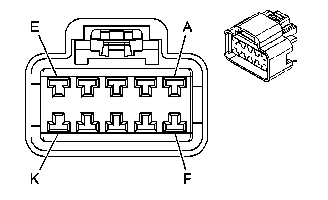
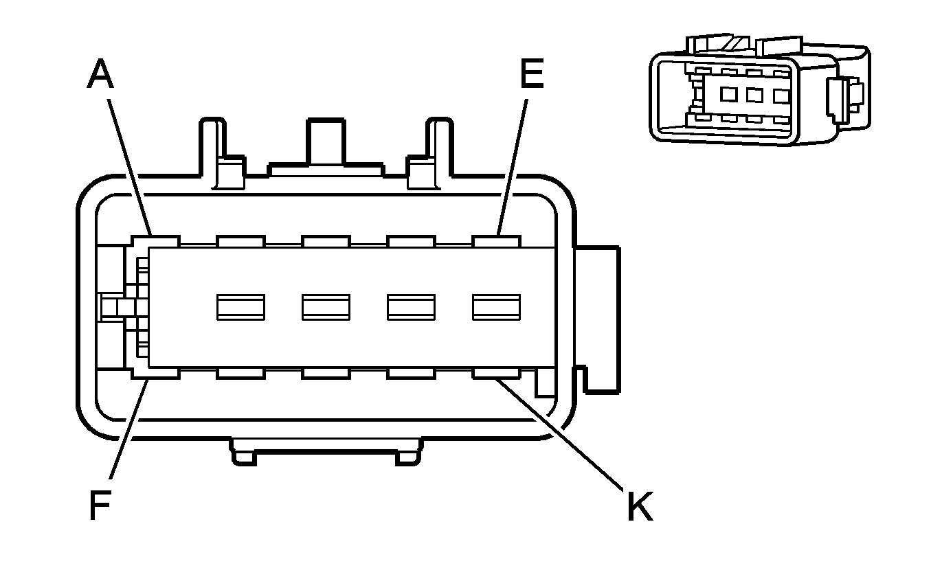
C203 I/P Harness to the HVAC Harness
|
|
Connector Part Information
| Connector Part Information
|
Terminal Part Information
| Terminal Part Information
|
Pin | Wire Color | Circuit No. | Function | Pin | Wire Color | Circuit No. | Function |
|---|---|---|---|---|---|---|---|
A | YE | 60 | Blower Motor Low Control | A | YE | 60 | Blower Motor Low Control |
B | L-GN/BK | 1647 | Recirculation Door Control B | B | L-GN/BK | 1647 | Recirculation Door Control B (C60) |
C | TN | 63 | Blower Motor Medium 1 Control | C | TN | 63 | Blower Motor Medium 1 Control |
D | PK/WH | 1648 | Recirculation Door Control A | D | PK/WH | 1648 | Recirculation Door Control A (C60) |
E | L-BU | 72 | Medium 2 Blower Motor Control | E | L-BU | 72 | Medium 2 Blower Motor Control |
F | L-GN | 66 | A/C Request Signal | F | L-GN | 66 | A/C Request Signal (C60) |
G | OG | 52 | Blower Motor High Control | G | OG | 52 | Blower Motor High Control |
H | D-GN/WH | 762 | A/C Request Signal | H | D-GN/WH | 762 | A/C Request Signal (C60) |
J | BN | 41 | Ignition 3 Voltage | J | BN | 41 | Ignition 3 Voltage |
K | BK | 2050 | Ground | K | BK | 2050 | Ground (C60) |
C204 Steering Column Harness to the I/P Harness

|

|
Connector Part Information
| Connector Part Information
|
Terminal Part Information
| Terminal Part Information
|
Pin | Wire Color | Circuit No. | Function | Pin | Wire Color | Circuit No. | Function |
|---|---|---|---|---|---|---|---|
A1 | WH/BU | 1390 | Off/Run/Crank Voltage | A1 | WH | 1390 | Off/Run/Crank Voltage |
A2 | WH/GN | 338 | Run/Crank Voltage | A2 | D-BU | 338 | Run/Crank Voltage |
A3 | WH/RD | 4 | Accessory Voltage | A3 | BN | 4 | Accessory Voltage |
A4 | GY | 323 | Shift Solenoid Supply Voltage | A4 | BN | 323 | Shift Solenoid Supply Voltage |
A5 | BN | 228 | Windshield Washer Pump Control | A5 | RD | 228 | Windshield Washer Pump Control |
A6 | D-BU/BK | 91 | Windshield Wiper Relay Control | A6 | GY | 91 | Windshield Wiper Relay Control |
A7 | D-BU/RD | 112 | Windshield Wiper Switch Signal 1 | A7 | GY | 112 | Windshield Wiper Switch Signal 1 |
A8 | YE | 339 | Ignition 1 Voltage | A8 | PK | 339 | Ignition 1 Voltage |
PK | 339 | Ignition 1 Voltage | |||||
A9 | -- | -- | Not Used | A9 | -- | -- | Not Used |
A10 | D-BU/WH | 1356 | Flash-To-Pass Switch Signal | A10 | BN | 1356 | Flash-To-Pass Switch Signal |
A11 | RD | 524 | Headlamp Dimmer Switch High Beam Signal | A11 | PU | 524 | Headlamp Dimmer Switch High Beam Signal |
B1 | WH/YE | 1073 | Ignition Key Resistor Signal | B1 | WH/BK | 1073 | Ignition Key Resistor Signal |
B2 | -- | -- | Not Used | B2 | -- | -- | Not Used |
B3 | WH/BK | 1740 | Battery Positive Voltage | B3 | OG | 1740 | Battery Positive Voltage |
B4 | D-BU | 2050 | Ground | B4 | BK | 2050 | Ground |
B5 | PU | 1508 | Turn Signal Switch Signal | B5 | L-BU | 1508 | Turn Signal Switch Signal |
B6 | -- | -- | Not Used | B6 | -- | -- | Not Used |
B7 | BK | 143 | Accessory Voltage | B7 | YE | 143 | Accessory Voltage |
B8 | WH | 1884 | Cruise Control Set/Coast and Resume/Accelerate Switch Signal | B8 | GY | 1884 | Cruise Control Set/Coast and Resume/Accelerate Switch Signal |
B9 | D-GN | 2050 | Ground | B9 | BK | 2050 | Ground |
B10 | PK | 2050 | Ground | B10 | BK | 2050 | Ground |
B11 | L-GN | 28 | Horn Relay Control | B11 | BK | 28 | Horn Relay Control |
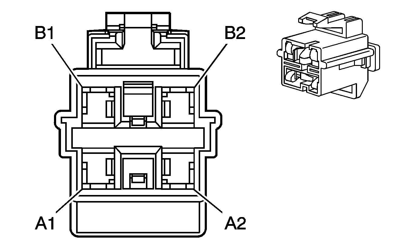
C208 I/P Harness to the Body Harness
|
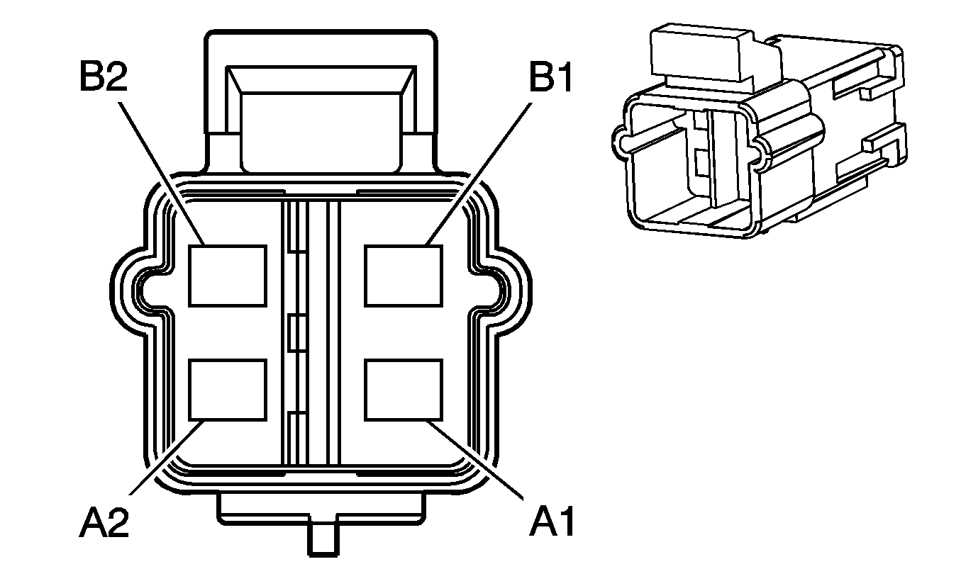
|
Connector Part Information
| Connector Part Information
|
Terminal Part Information
| Terminal Part Information
|
Pin | Wire Color | Circuit No. | Function | Pin | Wire Color | Circuit No. | Function |
|---|---|---|---|---|---|---|---|
A1 | OG | 3024 | I/P Module - Stage 1 - Low Control | A1 | OG | 3024 | I/P Module - Stage 1 - Low Control |
A2 | YE | 3025 | I/P Module - Stage 1 - High Control | A2 | YE | 3025 | I/P Module - Stage 1 - High Control |
B1 | GY | 3027 | I/P Module - Stage 2 - High Control | B1 | GY | 3027 | I/P Module - Stage 2 - High Control |
B2 | PU | 3026 | I/P Module - Stage 2 - Low Control | B2 | PU | 3026 | I/P Module - Stage 2 - Low Control |
C209 Body Harness to the Driver Door Harness
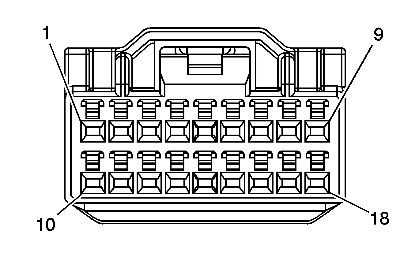
|
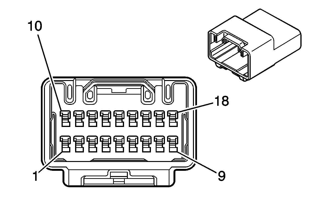
|
Connector Part Information
| Connector Part Information
|
Terminal Part Information
| Terminal Part Information
|
Pin | Wire Color | Circuit No. | Function | Pin | Wire Color | Circuit No. | Function |
|---|---|---|---|---|---|---|---|
1 | RD/WH | 881 | Passenger Mirror Motor Right Control (A31) | 1 | RD/WH | 881 | Passenger Mirror Motor Right Control (A31) |
2 | D-BU | 1307 | Power Window Master Switch Lockout Signal (A31) | 2 | D-BU | 1307 | Power Window Master Switch Lockout Signal (A31) |
3 | BN/WH | 1498 | Passenger Mirror Motor Up Control (DE6) | 3 | BN/WH | 1498 | Passenger Mirror Motor Up Control (DE6) |
4 | TN | 201 | Left Front Speaker Output (+) (UQ3) | 4 | TN | 201 | Left Front Speaker Output (+) (UQ3) |
5 | GY | 118 | Left Front Speaker Output (-) (UQ3) | 5 | GY | 118 | Left Front Speaker Output (-) (UQ3) |
6 | TN | 167 | Power Window Master Switch Right Front Down Signal (A31) | 6 | TN | 167 | Power Window Master Switch Right Front Down Signal (A31) |
7 | D-GN | 168 | Power Window Master Switch Left Rear Up Signal (Crew Cab) (A31) | 7 | D-GN | 168 | Power Window Master Switch Left Rear Up Signal (Crew Cab) (A31) |
8 | L-BU | 166 | Power Window Master Switch Right Front Up Signal (A31) | 8 | L-BU | 166 | Power Window Master Switch Right Front Up Signal (A31) |
9 | L-GN | 170 | Power Window Master Switch Right Rear Up Signal (A31) | 9 | L-GN | 170 | Power Window Master Switch Right Rear Up Signal (Crew Cab) (A31) |
10 | YE | 1187 | Power Window Master Switch Left Rear Down Signal (Crew Cab) (A31) | 10 | YE | 1187 | Power Window Master Switch Left Rear Down Signal (Crew Cab) (A31) |
11 | TN | 201 | Left Front Speaker Output (+) | 11 | TN | 201 | Left Front Speaker Output (+) |
12 | GY | 118 | Left Front Speaker Output (-) | 12 | GY | 118 | Left Front Speaker Output (-) |
13 | YE | 2131 | Side Impact Sensing Module - Left -Voltage (ASF) | 13 | YE | 2131 | Side Impact Sensing Module - Left -Voltage (ASF) |
14 | WH | 2132 | Side Impact Sensing Module - Left - Signal (ASF) | 14 | WH | 2132 | Side Impact Sensing Module - Left - Signal (ASF) |
15 | OG | 1732 | Courtesy Lamps Supply Voltage | 15 | OG | 1732 | Courtesy Lamps Supply Voltage |
16 | D-BU | 245 | Passenger Door Lock Switch Unlock Control (A31) | 16 | D-BU | 245 | Passenger Door Lock Switch Unlock Control (A31) |
17 | L-BU/WH | 1497 | Passenger Mirror Motor Left/Down Control (DE6) | 17 | L-BU/WH | 1497 | Passenger Mirror Motor Left/Down Control (DE6) |
18 | PU | 171 | Power Window Master Switch Right Rear Down Signal (Crew Cab) (A31) | 18 | PU | 171 | Power Window Master Switch Right Rear Down Signal (Crew Cab) (A31) |
C210 Body Harness to the Passenger Door Harness

|

|
Connector Part Information
| Connector Part Information
|
Terminal Part Information
| Terminal Part Information
|
Pin | Wire Color | Circuit No. | Function | Pin | Wire Color | Circuit No. | Function |
|---|---|---|---|---|---|---|---|
1 | RD/WH | 881 | Passenger Mirror Motor Right Control (DE6) | 1 | RD/WH | 881 | Passenger Mirror Motor Right Control (DE6) |
2 | D-BU | 1307 | Power Window Master Switch Lockout Signal (A31) | 2 | D-BU | 1307 | Power Window Master Switch Lockout Signal (A31) |
3 | BN/WH | 1498 | Passenger Mirror Motor Up Control (DE6) | 3 | BN/WH | 1498 | Passenger Mirror Motor Up Control (DE6) |
4 | L-GN | 200 | Right Front Speaker Output (+) | 4 | L-GN | 200 | Right Front Speaker Output (+) (UQ3) |
5 | D-GN | 117 | Right Front Speaker Output (-) | 5 | D-GN | 117 | Right Front Speaker Output (-) (UQ3) |
6 | TN | 167 | Power Window Master Switch Right Front Down Signal (A31) | 6 | TN | 167 | Power Window Master Switch Right Front Down Signal (A31) |
7 | BN | 9 | Park Lamp Supply Voltage (A31) | 7 | BN | 9 | Park Lamp Supply Voltage (A31) |
8 | L-BU | 166 | Power Window Master Switch Right Front Up Signal (A31) | 8 | L-BU | 166 | Power Window Master Switch Right Front Up Signal (A31) |
9 | -- | -- | Not Used | 9 | -- | -- | Not Used |
10 | L-BU | 244 | Passenger Door Lock Switch Lock Control (A31) | 10 | L-BU | 244 | Passenger Door Lock Switch Lock Control (A31) |
11 | L-GN | 200 | Right Front Speaker Output (+) | 11 | L-GN | 200 | Right Front Speaker Output (+) |
12 | D-GN | 117 | Right Front Speaker Output (-) | 12 | D-GN | 117 | Right Front Speaker Output (-) |
13 | TN | 2133 | Side Impact Sensing Module - Right - Voltage (ASF) | 13 | TN | 2133 | Side Impact Sensing Module - Right - Voltage (ASF) |
14 | D-GN | 2134 | Side Impact Sensing Module - Right - Signal (ASF) | 14 | D-GN | 2134 | Side Impact Sensing Module - Right - Signal (ASF) |
15 | -- | -- | Not Used | 15 | -- | -- | Not Used |
16 | D-BU | 245 | Passenger Door Lock Switch Unlock Control (A31) | 16 | D-BU | 245 | Passenger Door Lock Switch Unlock Control (A31) |
17 | L-BU/WH | 1497 | Passenger Mirror Motor Left/Down Control (A31) | 17 | L-BU/WH | 1497 | Passenger Mirror Motor Left/Down Control (A31) |
18 | -- | -- | Not Used | 18 | -- | -- | Not Used |
C211 Passenger Door Harness to the Body Harness (AU3)

|

|
Connector Part Information
| Connector Part Information
|
Terminal Part Information
| Terminal Part Information
|
Pin | Wire Color | Circuit No. | Function | Pin | Wire Color | Circuit No. | Function |
|---|---|---|---|---|---|---|---|
1 | -- | -- | Not Used | 1 | -- | -- | Not Used |
2 | YE | 443 | Accessory Voltage | 2 | YE | 443 | Accessory Voltage |
3 | GY | 295 | Door Lock Actuator Lock Control | 3 | GY | 295 | Door Lock Actuator Lock Control |
4 | BK | 2050 | Ground | 4 | BK | 2050 | Ground |
5-8 | -- | -- | Not Used | 5-8 | -- | -- | Not Used |
9 | TN | 294 | Door Lock Actuator Unlock Control | 9 | TN | 294 | Door Lock Actuator Unlock Control |
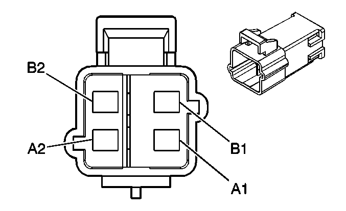
C275 SIR Coil Harness to the Body Harness
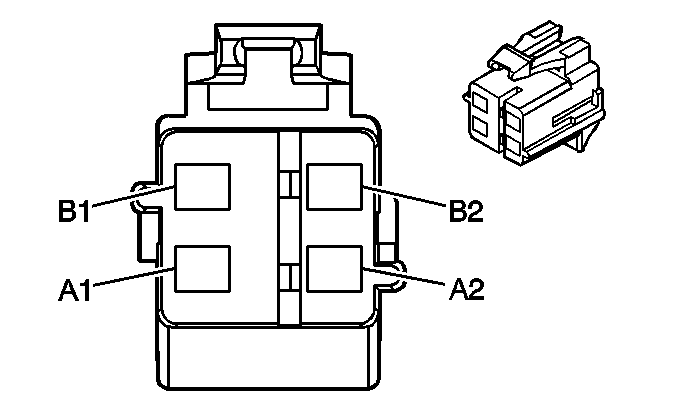
|
|
Connector Part Information
| Connector Part Information
|
Terminal Part Information
| Terminal Part Information
|
Pin | Wire Color | Circuit No. | Function | Pin | Wire Color | Circuit No. | Function |
|---|---|---|---|---|---|---|---|
A1 | YE | -- | Steering Wheel Module - Stage 1 - High Control | A1 | TN | 3021 | Steering Wheel Module - Stage 1 - High Control |
A2 | BN | -- | Steering Wheel Module - Stage 1 - Low Control | A2 | BN | 3020 | Steering Wheel Module - Stage 1 - Low Control |
B1 | RD | -- | Steering Wheel Module - Stage 2 - High Control | B1 | WH | 3023 | Steering Wheel Module - Stage 2 - High Control |
B2 | WH | -- | Steering Wheel Module - Stage 2 - Low Control | B2 | PK | 3022 | Steering Wheel Module - Stage 2 - Low Control |
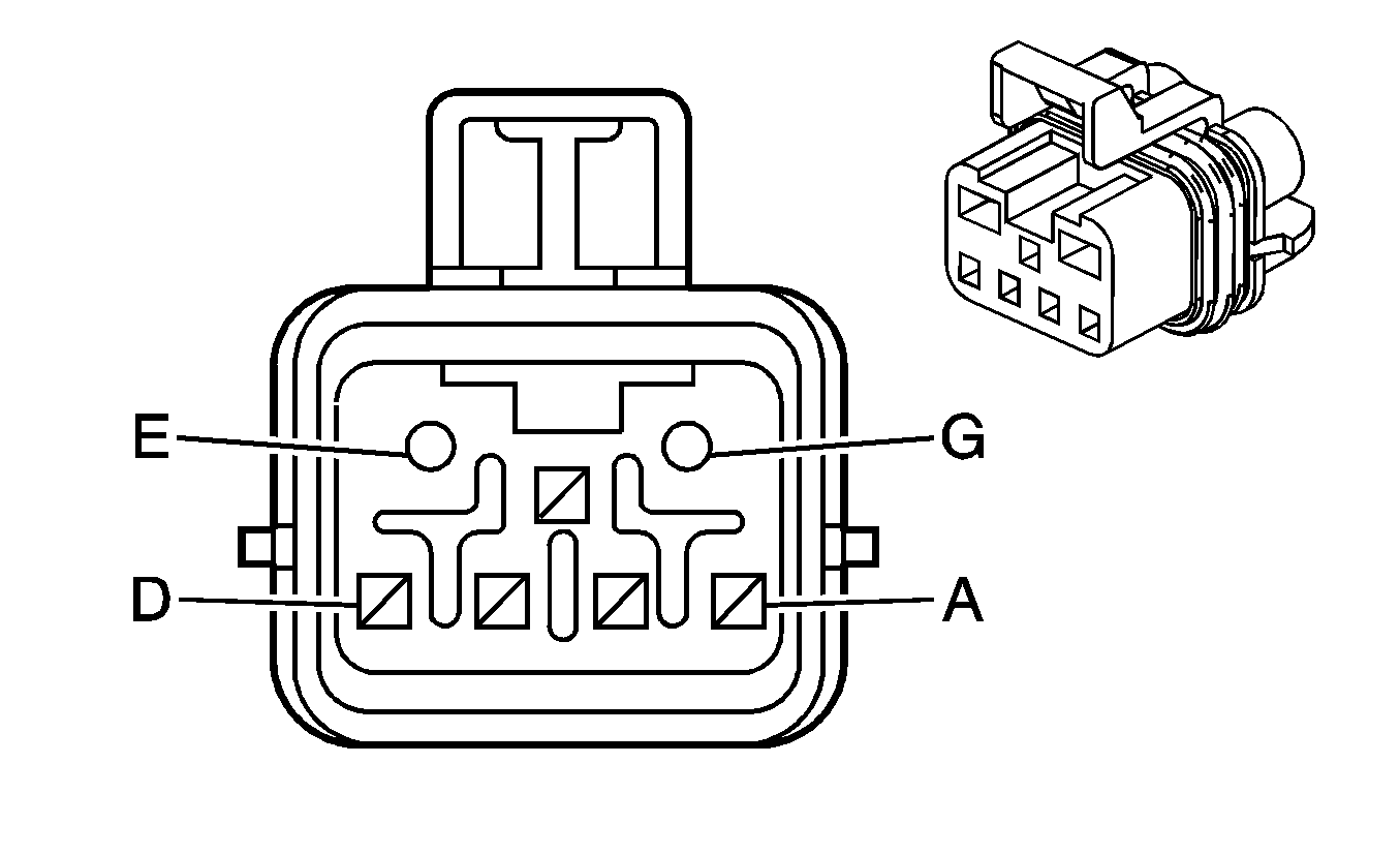
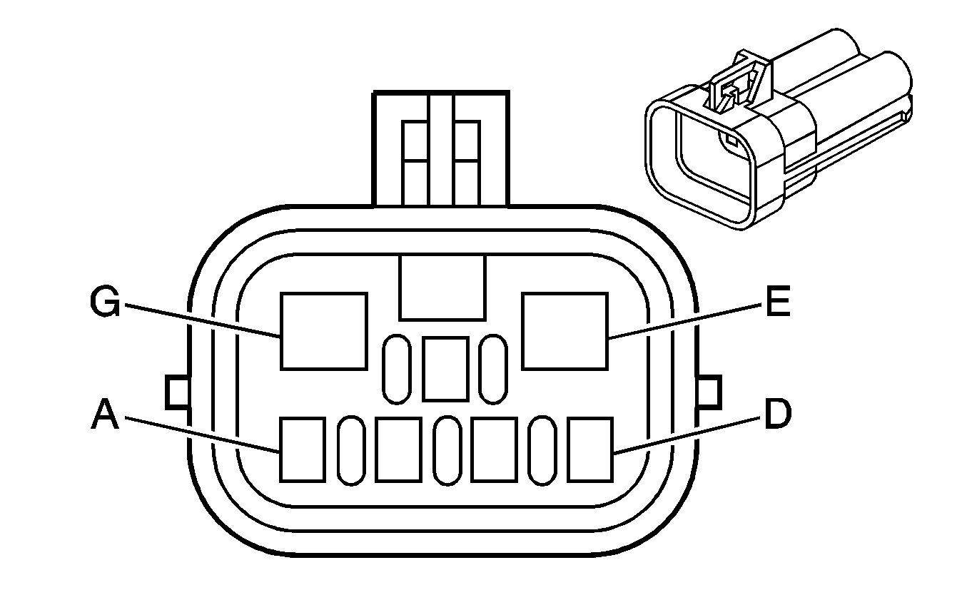
C307 Body Harness to the Driver Seat Harness (AG1)
|
|
Connector Part Information
| Connector Part Information
|
Terminal Part Information
| Terminal Part Information
|
Pin | Wire Color | Circuit No. | Function | Pin | Wire Color | Circuit No. | Function |
|---|---|---|---|---|---|---|---|
A | BN | 141 | Ignition 3 Voltage | A | BN | 141 | Ignition 3 Voltage |
B | OG | 1040 | Battery Positive Voltage | B | OG | 1040 | Battery Positive Voltage |
C | BK | 2050 | Ground | C | BK | 2050 | Ground |
D | OG | 2240 | Battery Positive Voltage | D | OG | 2240 | Battery Positive Voltage |
E-F | -- | -- | Not Used | E-F | -- | -- | Not Used |
G | OG | 1840 | Battery Positive Voltage | G | OG | 1840 | Battery Positive Voltage |
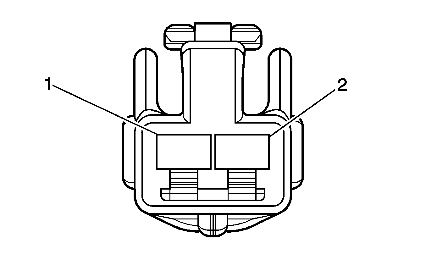
C310 Dome Lamp Harness to the Body Harness
|
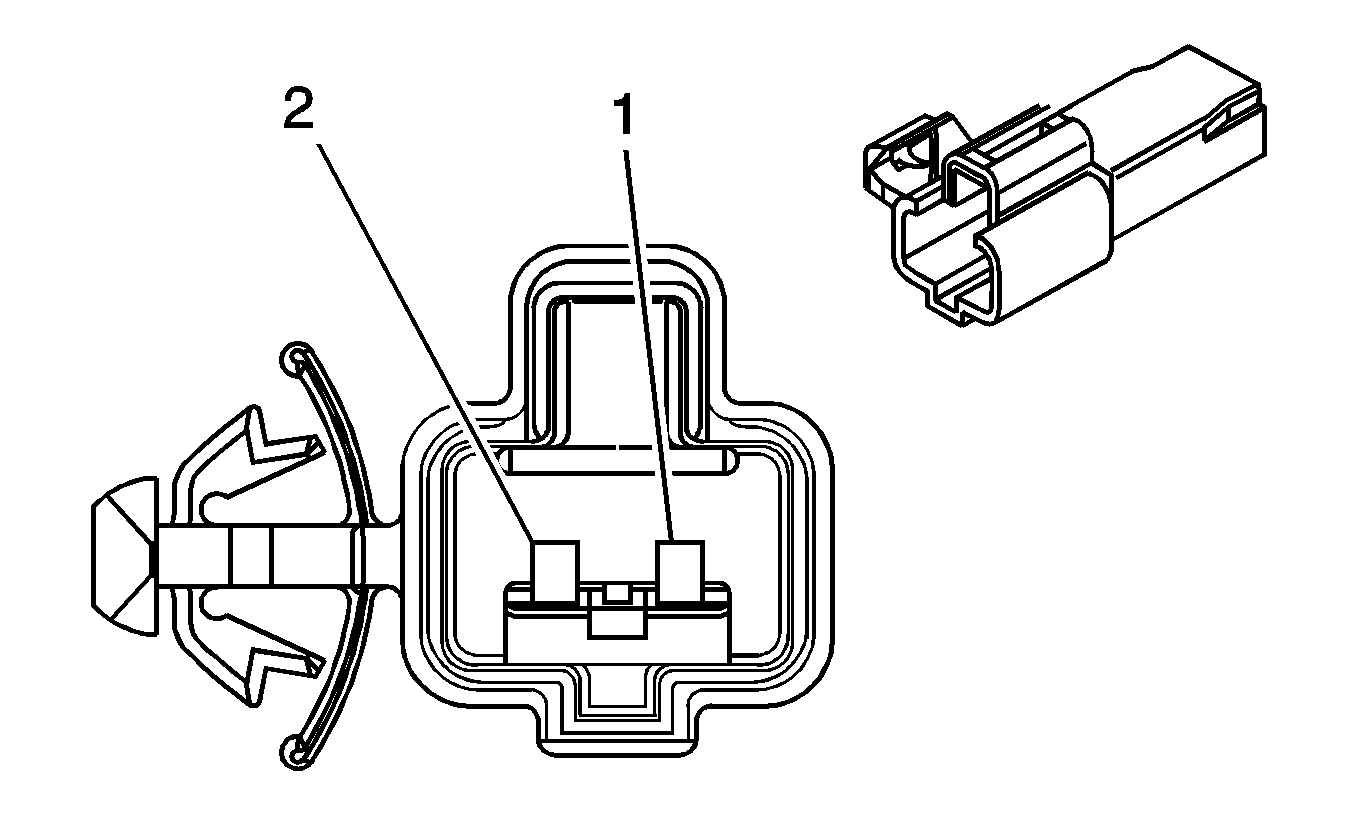
|
Connector Part Information
| Connector Part Information
|
Terminal Part Information
| Terminal Part Information
|
Pin | Wire Color | Circuit No. | Function | Pin | Wire Color | Circuit No. | Function |
|---|---|---|---|---|---|---|---|
1 | OG | 1732 | Courtesy Lamps Supply Voltage | 1 | OG | 1732 | Courtesy Lamps Supply Voltage |
OG | 1732 | Courtesy Lamps Supply Voltage | |||||
2 | WH | 156 | Courtesy Lamp Low Control | 2 | WH | 156 | Courtesy Lamp Low Control |
C311 Body Harness to the Right Rear Passenger Door Harness (Extended Cab)
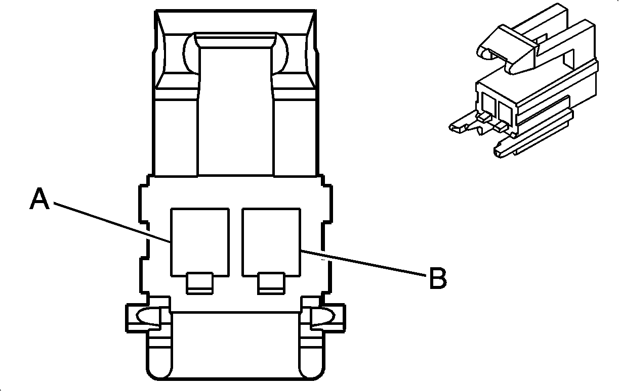
|
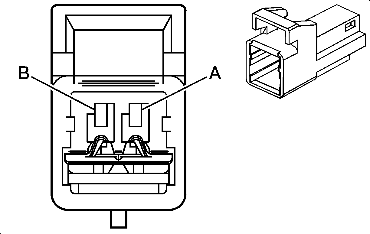
|
Connector Part Information
| Connector Part Information
|
Terminal Part Information
| Terminal Part Information
|
Pin | Wire Color | Circuit No. | Function | Pin | Wire Color | Circuit No. | Function |
|---|---|---|---|---|---|---|---|
A | BK/WH | 2118 | Seat Belt Pretensioner - Left - High Control | A | BK/WH | 2118 | Seat Belt Pretensioner - Left - High Control |
B | OG/BK | 2119 | Seat Belt Pretensioner - Left - Low Control | B | OG/BK | 2119 | Seat Belt Pretensioner - Left - Low Control |
C312 Body Harness to the Left Rear Passenger Door Harness (Extended Cab)

|

|
Connector Part Information
| Connector Part Information
|
Terminal Part Information
| Terminal Part Information
|
Pin | Wire Color | Circuit No. | Function | Pin | Wire Color | Circuit No. | Function |
|---|---|---|---|---|---|---|---|
A | L-GN | 2116 | Seat Belt Pretensioner - Right - High Control | A | BK/WH | 2118 | Seat Belt Pretensioner - Right - High Control |
B | OG | 2117 | Seat Belt Pretensioner - Right - Low Control | B | OG/BK | 2119 | Seat Belt Pretensioner - Right - Low Control |
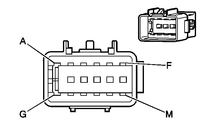
C313 Body Harness to the Passenger Seat Harness
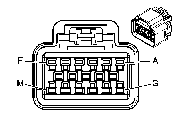
|
|
Connector Part Information
| Connector Part Information
|
Terminal Part Information
| Terminal Part Information
|
Pin | Wire Color | Circuit No. | Function | Pin | Wire Color | Circuit No. | Function |
|---|---|---|---|---|---|---|---|
A | D-BU | 2307 | Passenger Air Bag On Indicator Control | A | D-BU | 2307 | Passenger Air Bag On Indicator Control |
B | D-GN | 2308 | Passenger Air Bag Off Indicator Control | B | D-GN | 2308 | Passenger Air Bag Off Indicator Control |
C | -- | -- | Not Used | C | -- | -- | Not Used |
D | YE | 1139 | Ignition One Voltage | D | YE | 1139 | Ignition One Voltage |
E | -- | -- | Not Used | E | -- | -- | Not Used |
F | BK/WH | 2151 | Ground | F | BK/WH | 2151 | Ground |
G | RD | 1362 | Seat Belt Switch - Right - Signal | G | BK/WH | 2484 | Seat Belt Switch - Right - Signal |
H | BK | 407 | Low Reference | H | BK | 2644 | Low Reference |
J | L-BU | 5056 | Seat Position Sensor- Right - Signal | J | BK | 2645 | Seat Position Sensor- Right - Signal |
K | -- | -- | Not Used | K | -- | -- | Not Used |
L | TN/BK | 371 | Serial Data Link | L | PK | 2306 | Serial Data Link |
M | BK/WH | 2151 | Ground | M | BK/WH | 2151 | Ground |
C314 Body Harness to the Driver Seat Harness

|

|
Connector Part Information
| Connector Part Information
|
Terminal Part Information
| Terminal Part Information
|
Pin | Wire Color | Circuit No. | Function | Pin | Wire Color | Circuit No. | Function |
|---|---|---|---|---|---|---|---|
A | BK/WH | 238 | Ground | A | BK/WH | 238 | Ground (AG1) |
B | BK/WH | 407 | Seat Belt Switch - Left | B | BN/WH | 2151 | Seat Belt Switch - Left (AG1) |
C | L-GN | 5055 | Seat Position Switch - Left - Signal | C | L-GN | 2638 | Seat Position Switch - Left - Signal |
D | BK | 407 | Low Reference | D | TN | 2644 | Low Reference |
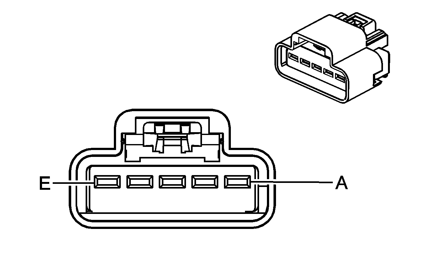
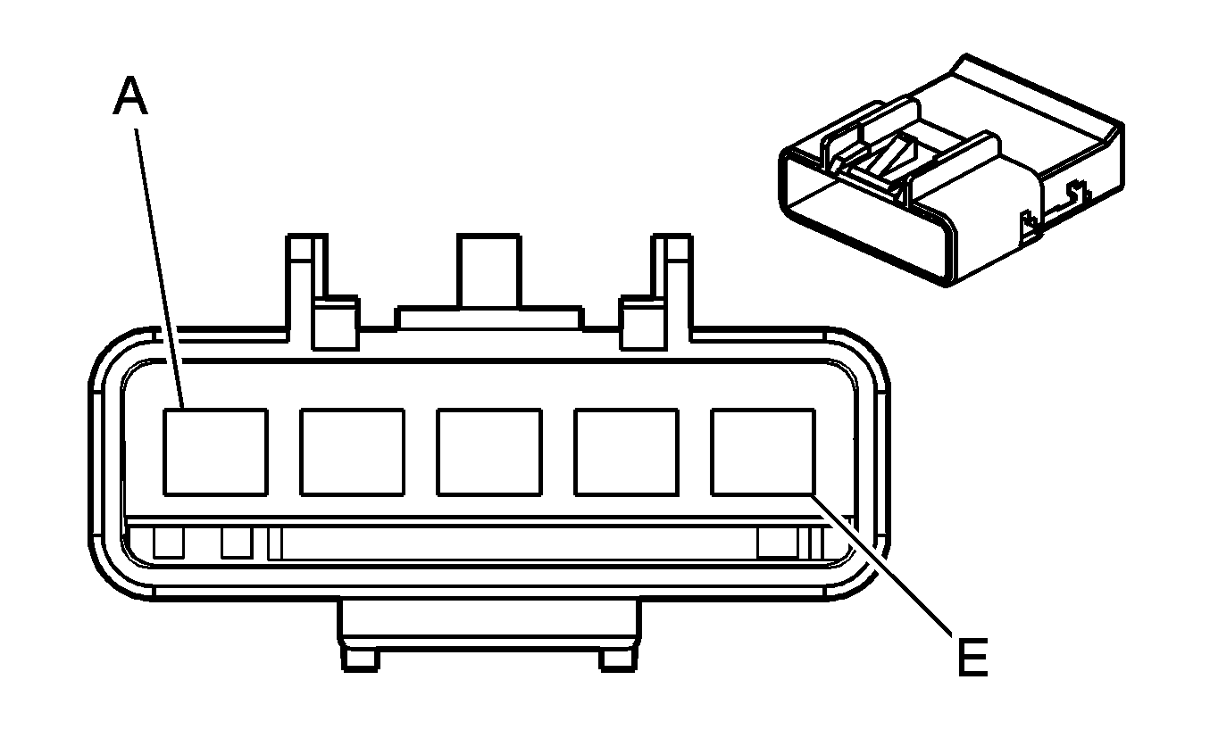
C315 Body Harness to the Passenger Seat Harness (AG2)
|
|
Connector Part Information
| Connector Part Information
|
Terminal Part Information
| Terminal Part Information
|
Pin | Wire Color | Circuit No. | Function | Pin | Wire Color | Circuit No. | Function |
|---|---|---|---|---|---|---|---|
A | BN | 141 | Ignition 3 Voltage | A | BN | 141 | Ignition 3 Voltage |
B | BK | 2050 | Ground | B | BK | 2050 | Ground |
C | RD | 1362 | Seat Belt Switch - Right | C | L-BU | 2179 | Seat Belt Switch - Right |
D | OG | 2240 | Battery Positive Voltage | D | OG | 2240 | Battery Positive Voltage |
E | OG | 1040 | Battery Positive Voltage | E | OG | 1040 | Battery Positive Voltage |
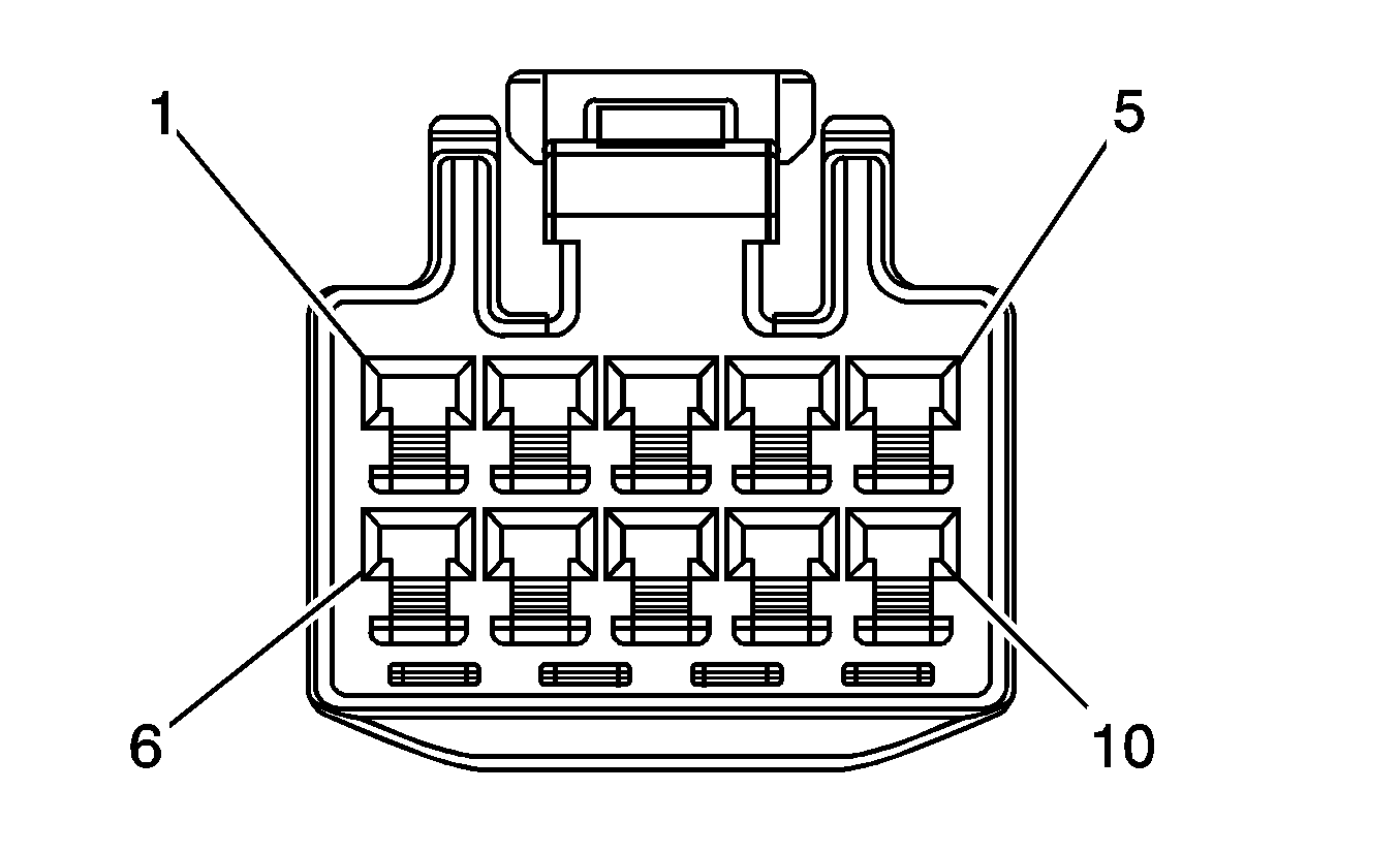
C316 Body Harness to the Left Rear Passenger Door Harness (Crew Cab w/A31)
|
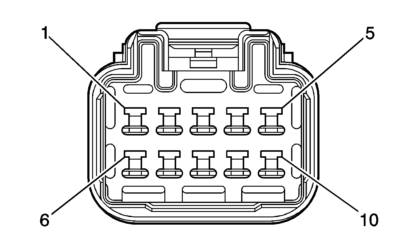
|
Connector Part Information
| Connector Part Information
|
Terminal Part Information
| Terminal Part Information
|
Pin | Wire Color | Circuit No. | Function | Pin | Wire Color | Circuit No. | Function |
|---|---|---|---|---|---|---|---|
1 | YE | 116 | Left Rear Speaker Output (-) | 1 | YE | 116 | Left Rear Speaker Output (-) |
2 | BN | 199 | Left Rear Speaker Output (+) | 2 | BN | 199 | Left Rear Speaker Output (+) |
3 | D-GN | 168 | Power Window Master Switch Left Rear Up Signal | 3 | D-GN | 168 | Power Window Master Switch Left Rear Up Signal |
4 | YE | 1187 | Power Window Master Switch Left Rear Down Signal | 4 | YE | 1187 | Power Window Master Switch Left Rear Down Signal |
5 | BN | 9 | Park Lamp Supply Voltage | 5 | BN | 9 | Park Lamp Supply Voltage |
6 | TN | 294 | Door Lock Actuator Unlock Control (AU3) | 6 | TN | 294 | Door Lock Actuator Unlock Control (AU3) |
7 | GY | 295 | Door Lock Actuator Lock Control (AU3) | 7 | GY | 295 | Door Lock Actuator Lock Control (AU3) |
8 | BK | 850 | Ground | 8 | BK | 850 | Ground |
9 | D-BU | 1307 | Power Window Master Switch Lockout Signal | 9 | D-BU | 1307 | Power Window Master Switch Lockout Signal |
10 | YE | 443 | Accessory Voltage | 10 | YE | 443 | Accessory Voltage |
C316 Body Harness to the Left Rear Passenger Door Harness (Crew Cab w/o A31)
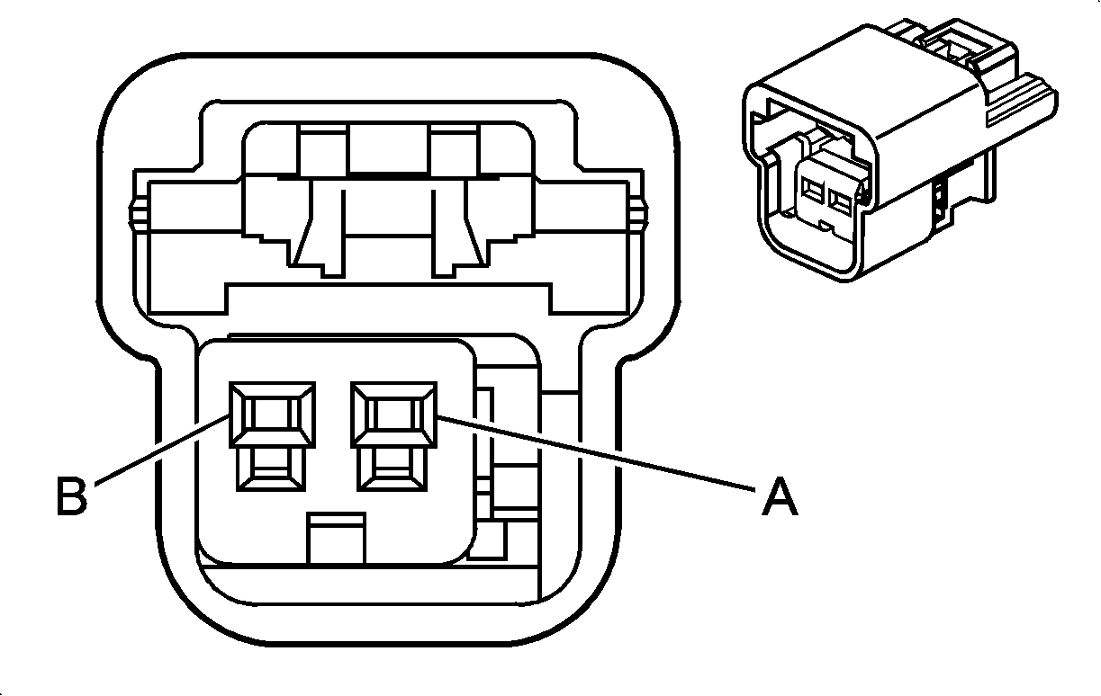
|
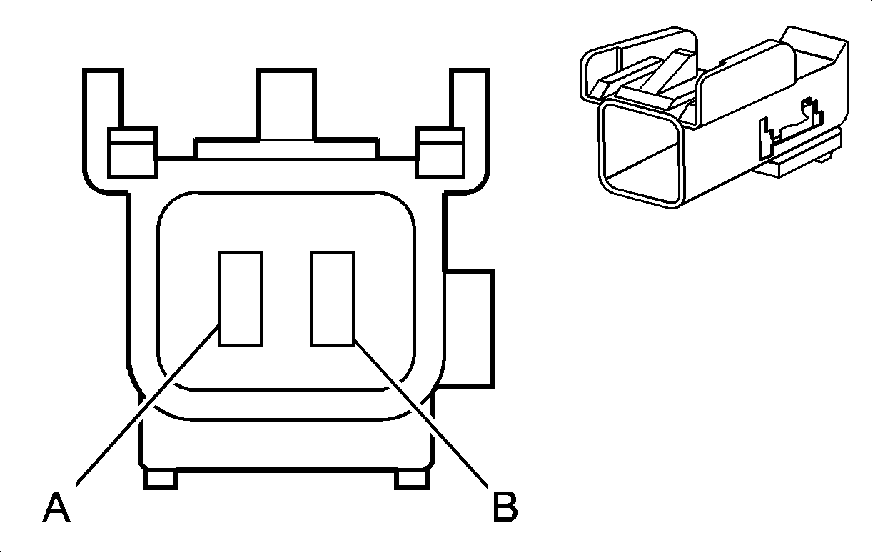
|
Connector Part Information
| Connector Part Information
|
Terminal Part Information
| Terminal Part Information
|
Pin | Wire Color | Circuit No. | Function | Pin | Wire Color | Circuit No. | Function |
|---|---|---|---|---|---|---|---|
A | YE | 116 | Left Rear Speaker Output (-) | A | YE | 116 | Left Rear Speaker Output (-) |
B | BN | 199 | Left Rear Speaker Output (+) | B | BN | 199 | Left Rear Speaker Output (+) |
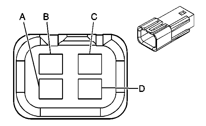
C316 Body Harness to the Left Rear Passenger Door Harness (Extended Cab)
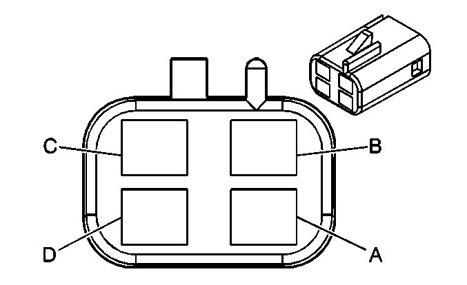
|
|
Connector Part Information
| Connector Part Information
|
Terminal Part Information
| Terminal Part Information
|
Pin | Wire Color | Circuit No. | Function | Pin | Wire Color | Circuit No. | Function |
|---|---|---|---|---|---|---|---|
A | YE | 116 | Left Rear Speaker Output (-) | A | YE | 116 | Left Rear Speaker Output (-) |
B | BN | 199 | Left Rear Speaker Output (+) | B | BN | 199 | Left Rear Speaker Output (+) |
C | GY/BK | 745 | Left Front Door Ajar Switch Signal | C | GY/BK | 745 | Left Front Door Ajar Switch Signal |
D | BK/WH | 1151 | Ground | D | BK/WH | 1151 | Ground |
C317 Body Harness to the Right Rear Passenger Door Harness (Crew Cab w/A31)

|

|
Connector Part Information
| Connector Part Information
|
Terminal Part Information
| Terminal Part Information
|
Pin | Wire Color | Circuit No. | Function | Pin | Wire Color | Circuit No. | Function |
|---|---|---|---|---|---|---|---|
1 | L-BU | 115 | Right Rear Speaker Output (-) | 1 | YE | 115 | Right Rear Speaker Output (-) |
2 | D-BU | 46 | Right Rear Speaker Output (+) | 2 | BN | 46 | Right Rear Speaker Output (+) |
3 | L-GN | 170 | Power Window Master Switch Right Rear Up Signal | 3 | D-GN | 168 | Power Window Master Switch Right Rear Up Signal |
4 | PU | 171 | Power Window Master Switch Right Rear Down Signal | 4 | YE | 1187 | Power Window Master Switch Left Rear Down Signal |
5 | BN | 9 | Park Lamp Supply Voltage | 5 | BN | 9 | Park Lamp Supply Voltage |
6 | TN | 294 | Door Lock Actuator Unlock Control | 6 | TN | 294 | Door Lock Actuator Unlock Control |
7 | GY | 295 | Door Lock Actuator Lock Control | 7 | GY | 295 | Door Lock Actuator Lock Control |
8 | BK | 2050 | Ground | 8 | BK | 850 | Ground |
9 | D-BU | 1307 | Power Window Master Switch Lockout Signal | 9 | D-BU | 1307 | Power Window Master Switch Lockout Signal |
10 | YE | 443 | Accessory Voltage | 10 | YE | 443 | Accessory Voltage |
C317 Body Harness to the Right Rear Passenger Door Harness (Crew Cab w/o A31)

|

|
Connector Part Information
| Connector Part Information
|
Terminal Part Information
| Terminal Part Information
|
Pin | Wire Color | Circuit No. | Function | Pin | Wire Color | Circuit No. | Function |
|---|---|---|---|---|---|---|---|
A | L-BU | 115 | Right Rear Speaker Output (-) | A | YE | 115 | Right Rear Speaker Output (-) |
B | D-BU | 46 | Right Rear Speaker Output (+) | B | BN | 46 | Right Rear Speaker Output (+) |
C317 Body Harness to the Right Rear Passenger Door Harness (Extended Cab)

|

|
Connector Part Information
| Connector Part Information
|
Terminal Part Information
| Terminal Part Information
|
Pin | Wire Color | Circuit No. | Function | Pin | Wire Color | Circuit No. | Function |
|---|---|---|---|---|---|---|---|
A | L-BU | 115 | Right Rear Speaker Output (-) | A | YE | 115 | Right Rear Speaker Output (-) |
B | D-BU | 46 | Right Rear Speaker Output (+) | B | BN | 46 | Right Rear Speaker Output (+) |
C | L-GN/BK | 748 | Right Front Door Ajar Switch Signal | C | GY/BK | 745 | Right Front Door Ajar Switch Signal |
D | BK/WH | 1251 | Ground | D | BK/WH | 1151 | Ground |
C318 Heat Element to Passenger Seat Harness (AG2)

|

|
Connector Part Information
| Connector Part Information
|
Terminal Part Information
| Terminal Part Information
|
Pin | Wire Color | Circuit No. | Function | Pin | Wire Color | Circuit No. | Function |
|---|---|---|---|---|---|---|---|
A | RD | -- | Battery Positive Voltage | A | OG | 2240 | Battery Positive Voltage |
B | BK | -- | Ground | B | BK | 2050 | Ground |
C | WH | -- | Passenger Heated Seat High/Low Signal | C | PK | 1501 | Passenger Heated Seat High/Low Signal |
D | -- | -- | Not Used | D | -- | -- | Not Used |
C319 Heat Element to Driver Seat Harness (AG1)

|

|
Connector Part Information
| Connector Part Information
|
Terminal Part Information
| Terminal Part Information
|
Pin | Wire Color | Circuit No. | Function | Pin | Wire Color | Circuit No. | Function |
|---|---|---|---|---|---|---|---|
A | RD | -- | Battery Positive Voltage | A | OG | 2240 | Battery Positive Voltage |
B | BK | -- | Ground | B | BK | 2050 | Ground |
C | WH | -- | Driver Heated Seat High/Low Signal | C | PK | 1501 | Driver Heated Seat High/Low Signal |
D | -- | -- | Not Used | D | -- | -- | Not Used |
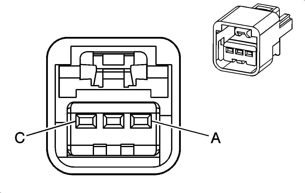
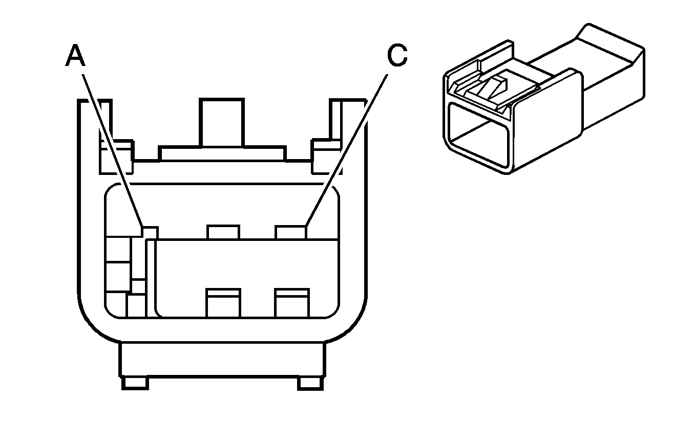
C320 Body Harness to Cargo Lamp/Center High Mounted Stop Lamp (CHMSL) Harness
|
|
Connector Part Information
| Connector Part Information
|
Terminal Part Information
| Terminal Part Information
|
Pin | Wire Color | Circuit No. | Function | Pin | Wire Color | Circuit No. | Function |
|---|---|---|---|---|---|---|---|
A | L-BU | 20 | Stop Lamp Supply Voltage | A | BN | 20 | Stop Lamp Supply Voltage |
B | GY/BK | 690 | Courtesy Lamp Supply Voltage (TR9) | B | WH | 690 | Courtesy Lamp Supply Voltage (TR9) |
C | BK | 850 | Ground | C | BK/WH | 850 | Ground |
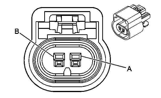
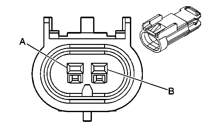
C400 Chassis Harness to the License Lamp Harness
|
|
Connector Part Information
| Connector Part Information
|
Terminal Part Information
| Terminal Part Information
|
Pin | Wire Color | Circuit No. | Function | Pin | Wire Color | Circuit No. | Function |
|---|---|---|---|---|---|---|---|
A | BN | 9 | Park Lamp Supply Voltage | A | BN | 9 | Park Lamp Supply Voltage |
B | BK | 850 | Ground | B | BK | 850 | Ground |
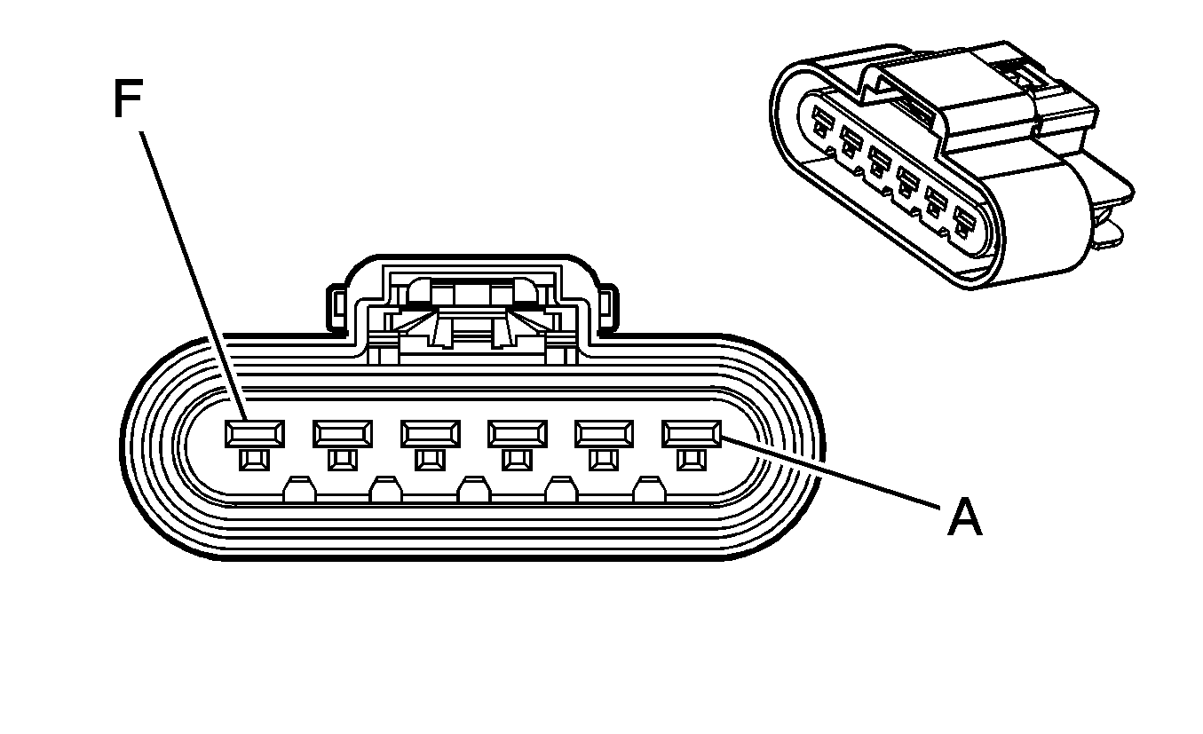
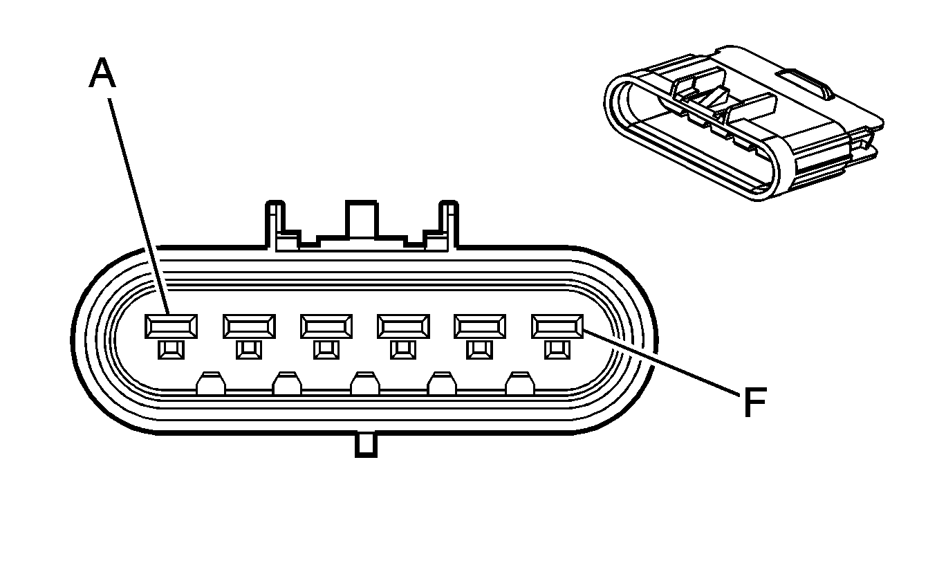
C401 Left Rear Lamp Assembly to the Chassis Harness (w/o Trailer Accessory)
|
|
Connector Part Information
| Connector Part Information
|
Terminal Part Information
| Terminal Part Information
|
Pin | Wire Color | Circuit No. | Function | Pin | Wire Color | Circuit No. | Function |
|---|---|---|---|---|---|---|---|
A | -- | -- | Not Used | A | D-GN | 19 | Right Rear Turn Signal Lamps Supply Voltage |
B | L-GN | -- | Backup Lamp Supply Voltage | B | L-GN | 24 | Backup Lamp Supply Voltage |
C | BN | -- | Park Lamp Supply Voltage | C | BN | 9 | Park Lamp Supply Voltage |
D | YE | -- | Left Rear Turn Signal Lamps Supply Voltage | D | YE | 18 | Left Rear Turn Signal Lamps Supply Voltage |
E | L-BU | -- | Stop Lamp Supply Voltage | E | L-BU | 20 | Stop Lamp Supply Voltage |
F | BK | -- | Ground | F | BK | 850 | Ground |
C401 Trailer Accessory Harness to the Chassis Harness (Trailer Accessory)

|

|
Connector Part Information
| Connector Part Information
|
Terminal Part Information
| Terminal Part Information
|
Pin | Wire Color | Circuit No. | Function | Pin | Wire Color | Circuit No. | Function |
|---|---|---|---|---|---|---|---|
A | GN | -- | Right Rear Turn Signal Lamps Supply Voltage | A | D-GN | 19 | Right Rear Turn Signal Lamps Supply Voltage |
B | BK | -- | Backup Lamp Supply Voltage | B | L-GN | 24 | Backup Lamp Supply Voltage |
C | BN | -- | Park Lamp Supply Voltage | C | BN | 9 | Park Lamp Supply Voltage |
D | YE | -- | Left Rear Turn Signal Lamps Supply Voltage | D | YE | 18 | Left Rear Turn Signal Lamps Supply Voltage |
E | BU | -- | Stop Lamp Supply Voltage | E | L-BU | 20 | Stop Lamp Supply Voltage |
F | WH | -- | Ground | F | BK | 850 | Ground |
C402 Right Rear Lamp Assembly to the Chassis Harness

|

|
Connector Part Information
| Connector Part Information
|
Terminal Part Information
| Terminal Part Information
|
Pin | Wire Color | Circuit No. | Function | Pin | Wire Color | Circuit No. | Function |
|---|---|---|---|---|---|---|---|
A | L-GN | -- | Backup Lamp Supply Voltage | A | L-GN | 24 | Backup Lamp Supply Voltage |
B | BN | -- | Park Lamp Supply Voltage | B | BN | 9 | Park Lamp Supply Voltage |
C | D-GN | -- | Right Rear Turn Signal Lamps Supply Voltage | C | D-GN | 19 | Right Rear Turn Signal Lamps Supply Voltage |
D | L-BU | -- | Stop Lamp Supply Voltage/Stop Lamp Switch Signal | D | L-BU | 20 | Stop Lamp Supply Voltage/Stop Lamp Switch Signal |
E | BK | -- | Ground | E | BK | 850 | Ground |
C403 Left Rear Lamp Assembly to the Trailer Accessory Harness (Trailer Accessory)

|

|
Connector Part Information
| Connector Part Information
|
Terminal Part Information
| Terminal Part Information
|
Pin | Wire Color | Circuit No. | Function | Pin | Wire Color | Circuit No. | Function |
|---|---|---|---|---|---|---|---|
A | -- | -- | Not Used | A | GN | -- | Right Rear Turn Signal Lamps Supply Voltage |
B | L-GN | -- | Backup Lamp Supply Voltage | B | BK | -- | Backup Lamp Supply Voltage |
C | BN | -- | Park Lamp Supply Voltage | C | BN | -- | Park Lamp Supply Voltage |
D | YE | -- | Left Rear Turn Signal Lamps Supply Voltage | D | YE | -- | Left Rear Turn Signal Lamps Supply Voltage |
E | L-BU | -- | Stop Lamp Supply Voltage | E | BU | -- | Stop Lamp Supply Voltage |
F | BK | -- | Ground | F | WH | -- | Ground |
