For 1990-2009 cars only
Tools Required
| • | J-44217-45 Chain Holding Tool |
| • | J 44217 Timing Chain Retention Tool |
| • | J 44221 Camshaft Holding Tool |
| • | J 45059 Angle Meter |
Removal Procedure
- Remove the camshaft cover. Refer to Camshaft Cover Replacement .
- Rotate the crankshaft in the engine rotational direction clockwise, until the #1 piston is at top dead center (TDC) on the compression stroke.
- Using the timing mark on the intake camshaft sprocket as a reference, make a mark on the timing chain link adjacent to it.
- Install the J 44221 to the rear of the camshafts.
- Complete the following in order to install the J 44217 (1) and J-44217-45 (1).
- Remove the intake camshaft sprocket bolt.
- Remove the intake camshaft sprocket.
- Clean and inspect the sprocket. Refer to Camshaft Timing Chain and Sprocket Cleaning and Inspection .
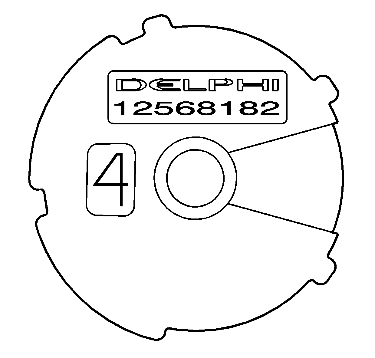
The word Delphi on the exhaust camshaft position actuator will be parallel with the cylinder head to cam cover mating surface.
Caution: Refer to Camshaft Holding Tool Caution in the Preface section.
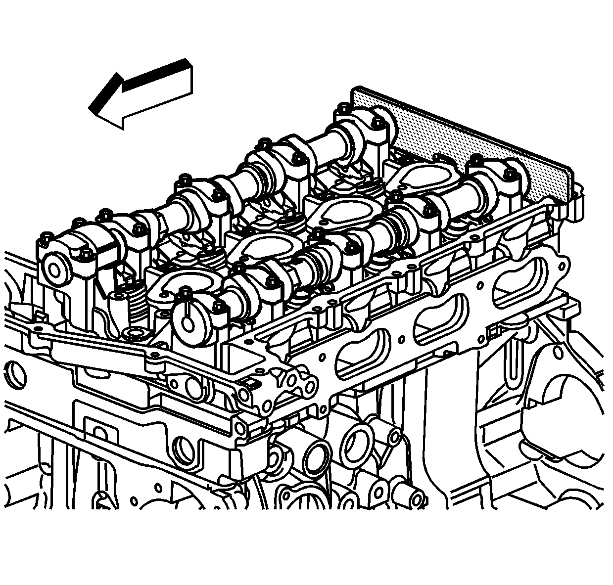
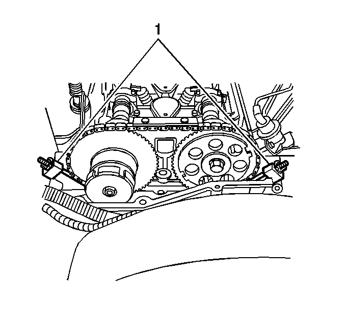
| 5.1. | Install the hook portion of the timing chain retention tools into one of the timing chain links near the timing chain shoe on both sides of the engine. |
| 5.2. | Tighten the wingnuts. |
| 5.3. | Ensure the hooks are still in one of the links and the gage blocks of the tool are firmly in place on the edge of the head. |
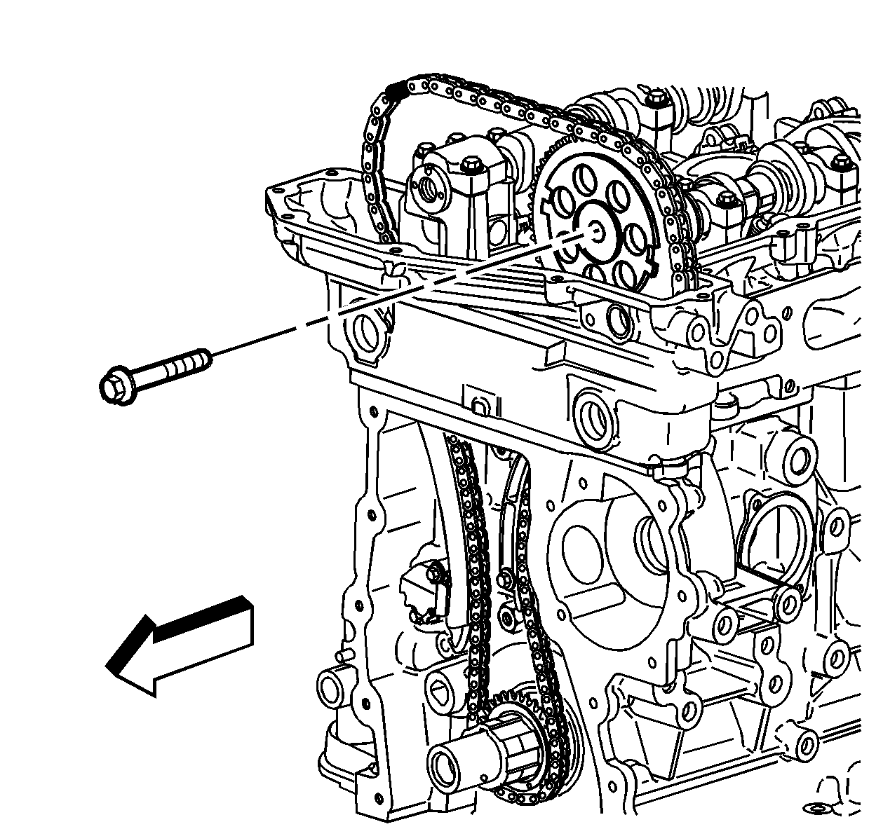
Discard the bolt.
Installation Procedure
- Install the intake camshaft sprocket into the timing chain.
- Install the intake camshaft sprocket onto the intake camshaft.
- Install the new intake camshaft sprocket bolt.
- Tighten the intake camshaft sprocket bolt to 20 N·m (15 lb ft).
- Use the J 45059 to rotate the intake camshaft sprocket bolt an additional 100 degrees.
- Remove the J 44217 (1) and J-44217-45 (1).
- Remove the J 44221 from the camshafts.
- Install the camshaft cover. Refer to Camshaft Cover Replacement .
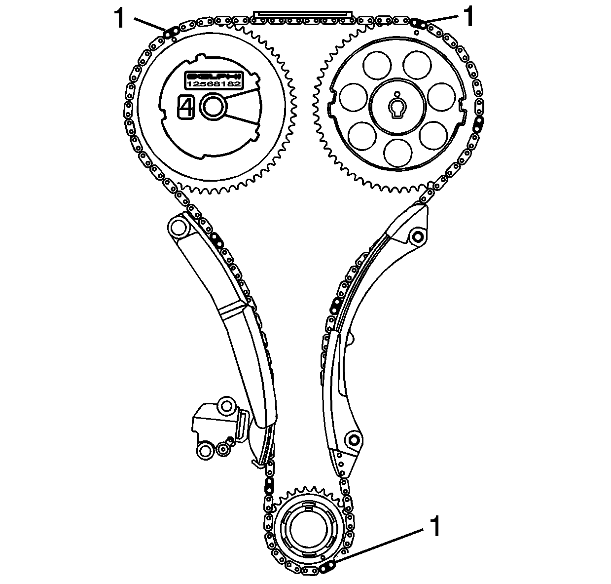
Aligning the marked link (1) on the timing chain with the timing mark on the intake camshaft sprocket.
Important:
• To aid in aligning the sprocket to the camshaft , use a 25 mm (1 in)
wrench on the hex of the camshaft to rotate • Ensure the alignment pin is properly engaged with the camshaft
Notice: Refer to Fastener Notice in the Preface section.
Tighten


