Information on New In-Vehicle Service Procedure for Removal/Installation of LK5 or L52 Cylinder Head

| Subject: | Information On New In-Vehicle Service Procedure for Removal/Installation of LK5 or L52 Cylinder Head |
| Models: | 2004-2006 Chevrolet Colorado |
| 2004-2006 GMC Canyon |
| 2006 HUMMER H3 |
| with Vortec™ 2.8L I-4, 3.5L I-5 Engine (VINs 8, 6 -- RPOs LK5, L52) |
This bulletin is being revised to change the Warranty Information. Please discard Corporate Bulletin Number 06-06-01-017D (Section 06 -- Engine/Propulsion System).
The following new service information outlined in this bulletin will aid technicians in removal and installation of the cylinder head without the removal of the front engine cover. The new service procedure can be done in-vehicle with the aid of a new General Motors special service tool part number EN-48464 - Lower Timing Gear Tensioner Holding Tool.
Important: If the Lower Timing Gear Tensioner Holding Tool is not wedged correctly, the front cover will have to be removed to reset the timing chain tensioner.
The Lower Timing Gear Tensioner Holding Tool will wedge between the timing chain tensioner and the front cover center bolt. When wedged in place, this will allow the camshafts or cylinder head to be serviced or removed without the removal of the front cover to reset the timing chain tensioner.
It is very important to make sure when timing the engine that all your timing marks align; there is no margin for error. If timed incorrectly, damage to the engine may occur or a DTC P0017 may set (PCM uses the crankshaft position (CKP) sensor and the exhaust camshaft position (CMP) sensor information to monitor the correlation between the crankshaft and camshaft positions).
Tools Required
The following tools will be required to perform this new service procedure outlined in this bulletin:
| • | EN-48464 - Lower Timing Gear Tensioner Holding Tool |
| • | EN-46547 - Flywheel Holding Tool (LK5 or L52 Engine Only) |
| • | J 44221 - Camshaft Holding Tool |
| • | J 45059 - Torque Angle Meter |
| • | TDC Indicator Tool (Some models may use a dial Indicator or graduation marks on the side of a sliding shaft for visual indication) |
SI Documents
Before starting this new service procedure outlined in this bulletin, refer to the following SI documents and review. Print the SI documents with an asterisk (*) next to the document . The asterisk indicates additional service information shown in this bulletin.
| • | Fuel Pressure Relief |
| • | Air Cleaner Resonator and Outlet Duct Replacement |
| • | Battery Replacement |
| • | Evaporative Emission Hoses/Pipes Replacement - Engine |
| • | Lifting and Jacking the Vehicle |
| • | Draining and Filling Cooling System (Static Fill) |
| • | Draining and Filling Cooling System (Vac-N-Fill) * |
| • | Wheelhouse Panel Replacement (Front) |
| • | Cylinder Head Replacement * |
| • | Cylinder Head Disassemble * |
| • | Engine Coolant Temperature Sensor Replacement * |
| • | Valve Rocker Arm and Valve Lash Adjusters |
| • | Intake Camshaft Position Sensor Installation * |
| • | Exhaust Camshaft Position Sensor Installation * |
| • | Water Outlet Installation * |
| • | Camshaft Position Actuator Solenoid Valve Installation * |
| • | Cylinder Head Cleaning and Inspection |
| • | Camshafts Cleaning and Inspection |
| • | Camshaft Installation * |
| • | Camshaft Cover Cleaning and Inspection |
| • | Exhaust Manifold Replacement * |
| • | Intake Manifold Replacement * |
| • | Tire and Wheel Removal and Installation * |
| • | Oil Pan Skid Plate Replacement * |
| • | Engine Shield Replacement * |
| • | Oil Level Indicator and Tube Replacement Removal Procedure * |
| • | Engine Lift Bracket Replacement * |
| • | Drive Belt Replacement * |
| • | Generator Replacement * |
| • | Capacities - Approximate Fluid * |
Engine Cylinder Head Removal
- Install protective covering to the front of the vehicle. This is to protect the grille from damage.
- Install fender covers.
- Bleed the fuel pressure. Refer to Fuel Pressure Relief in SI.
- Remove the air cleaner resonator, the outlet duct and the air cleaner assembly.
- Remove the battery from the vehicle. Refer to Battery Replacement in SI.
- Disconnect the Fuel/EVAP lines from the intake manifold and move aside (includes fuel line removal from fuel rail). Refer to Evaporative Emission Hoses/Pipes Replacement - Engine in SI.
- Remove the bolt holding the oil indicator (dipstick) tube to the intake manifold and move the oil dipstick aside (Do not remove).
- Drain the engine coolant. Refer to Draining and Filling Cooling System (Static Fill) in SI.
- Lift the Vehicle. Refer to Lifting and Jacking the Vehicle in SI.
- Remove the bolts holding the engine shield.
- Remove the engine shield from the vehicle.
- Remove the bolts holding the oil pan skid plate.
- Remove the oil pan skid plate from the vehicle.
- Remove the drive belt.
- Drain the engine oil.
- Remove left front tire and wheel.
- Remove the left front wheelhouse panel. Refer to Wheelhouse Panel Replacement (Front) in SI.
- Remove the fir tree wiring harness connectors from the engine wring harness bracket from the left front wheelhouse opening.
- Remove the intake manifold bolts from the wheelhouse access (bolts stay with intake manifold). On two-wheel drive vehicles, the intake manifold bolts are removed from the top of the engine, not through the left front wheelhouse panel.
- Lower the vehicle.
- Remove the PCV pipes from the cam cover and remove the intake manifold from the vehicle.
- Remove the generator output BAT terminal nut.
- Remove the generator lead from the generator.
- Disconnect the generator electrical connector.
- Remove the generator bolts and set the generator aside. The generator does not have to be removed from the vehicle. On a two-wheel drive vehicle, the generator must be removed from the vehicle.
- Disconnect the A/C pipe clamp from the engine lift hook bracket.
- Remove the engine lift hook bracket bolts and bracket from the vehicle.
- Remove the bolts holding the windshield washer solvent container and coolant recovery reservoir to the right inner fender. Move aside to gain access to the engine wiring harness to PCM.
- Disconnect the following cross-vehicle engine wiring harness connectors:
- Remove the A.I.R. injection pipe block-off plate bolts from the cylinder head.
- Remove the A.I.R. injection pipe block-off plate.
- Remove the bolts from the exhaust manifold heat shield.
- Remove the exhaust manifold heat shield.
- Remove the exhaust manifold bolts.
- Move the exhaust manifold back and away from the cylinder head.
- Remove the bolts to all ignition coil assemblies and remove all ignition coil assemblies from the cam cover.
- Remove all the spark plugs from the cylinder head.
- Remove the cam cover bolts.
- Remove the cam cover from the cylinder head.
- Remove the upper radiator hose and clamp from the cylinder head.
- Perform the following service timing procedure:
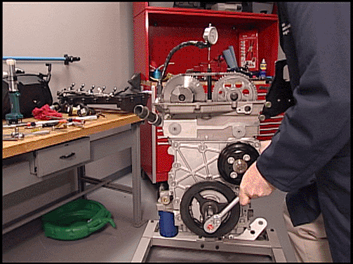
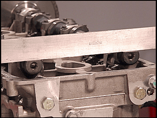
- Rotate the engine clockwise by hand to TDC on the compression stroke by using a piston TDC indicator tool and/or dial indicator in the number 1 cylinder. Refer to the above illustrations View A and View B . The TDC indicator tool graduation marks on the shaft should note top of the piston stroke. When the piston is at TDC, the flats at the rear of the camshafts will be facing up and flat when using a straight edge across the camshaft flats. There may be a variation of build and the straight edge may not lay perfectly flat across back of the camshafts. Refer to the above illustration VIEW C .
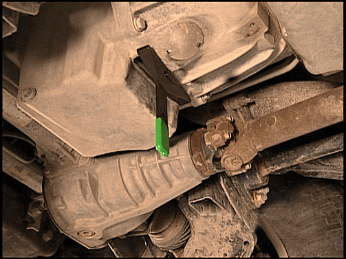
- Once TDC is located for the number 1 cylinder using above method, raise the vehicle and lock the flywheel with tool EN-46547 - Flywheel Holding Tool. Refer to the above illustration.
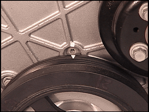
- Use a metal scribe, or equivalent, to place a reference mark on the harmonic balancer to the front cover for alignment purposes ( White Paint Pen is for demonstration purposes only). Refer to above illustration.
- Lower the vehicle.
- Install the J 44221 - Camshaft Holding Tool to the back of the camshafts. Refer to the above illustration.
- Remove the upper timing chain guide from the cylinder head (not found on later vehicles).
- Clean the timing chain and gears with Brake Cleaner or suitable solvent. Use a metal scribe or equivalent to place a reference mark on both timing gear sprockets and the timing chain to mark the location prior to disassembly. It is recommended that a metal scribe or equivalent be in the 12:00 position (White Paint Pen for demonstration purposes only). Refer to the above illustration.
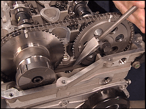
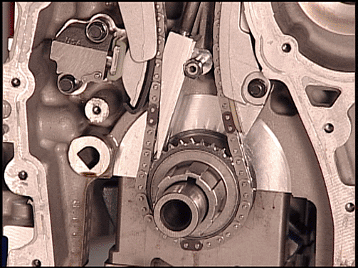
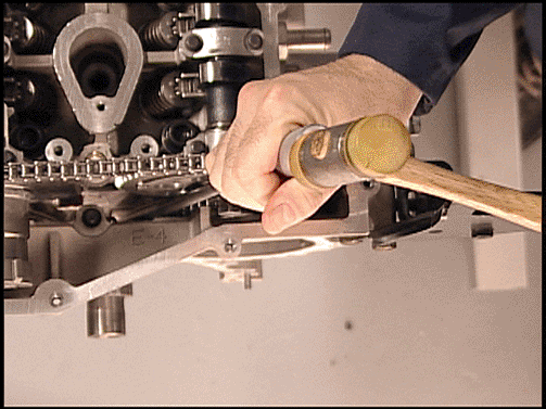
- Install EN-48464 - Lower Timing Chain Tensioner Holding Tool per the above illustration View A. This wedge tool will hold the timing chain and tensioner in position. It is important to install the tool with the proper orientation and to ensure that it is seated square against the timing chain and against the timing cover center bolt. The narrow ramp of the wedge tool needs to be placed so that it faces the timing chain. Refer to the above illustration View B. The wedge tool should be lightly seated using a couple of very light taps with a small plastic or brass hammer. Refer to the above illustration View C .
- Once the tool is correctly installed, unscrew the handle and remove the handle. Refer to the above illustration.
- Remove (1 long and 2 short ) cylinder head bolts next to the exhaust and intake timing chain tensioner shoes and discard the bolts.
- Remove both upper cylinder head access hole plugs from the front of the cylinder head.
- Remove both upper timing chain tensioner shoe bolts.
- Remove the exhaust and the intake camshaft sprocket bolts. Discard the bolts.
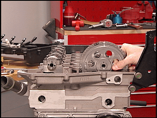
- Carefully remove the exhaust and intake camshaft sprockets from the exhaust and intake camshafts while still engaged with the timing chain. Refer to the above illustration. The above illustration shows the exhaust camshaft sprocket already removed.
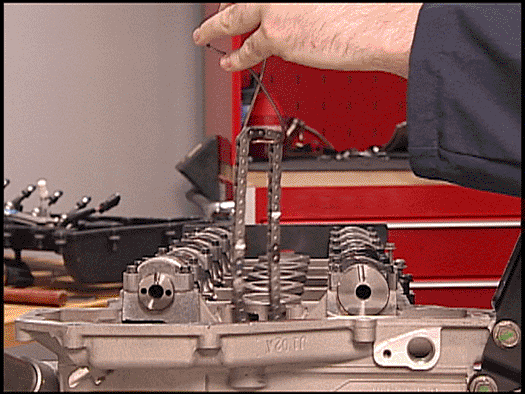
- Remove the sprockets from the chain. Tie a piece of mechanics wire on the timing chain and let it drop. Refer to the above illustration.
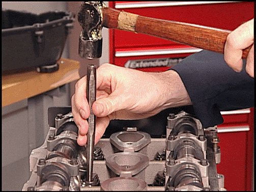
- Remove the cylinder head bolts from the cylinder head. Before removing the cylinder head bolts, use a drift punch and hammer to shock the bolts. This will ensure that the cylinder head bolts will not strip out the threads in the engine block or break. Once the bolts are removed, discard them. Refer to the above illustration.
- Remove the cylinder head from the vehicle.
- Disassemble the cylinder head. Refer to SI for the following cylinder head procedures:
| • | Refer to Air Cleaner Resonator and Outlet Duct Replacement Removal Procedure in SI. |
| • | Refer to Air Cleaner Assembly Replacement in SI. |
| • | PCM |
| • | Engine Coolant Temperature Sensor |
| • | MAP Sensor |
| • | Ignition Coils |
| • | Harness clamps at power steering pump |
| • | Wiring Harness fastener at right front inner fender |
| • | Throttle Body |
| • | Camshaft Sensors |
| • | Exhaust Camshaft Actuator |
| • | Fuel Injectors |
| • | HO2S #1 |
| • | Set aside the cross-vehicle engine wiring harness on the left side of the vehicle. |
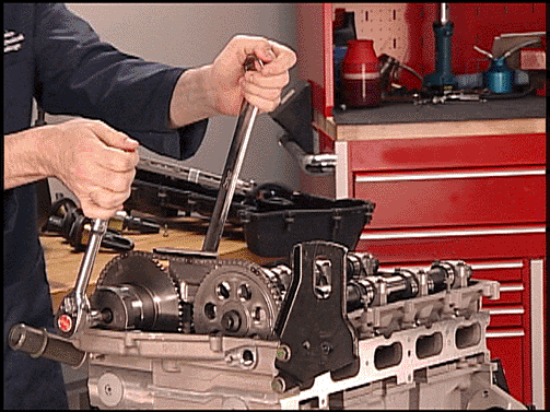
Important: Before performing the TDC procedures, break loose both the exhaust and intake camshaft sprocket bolts. Use a 25 mm (1 in) open end wrench on the camshaft hexs to hold the camshaft from turning. Do Not remove the bolts. Refer to the above illustration.
View A
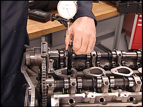
View B
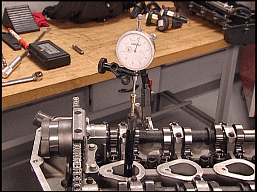
View C
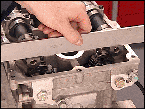
Important: Do not rotate the engine counterclockwise to find TDC, as this will put slack in the camshaft actuator and the timing chain. If the engine is rotated counterclockwise, even a small amount, then the engine should be rotated at least 90 degrees and then brought back to TDC by rotating clockwise only.
Important: The word Delphi on the exhaust camshaft position actuator will be parallel with the cylinder head to cam cover mating surface. When the piston is at TDC, the flats at the rear of the camshafts will be facing up.
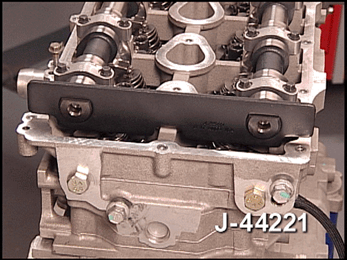
Camshaft Holding Tool Caution: The camshaft holding tools must be installed on the camshafts to prevent camshaft rotation. When performing service to the valve train and/or timing components, valve spring pressure can cause the camshafts to rotate unexpectedly and can cause personal injury.
Important: If the timing is correct (TDC compression stroke number 1 cylinder), the camshaft flats will be in the up position.
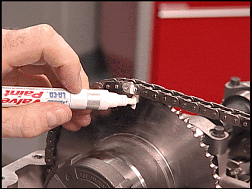
Important: The exhaust camshaft actuator must be fully advanced before scribing your reference mark on both timing gear sprockets and the timing chain to mark location prior to disassembly. There may be some normal play in the exhaust camshaft actuator itself. To ensure camshaft actuator is fully advanced, do not rotate engine counterclockwise when finding TDC #1.
View A
View B
View C
Important: Illustration View B shows the front cover removed for demonstration purposes only.
Important: Refer to PIP3940B, a supplement to this bulletin, user tips for EN48464-Lower Timing Chain Tensioner Holding Tool .
Notice: Do NOT use excessive force to seat the wedge tool. If excessive force is used, you may damage the timing chain tensioner or break the front cover bolt requiring complete disassembly of the front engine.
Important: The illustration below shows the front cover removed for demonstration purposes only.
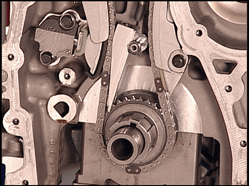
Important: Use a 25 mm (1 in) open end wrench on the camshaft hexs to hold the camshaft from turning. It is critical that the crankshaft does not move and is held at TDC when the intake and exhaust camshaft sprocket bolts are removed.
Important: If the crankshaft is not held in place, the wedge tool could be dislodged. If the crankshaft moves, or if the tool is not seated properly allowing the timing chain tensioner to extend, the repair will have to be completed by removing the front cover to release the timing chain tensioner.
Important: Refer to Service Bulletin 05-06-01-026A for additional information on Torque to Yield Bolt Breakage.
| • | Cylinder Head Disassemble - The following components will have to be removed when disassembling the cylinder head. Refer to SI for the following service procedures: |
| - | Engine Coolant Temperature Sensor Replacement |
| - | Intake Camshaft Position Sensor Removal / Installation |
| - | Exhaust Camshaft Sensor Removal / Installation |
| - | Camshaft Position Actuator Solenoid Valve Removal / Installation |
| - | Water Outlet Removal / Installation |
| - | Valve Rocker Arm and Valve Lash Adjusters Removal / Installation |
| • | Cylinder Head Cleaning and Inspection |
| • | Cylinder Head Assembly. Refer to the above service procedure for assembly. |
Engine Cylinder Head Installation
- Install the engine cylinder head to the engine block.
- Install new cylinder head bolts and tighten the bolts. Refer to Cylinder Head Replacement in SI.
- Install the camshafts with the flats up using the J 44221 - Camshaft Holding Tool . Refer to Camshaft Installation in SI.
- Install the exhaust camshaft actuator/sprocket and chain onto the exhaust camshaft. Use scribe marks as an alignment guide.
- Install the intake camshaft sprocket and chain onto the intake camshaft. Use scribe marks as alignment guide.
- Tighten the new intake camshaft sprocket bolt. Refer to the above illustration.
- Tighten the new exhaust camshaft actuator sprocket bolt. Refer to the above illustration.
- Install both upper timing chain tensioner shoe bolts.
- Install both upper cylinder head access hole plugs to the front of the cylinder head.
- Lift the vehicle and remove the EN-46547 - Flywheel Holding Tool. Refer to the above illustration.
- Lower the vehicle.
- Remove the J 44221 - Camshaft Holding Tool from the back of the camshafts. Refer to the above illustration.
- Install the handle of the EN-48464 - Lower Timing Chain Tensioner Holding Tool and remove the wedge portion of the tool from the engine. Refer to the above illustration.
- Rotate the engine clockwise by hand two complete revolutions to TDC #1 on the compression stroke. Refer back to step number 41 (Perform the following Service Timing Procedure) in this bulletin. If you go past TDC, rotate the engine back approximately 45 degrees before TDC and then rotate clockwise up to TDC to ensure that the timing chain is tight (no slack) between the crank sprocket and the timing gears. Refer to the above illustration.
- Both intake and exhaust camshaft flats should be facing up and flat with the cylinder head. If the J 44221 - Camshaft Holding Tool is used to verify cam timing, you could be off approximately one tooth and cause DTC P0017 to set. Refer to the above illustration View A . Refer to the above illustration View B (1) showing worn out Camshaft Holding Tool and call out (2) showing a new Camshaft Holding Tool. If a worn or new J 44221 - Camshaft Holding Tool is used to verify timing, the timing will be off.
- To verify timing, set a straight edge across the flats of the camshafts. Refer to the above illustration View A . Both camshaft flats should be flat. there may be some variation of build and the straight edge may not lay perfectly flat across back of the camshafts. If one or both camshaft flats are off, then the timing is off. Refer to the above illustration View A (1). Repeat step procedure 15 and recheck. If the camshaft flats are still not flat, the camshaft timing will have to be reset. This may require removal and reinstallation of one or both camshaft sprockets. Refer to step #46 in this bulletin.
- Install (1 long and 2 short ) cylinder head bolts next to the exhaust and intake timing chain tensioner shoes and tighten the bolts. Refer to Cylinder Head Replacement in SI.
- Position the upper timing chain guide to the cylinder head. Apply threadlocker (Red High Strength) adhesive, P/N 89021297 (in Canada, use 10953488), to the upper timing chain guide bolt threads.
- Install the upper timing chain guide bolts.
- Install the upper radiator hose and clamp to the cylinder head.
- Clean and inspect the camshaft cover. Refer to Camshaft Cover Cleaning and Inspection in SI.
- Install a NEW camshaft cover seal and NEW ignition control module seals to the cam cover. Position the camshaft cover to the cylinder head.
- Install the camshaft cover bolts.
- Check the gap on all of the spark plugs. The gap should be 1.08 mm (0.042 in). Tighten all of the spark plugs.
- Install the ignition coils into the camshaft cover.
- Install the ignition coil bolts.
- Reposition the exhaust manifold to the cylinder head and install the exhaust manifold bolts to the cylinder head. Refer to Exhaust Manifold Replacement in SI.
- Install a NEW A.I.R. injection gasket, then the cover and pipe studs to the cylinder head.
- Install the exhaust manifold heat shield to the exhaust manifold.
- Apply anti-seize, P/N 12371386 (in Canada, 89021945) to the exhaust manifold heat shield nuts
- Install the exhaust manifold heat shield nuts.
- Install the intake manifold to the cylinder head. Refer to Intake Manifold Replacement in SI. Raise the vehicle and install the blind intake manifold bolts from the left front wheelhouse access.
- Reposition the engine wiring harness bracket to the engine and harnesses. Install the engine wiring harness bracket bolts.
- Install the left front wheelhouse panel. Refer to Wheelhouse Panel Replacement (Front) in SI.
- Install the left wheel and tire. Refer to Tire and Wheel Removal and Installation in SI.
- Refill the engine oil. Refer to Capacities - Approximate Fluid in SI.
- Install the lower radiator hose if removed.
- Install the oil pan skid plate. Refer to Oil Pan Skid Plate Replacement in SI.
- Install the engine shield. Refer to Engine Shield Replacement in SI.
- Lower the vehicle.
- Install the cross-vehicle wiring harness connectors to the following components:
- Install the windshield washer solvent container and coolant recovery reservoir bolts to the right inner fender.
- Install the PCV pipes to the intake manifold. Refer to Crankcase Ventilation Hoses/Pipes Replacement in SI.
- Reposition the oil indicator (dipstick) tube and tighten the bolt to the intake manifold. Refer to Oil Level Indicator and Tube Replacement Removal Procedure in SI.
- Reposition the Fuel/ EVAP lines to the intake manifold retainer. Refer to Evaporative Emission Hoses/Pipes Replacement - Engine in SI.
- Install the following components. For installation and bolt tightening procedures, refer to the following SI documents.
- Install the battery. Refer to Battery Replacement in SI.
- Install the air induction assembly. Refer to Air Cleaner Resonator and Outlet Duct Replacement in SI.
- Refill with NEW engine oil. Refer to Capacities - Approximate Fluid in SI.
- Refill with NEW coolant. Refer to Draining and Filling Cooling System (Vac-N-Fill) in SI.
- Install the air cleaner resonator, the outlet duct and the air cleaner assembly.
- Remove the fender covers.
- Remove the protective covering from the front of the vehicle.
- Install the scan tool and start the engine.
Important: A new service cylinder head assembly with valves is available for L52 only.
Important: Install the cylinder head without the camshafts.

Camshaft Holding Tool Caution: The camshaft holding tools must be installed on the camshafts to prevent camshaft rotation. When performing service to the valve train and/or timing components, valve spring pressure can cause the camshafts to rotate unexpectedly and can cause personal injury.
Important: Before installing the camshafts, refer to Camshafts Cleaning and Inspection in SI.
Notice: Tension must be always kept on the intake side of the timing chain to properly keep the engine in time. If the chain is loose the timing will be off, which may cause internal engine damage or set DTC P0017.
Fastener Notice: Use the correct fastener in the correct location. Replacement fasteners must be the correct part number for that application. Fasteners requiring replacement or fasteners requiring the use of thread locking compound or sealant are identified in the service procedure. Do not use paints, lubricants, or corrosion inhibitors on fasteners or fastener joint surfaces unless specified. These coatings affect fastener torque and joint clamping force and may damage the fastener. Use the correct tightening sequence and specifications when installing fasteners in order to avoid damage to parts and systems.
Exhaust Camshaft Actuator Notice: The exhaust camshaft actuator must be fully advanced during installation. Engine damage may occur if the camshaft actuator is not fully advanced. Refer to Camshaft Position Actuator Diagnosis in SI.
Important: To aid in aligning the actuator to the camshaft, use a 25 mm (1 in) open end wrench on the hex of the camshaft to rotate. This will ensure the alignment pin is properly engaged with the camshaft and Hand Tighten the new exhaust camshaft sprocket bolt.
Important: To aid in aligning the intake sprocket to the camshaft, use a 25 mm (1 in) open end wrench on the hex of the camshaft to rotate. This will ensure the alignment pin is properly engaged with the camshaft and Hand Tighten the new intake camshaft sprocket bolt.
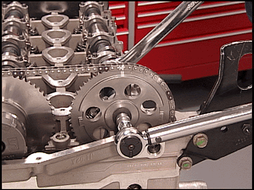
Tighten
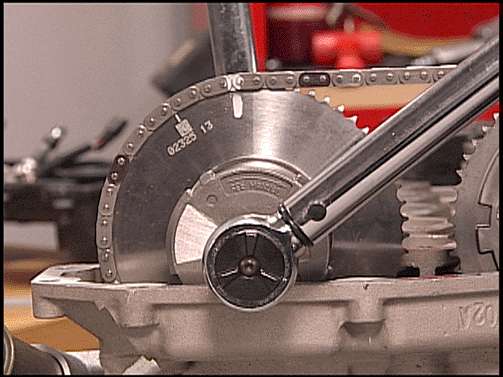
Tighten the intake camshaft sprocket bolt to 20 N·m (15 lb ft).
Torque Angle Meter
Use the J 45059 - Torque Angle Meter to rotate the intake camshaft sprocket bolt an additional 100 degrees.
Tighten
Tighten the exhaust camshaft actuator sprocket bolt to 25 N·m (18 lb ft).
Torque Angle Meter
Use the J 45059 - Torque Angle Meter to rotate the exhaust camshaft actuator sprocket bolt an additional 135 degrees.
Tighten
Tighten the tensioner shoe bolts to 25 N·m (18 lb ft).
Tighten
Tighten the plugs to 5 N·m (44 lb in).


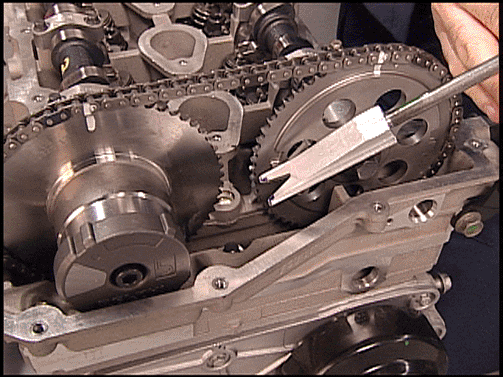
Notice: Ensure that the wedge tool is removed from the engine prior to rotation. If the wedge tool is not removed, engine damage will result.
Important: It is critical that the engine is at TDC and not a couple of degrees off. If in doubt, repeat this step.
View A

View B
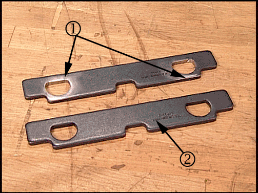
Important: Do Not use the J 44221 - Camshaft Holding Tool , installed to the back of the camshafts, as a method to verify timing.
View A
Tighten
Tighten the bolts to 10 N·m (89 lb in).
Tighten
Tighten the bolts to 10 N·m (89 lb in).
Tighten
Tighten the spark plugs to 18 N·m (13 lb ft).
Tighten
Tighten the bolts to 10 N·m (89 lb in).
Tighten
Tighten the pipe studs to 25 N·m (18 lb ft).
Tighten
Tighten the nuts to 10 N·m (89 lb in).
Tighten
Tighten the bracket bolts to 10 N·m (89 lb in).
| • | PCM |
| • | Map Sensor |
| • | Ignition Coils |
| • | Harness clamps at power steering pump |
| • | Wiring harness fastener at right front inner fender |
| • | Throttle Body |
| • | Camshaft Sensors |
| • | Exhaust Camshaft Actuator |
| • | Fuel Injectors |
| • | HO2S #1 |
Tighten
Tighten the bolts to 10 N·m (89 lb in).
| • | P/S pump bolts - Refer to Power Steering Pump Replacement in SI. |
| • | Generator - For further installation information, refer to Generator Replacement in SI. |
| • | A/C compressor hose/pipe bracket clamp for the engine lift bracket - Refer to Engine Lift Bracket Replacement in SI. |
| • | Drive Belt - For further installation information, refer to Drive Belt Replacement in SI. |
| • | Refer to Air Cleaner Resonator and Outlet Duct Replacement Removal Procedure in SI. |
| • | Refer to Air Cleaner Assembly Replacement in SI. |
| • | Check for DTCs. |
| • | Road test the vehicle. DTC P0017 is a Type B diagnostic code. Three consecutive ignition key cycles must be performed during the road test with a minimum of a one minute run time between key cycles to verify that a DTC P0017 did not set. For further information on DTC P0017, refer to SI. |
Parts Information 2.8L I-4 LK5 Engine
Part Number | Description | Qty |
|---|---|---|
88984230 | Head ASM, CYL | 1 |
24576975 | Exhaust - Valve | 8 |
24576974 | Intake - Valve | 8 |
12596994 | Seal, Engine Valve | 16 |
88984220 | Gasket, Kit (includes Cyl HD, EXH and INT Manifolds, Cam Cover, Secd Air) | 1 |
88958974 | Seal, IGN Coil (1 PCS) | 4 |
11519306 | Bolt, CYL HD | 1 |
11519038 | Bolt, CYL HD | 2 |
12568079 | Bolt, CYL HD (With Captured Washer) | 10 |
12565425 | Bolt, CM/SHF SPKT | 1 |
24100263 | Bolt, CM/SHF POSN ACTR | 1 |
89021297 (in Canada, 10953488) | Adhesive (Red High Strength) | 1 |
12371386 (in Canada, 89021945) | Lubricant, Anti-Seize | 1 |
Parts Information 3.5L I-5 L52 Engine
Part Number | Description | Qty |
|---|---|---|
19168846 | Cylinder Head with Valves | 1 |
88984219 | Gasket, Kit (Includes CYL HD, EXH and INT Manifolds, Cam Cover, SECD AIR, IGN Coil Seals) | 1 |
11519306 | Bolt, CYL HD | 1 |
11519038 | Bolt, CYL HD | 2 |
12568079 | Bolt, CYL HD (With Captured Washer) | 12 |
12565425 | Bolt, CM/SHF SPKT | 1 |
24100263 | Bolt, CM/SHF POSN ACTR | 1 |
89021297 (in Canada, 10953488) | Adhesive (Red High Strength) | 1 |
12371386 (in Canada, 89021945) | Lubricant, Anti-Seize | 1 |
Warranty Information
For vehicles repaired under warranty, use:
Labor Operation | Description | Labor Time |
|---|---|---|
J0528 | Head, Cylinder with add times for valve replacement - Replace (2.8L I-4 LK5 Engine) | 5.8 hr + 0.9 Add = 6.7 hrs |
J0518 | Head, Cylinder with Valves Assembly - Replace (3.5L I-5 L52 Engine) | 6.2 hrs |
