For 1990-2009 cars only
Removal Procedure
- Raise and support the vehicle. Refer to Lifting and Jacking the Vehicle .
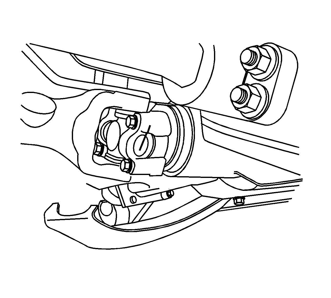
- Mark the front U-joint to the pinion yoke on the front differential.
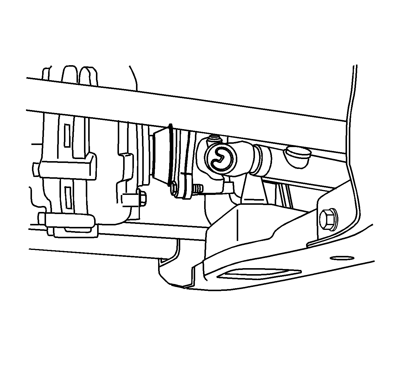
- Mark the relationship of the rear U-joint to the transfer case drive flange.
- Mark the relationship of the rear U-joint to the transfer case drive flange.
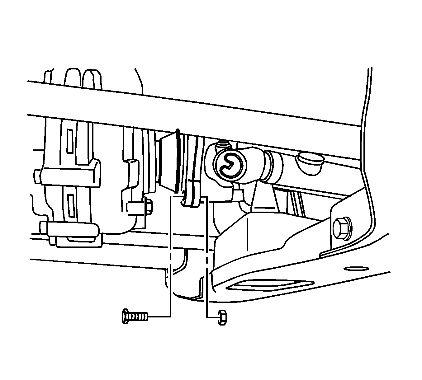
- Remove the retaining nuts and bolts from the drive flange.
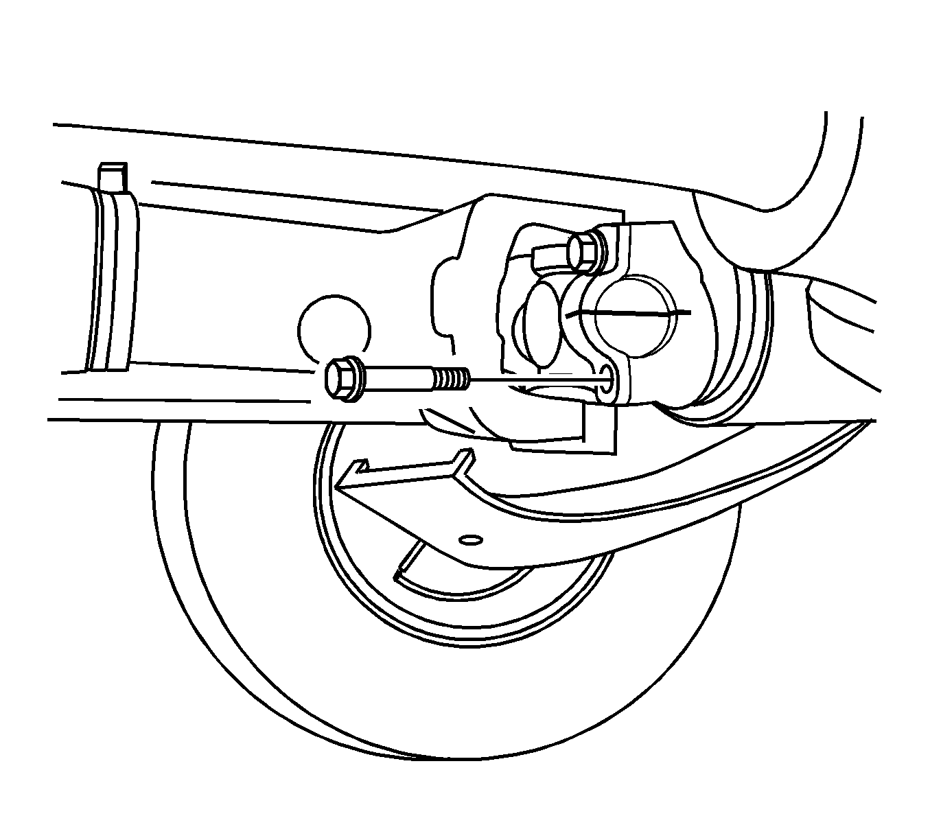
- Remove the clamps and retaining bolts from the front drive axle pinion flange.
- Remove the front propeller shaft from the vehicle.
- Using tape and or a rubber band, wrap the front U-joint bearing caps to ensure the caps do not separate from the U-joint.
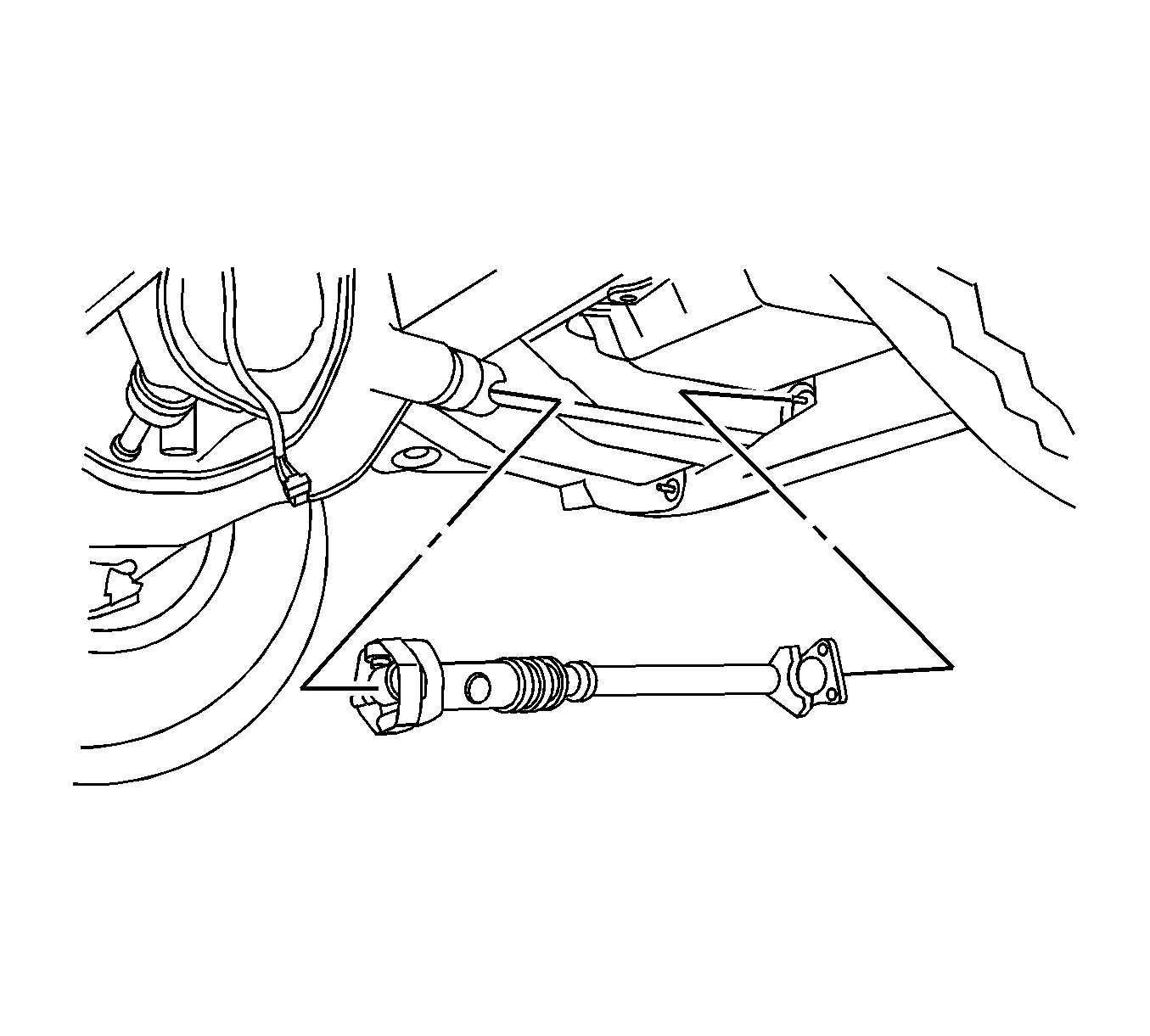
Installation Procedure.
- Remove the tape or rubber band from the front U-joint
- Install the front propeller shaft.
- Align the reference marks on the front U-joint.
- Install the front U-joint bolts and clamps.
- Align the reference marks on the rear U-joint.
- Install the propeller shaft to pinion flange bolts.
- Lower the vehicle.


Important: When installing the retaining bolts, only tighten them finger tight to hold the front propeller shaft in position.

Notice: Refer to Fastener Notice in the Preface section.

Tighten
| • | Tighten the bolts from the propeller shaft to the pinion flange 20 N·m (15 lb ft). |
| • | Tighten the bolts for the front propeller U-joint clamps 20 N·m (15 lb ft). |
