Front Case Half
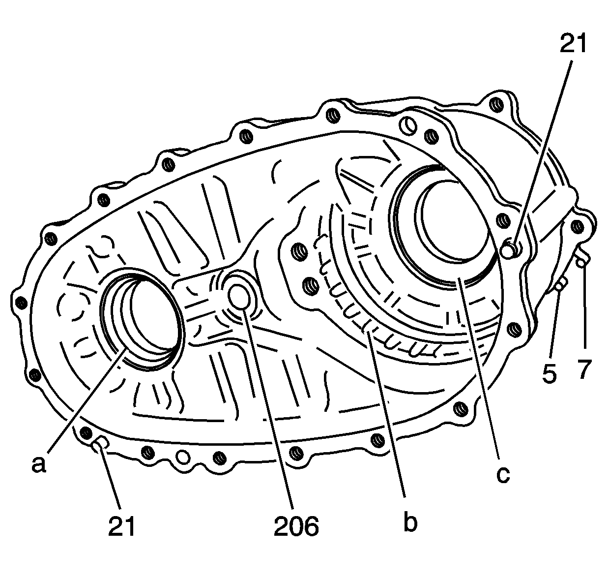
- Clean the front case half in cleaning solvent
and air dry.
Notice: Refer to Machined Surface Damage Notice in the Preface section.
- Remove the sealer from the case sealing surfaces.
- Inspect the case for being broken or cracked.
- Inspect the front output shaft front bearing bore (a) for the following
conditions:
- Inspect the planetary carrier bearing bore (c) for the following
conditions:
- Inspect the case annulus gear notches (b) for wear.
- Replace the front case half if any of the above conditions are found.
- Inspect the sealing surfaces for damage.
- Repair small scratches or nicks with a soft stone.
- Inspect the front case to transmission case mounting surface for damage.
- Inspect the case threaded bolt holes for damage.
- Repair any damaged threads.
- Inspect the location pins (21) for being loose or missing.
- Repair or replace any damaged location pins.
- Inspect the breather pipe and vent hose pipes (5 and 7)
for damage or leaking.
- Replace the pipes if faulty. Refer to
Transfer Case Disassemble
and
Transfer Case Assemble
.
- Inspect the control actuator shaft bushing (206) for excessive
wear.
- Replace the control actuator shaft bushing if faulty. Refer to
Transfer Case Disassemble
and
Transfer Case Assemble
.
- Inspect the front output shaft front bearing for the following conditions:
- Replace the bearing if any of the above conditions are found. Refer to
Transfer Case Disassemble
and
Transfer Case Assemble
.
Rear Case Half
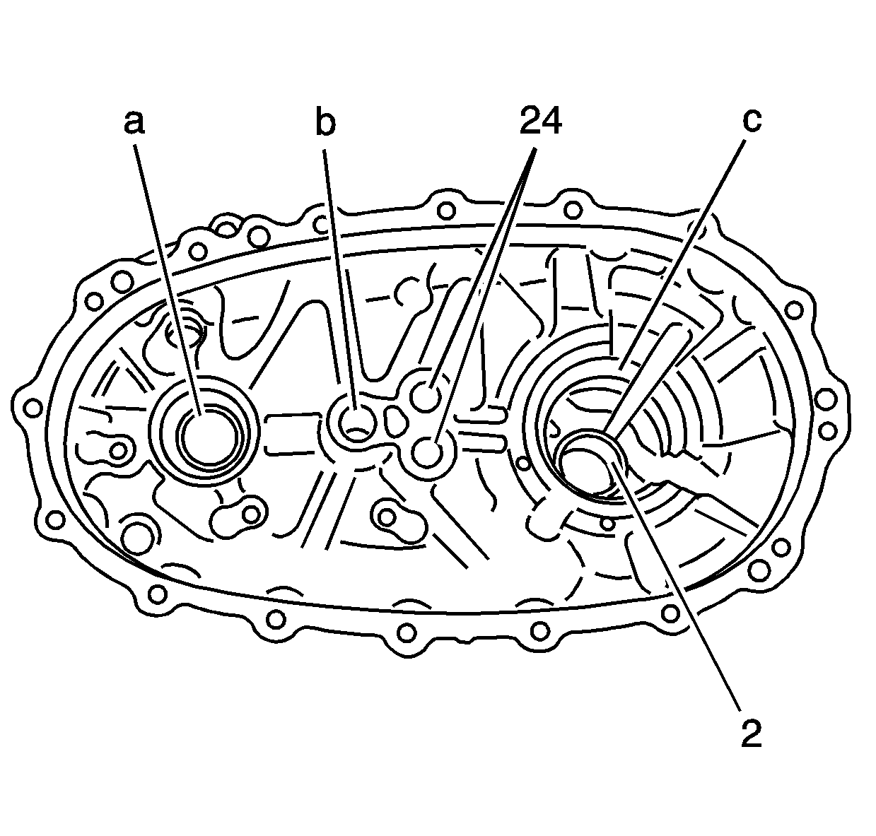
- Clean the rear case half in cleaning solvent
and air dry.
Notice: Refer to Machined Surface Damage Notice in the Preface section.
- Remove the sealer from the case sealing surfaces.
- Inspect the case for being broken or cracked.
- Replace the case if it is broken or cracked.
- Inspect the sealing surfaces for damage.
- Repair small scratches or nicks with a soft stone.
- Inspect the case threaded bolt holes for damage.
- Repair any damaged threads.
- Inspect the front output shaft rear bearing bore (a) for the following
conditions:
- Inspect the rear output shaft rear bearing bore (c) for the following
conditions:
- Replace the case if the bearing bores are faulty. Refer to
Transfer Case Disassemble
and
Transfer Case Assemble
.
- Inspect the rear output shaft bushing (2) for scoring or wear.
- Replace the bushing if faulty. Refer to
Transfer Case Disassemble
and
Transfer Case Assemble
.
- Inspect the control actuator shaft bore (b) for the following
conditions:
- Replace the case if the control actuator shaft bore is faulty. Refer to
Transfer Case Disassemble
and
Transfer Case Assemble
.
- Inspect the shift shaft plugs (24) for being loose or leaking.
- Replace the shift shaft plugs if leaking. Refer to
Transfer Case Disassemble
and
Transfer Case Assemble
.
Oil Pump
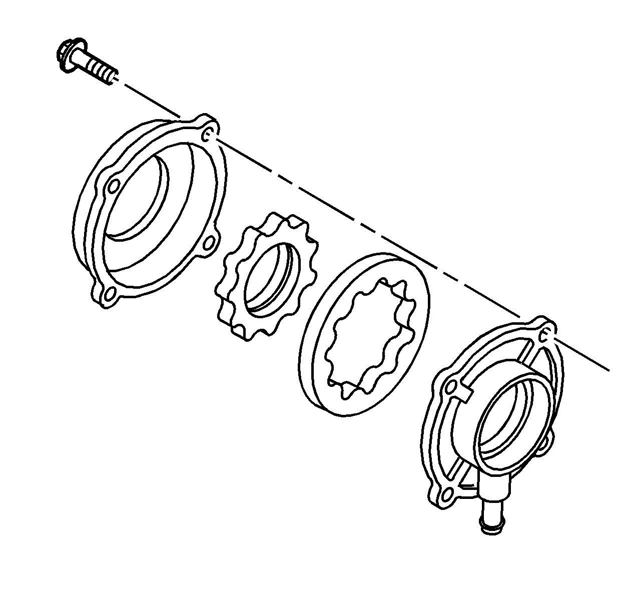
- Remove the oil pump suction hose from the
oil pump screen.
- Clean the hose and screen in cleaning solvent and air dry.
- If the screen is embedded with debris, replace the screen.
- Inspect the hose for cracking or tears.
- Replace the hose if it is faulty.
- Inspect the oil pump for free movement.
- Inspect for wear on the oil pump drive teeth.
- If there is binding or worn teeth, replace the oil pump. Do not disassemble
the oil pump. The oil pump is serviced as a unit.
High/Low Range Components
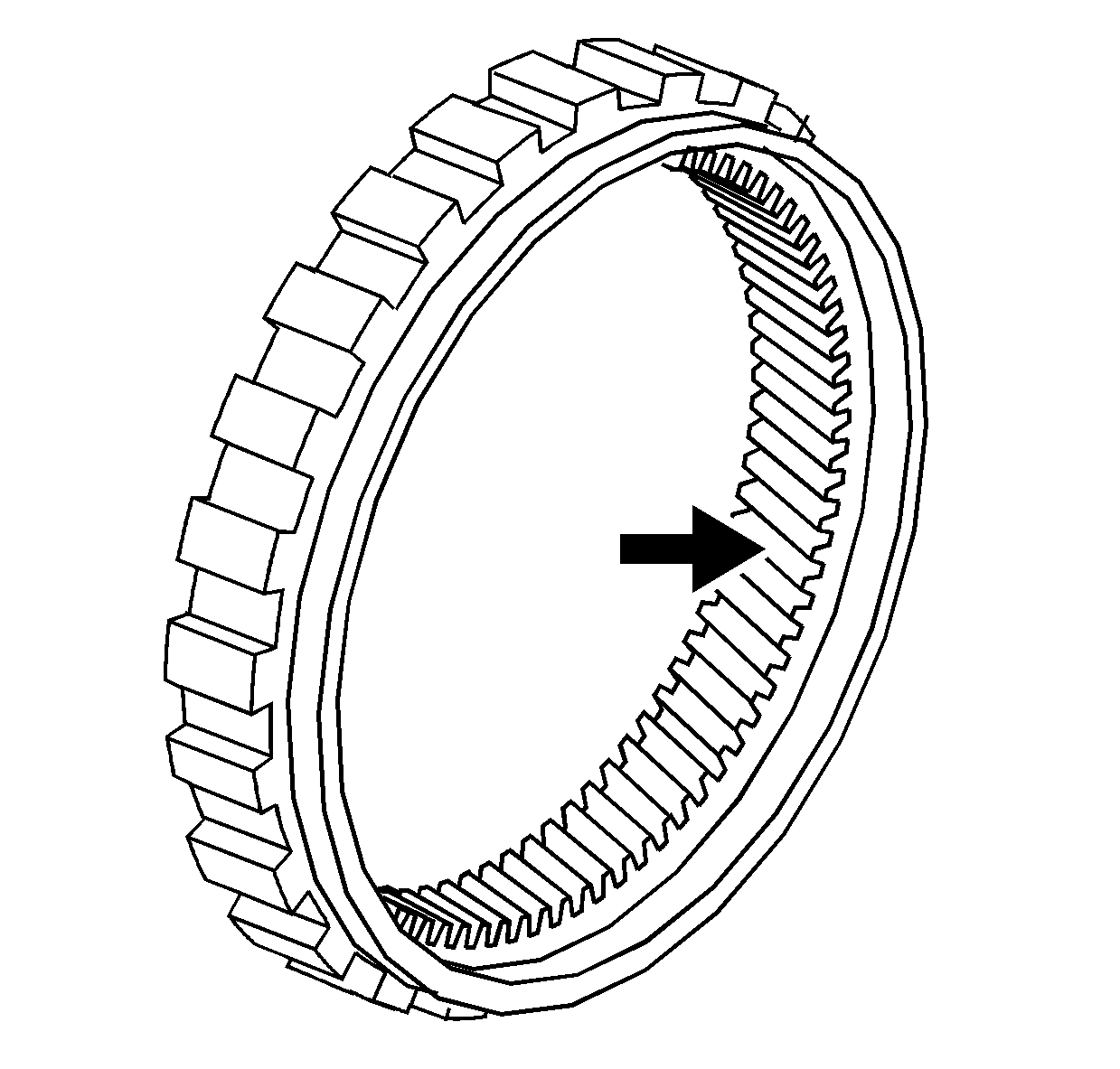
- Clean the annulus gear in cleaning solvent
and air dry.
- Inspect the annulus gear teeth for the following conditions:
| • | Damage or excessive wear |
| • | Debris embedded in the root of the teeth |
- Replace the annulus gear if it is faulty.
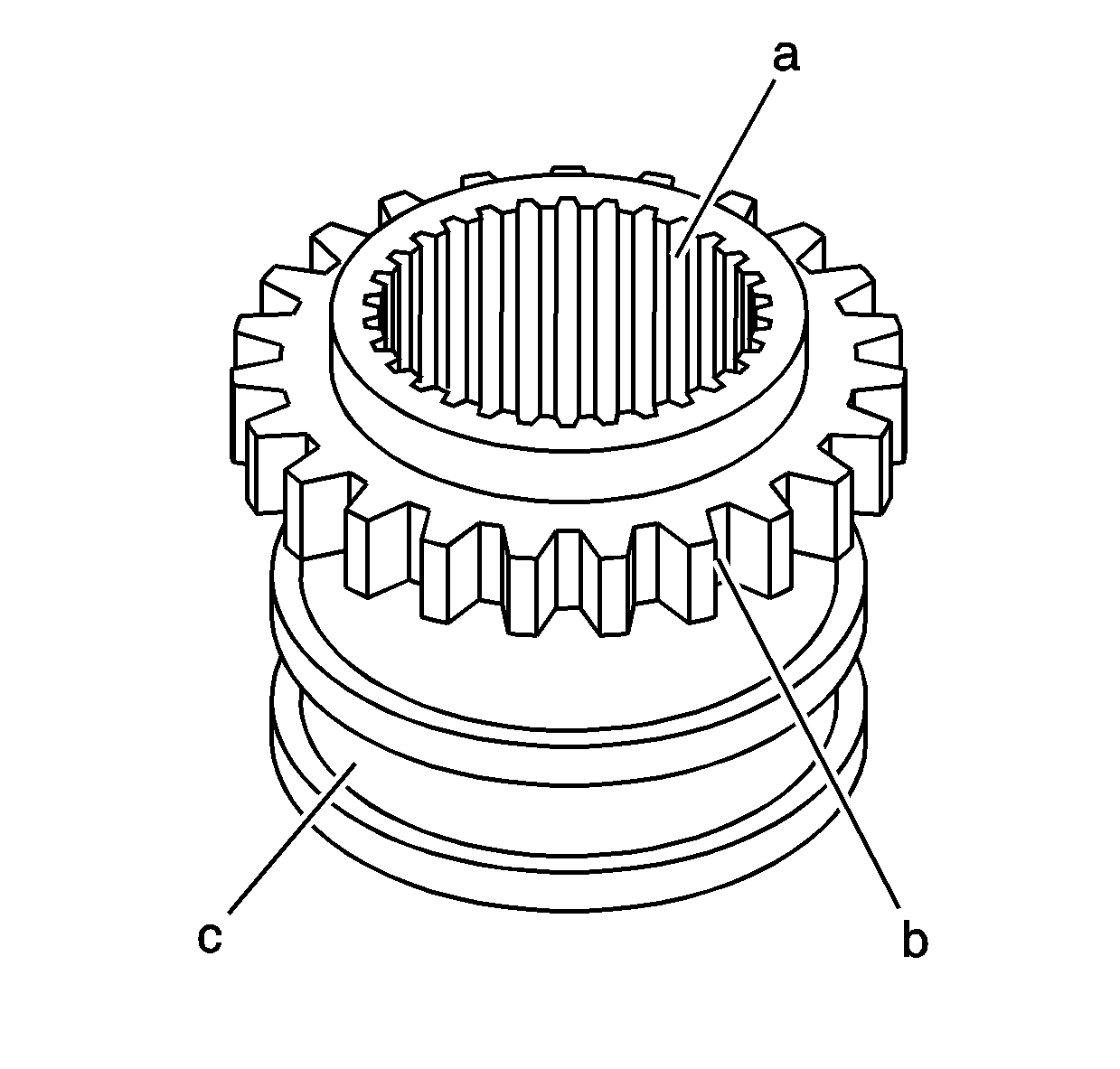
- Clean the high/low range shift sleeve in
cleaning solvent and air dry.
- Inspect the high/low range shift sleeve for the following conditions:
| • | Excessive wear or roughness on the shift fork pad surface (c) |
| • | Damaged, chipped or excessively worn engagement teeth (b) |
| • | Excessively loose or gouged rear output shaft splines (a) |
- Replace the high/low range shift sleeve if any of the above conditions
are found.
High/Low Planetary Carrier Assembly
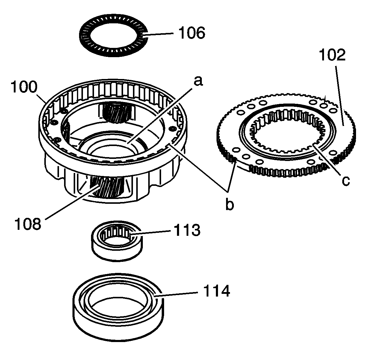
- Clean the high/low planetary carrier (100)
and the planetary low gear (102) in cleaning solvent. Do not disassemble
the planetary carrier.
- Air dry and ensure all cleaning solvent is removed from the bearings
in the pinion gears (108). Do not spin the pinion gears with compressed air.
- Inspect the pinion gears for chipped teeth.
- Inspect the pinion gears for debris embedded in the root of the teeth.
- Inspect the pinion gears for excessive side movement from worn bearings
or shafts.
- Inspect the low range teeth (c) on the planetary low gear (102)
for damage or excessive wear.
- Inspect the planetary low gear and planetary carrier teeth (b)
for excessive wear.
- Inspect the thrust washer surface (a) for scoring or excessive
wear.
- Replace the high/low planetary carrier if any of the above conditions
are found. The planetary low gear is serviced only with the planetary carrier assembly.
- Inspect the planetary carrier bearing (114), the input shaft bearing (113)
and the thrust bearing (106) for the following conditions:
- Replace faulty bearings. Refer to
Transfer Case Disassemble
and
Transfer Case Assemble
.
Drive Chain and Sprockets
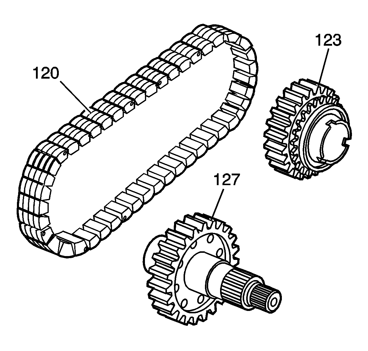
- Clean the drive chain (120), the
drive sprocket (123) and the front output shaft (127) in cleaning solvent
and air dry.
- Inspect the drive chain (120) for the following conditions:
| • | Debris embedded in the links |
| • | Stretched chain - interference marks on the case half |
- Replace the chain if any of the above conditions are found.
- Inspect the driven sprocket on the front output shaft (127) and
the drive sprocket (123) for the following conditions:
| • | Chipped or cracked teeth |
| • | Excessively worn gear surfaces |
| • | Slight wear marks are normal. |
| • | Debris embedded in the root of the teeth |
- Inspect the drive sprocket (123) for the following conditions:
| • | 2/4 Synchronizer engagement teeth for chipping |
| • | 2/4 Synchronizer engagement teeth for excessive wear |
- Inspect the drive sprocket bushing for the following conditions:
- Inspect the rear bearing journal on the front output shaft for the following
conditions:
- Inspect the threads on the front output shaft for damage.
- Inspect the splines on the front output shaft for wear, caused by a loose
flange yoke.
- Replace the sprockets if any of the above conditions are found. The chain
and sprockets may be replaced separately.
Rear Output Shaft
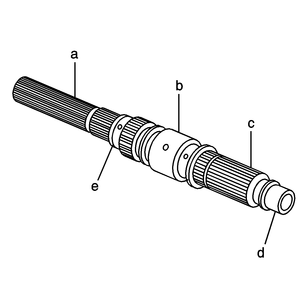
- Clean the rear output shaft in cleaning
solvent.
- Clean the rear output shaft oil galleries and air dry.
Important: Do not attempt to smooth any roughness in
the bearing journals.
- Inspect the bearing journals on the rear output shaft for the following conditions:
| • | The front support bearing (d) |
| • | The drive gear bushing (b) |
- Inspect the rear output shaft high/low range splines (c) for damage
or excessive wear. Witness marks at the location of the gear are normal.
- Inspect the rear output shaft splines (a) for wear or damage.
- Inspect the rear output shaft bearing area (e) for a spun bearing.
- Replace the rear output shaft if any of the above conditions are found.
Shift System Components
Tools Required
J 22738-B Valve Spring
Tester
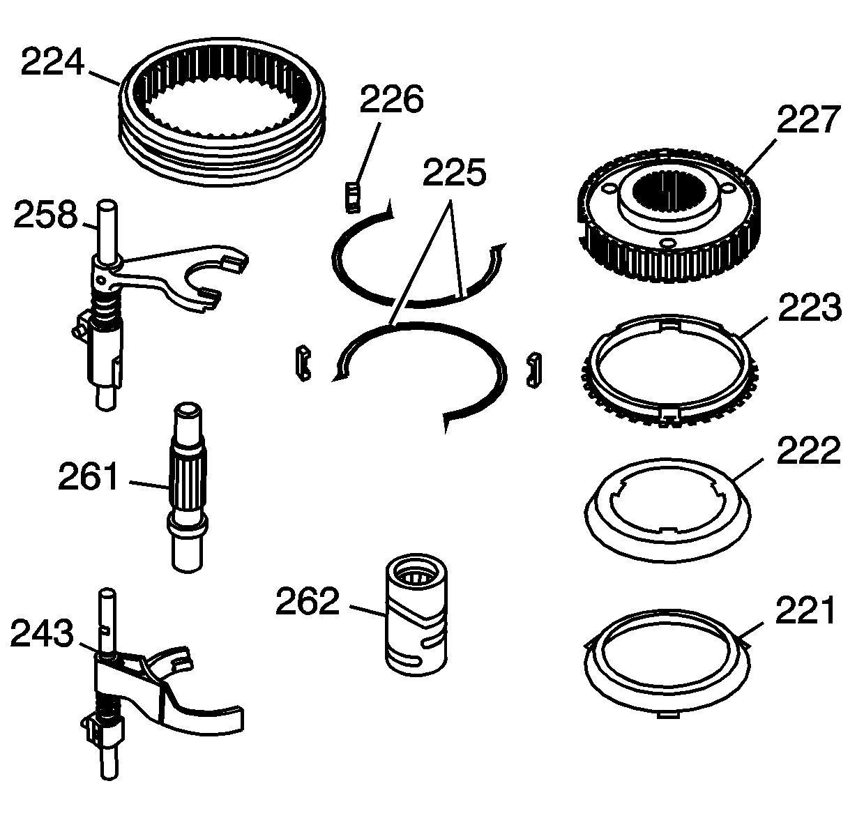
- Clean the following shift system components
in cleaning solvent and air dry:
| • | The 2/4 synchronizer sleeve (224) |
| • | The 2/4 shift fork (243) |
| • | The control actuator shaft (261) |
| • | The high/low shift fork (258) |
| • | The control actuator cam (262) |
| • | The 2/4 synchronizer inserts (226) and springs (225) |
| • | The 2/4 synchronizer hub (227) |
| • | The 2/4 synchronizer rings (223, 222 and 221) |
- Inspect the control actuator cam (262) surfaces for the following
conditions:
- Replace the control actuator cam if faulty.
- Inspect the control actuator shaft (261) for the following conditions:
| • | Wear at the seal surface |
| • | Actuator assembly engagement teeth stripped or excessively worn |
- Replace the control actuator shaft if faulty.
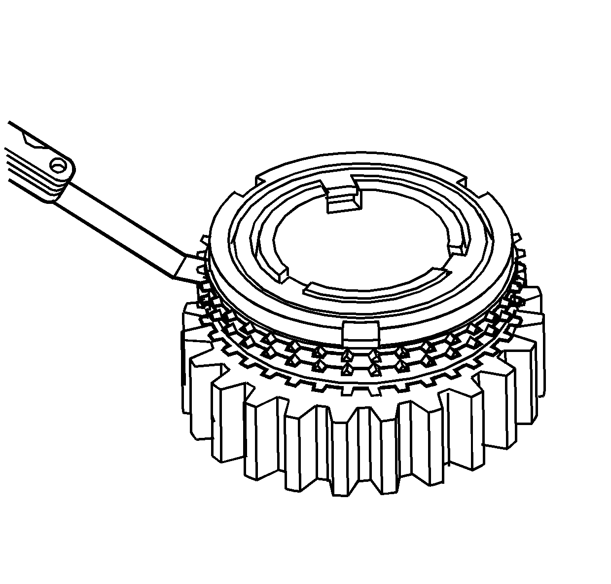
- Inspect the 2/4 synchronizer blocking ring (223)
for chipped or worn engagement teeth.
- Install the 2/4 synchronizer rings on the drive gear.
- Using a feeler gage between the blocking ring teeth and the drive gear
selector teeth, measure the synchronizer wear. Press down evenly on the rings while
measuring.
Specification
| • | Standard clearance: 1.5 mm (0.059 in) |
| • | Minimum clearance: 0.8 mm (0.031 in) |
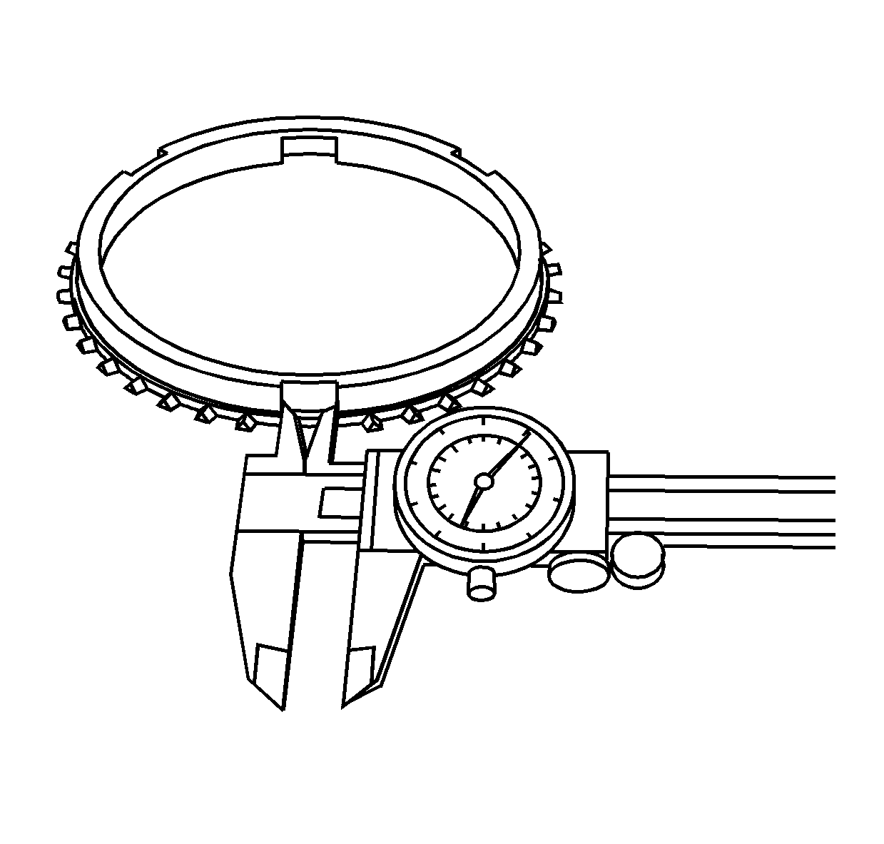
- Measure the slots for the inserts, in the
blocking ring (223), for wear.
Specification
Standard dimension: 9.5-9.7 mm
(0.374-0.382 in)
- Replace the 2/4 synchronizer rings if they are faulty.
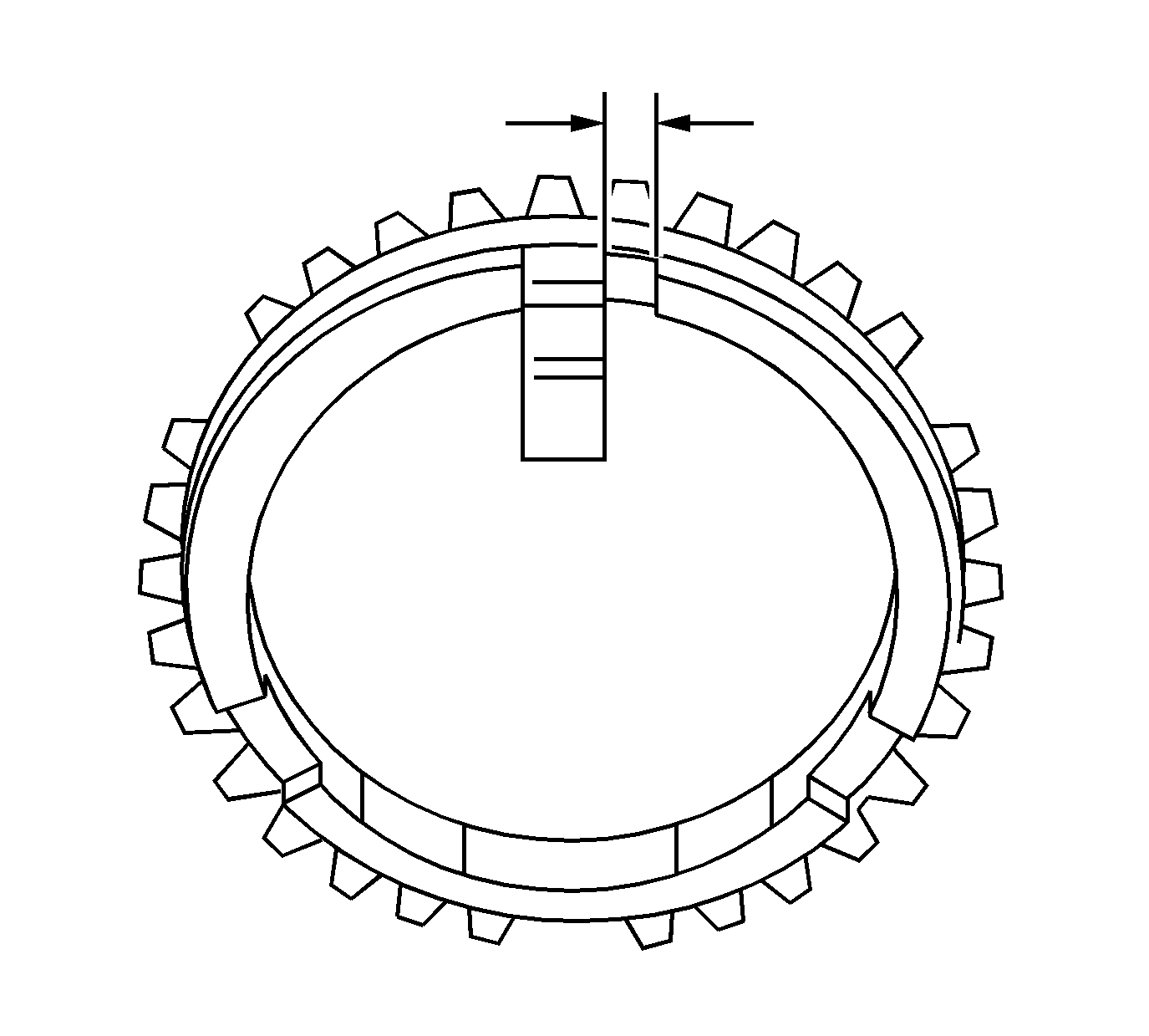
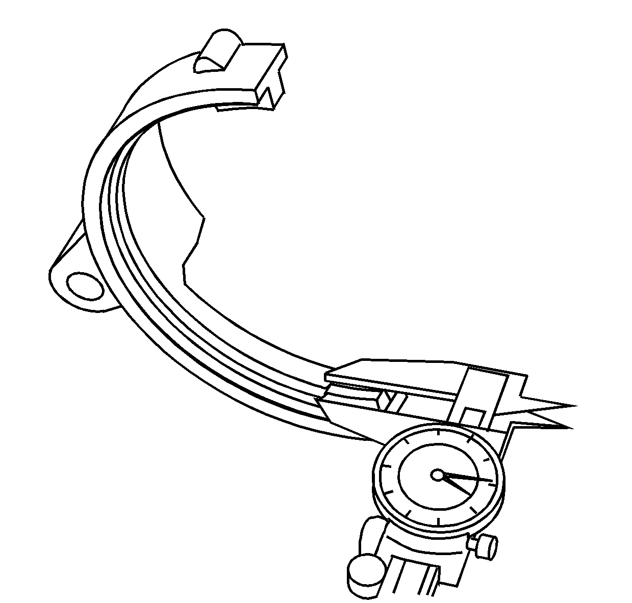
- Using a vernier caliper, measure the clearance
between the blocking ring and the insert.
- If the measured value exceeds the specified limit, the blocking ring and
the insert must be replaced.
Specification
| • | Standard blocking ring and insert clearance: 3.86-4.14 mm
(0.152-0.163 in) |
| • | Limit blocking ring and insert clearance: 4.9 mm (0.193 in) |
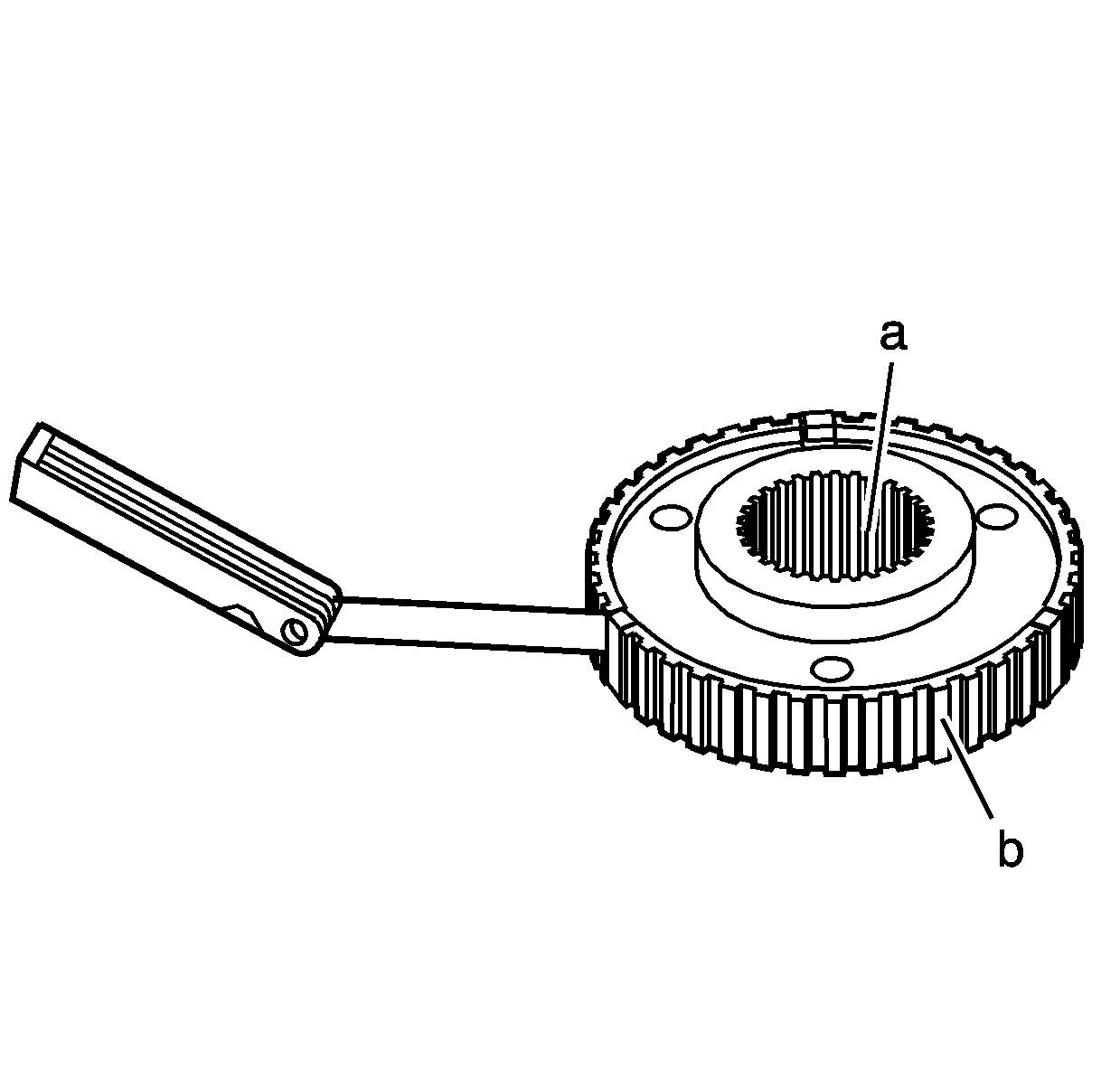
- Inspect the 2/4 synchronizer hub for the
following conditions:
| • | Splines (a) press fit to the rear output shaft |
| • | Steps worn in the sleeve teeth (b) |
- Install the inserts in the hub slots.
- Using a feeler gage, measure for wear.
Specification
| • | Standard clearance: 0.01-0.19 mm (0.0004-0.0075 in) |
| • | Maximum clearance: 0.3 mm (0.012 in) |
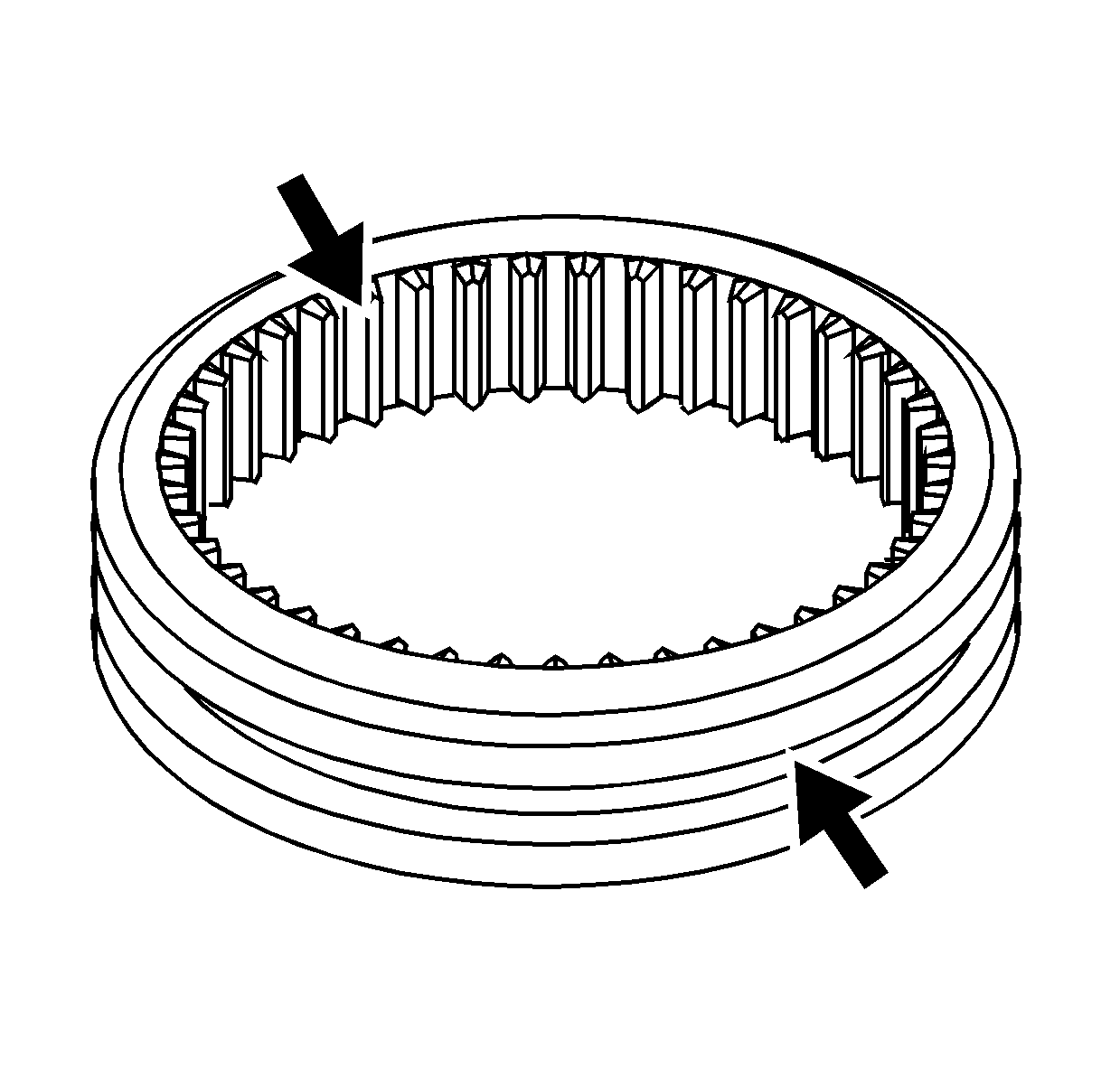
- Inspect the 2/4 synchronizer sleeve for
the following conditions:
| • | Chipped or worn blocking ring teeth |
| • | Loose fit to the synchronizer hub caused by excessive wear |
| • | Shift fork collar surfaces for damage |
- Inspect the 2/4 synchronizer inserts for excessive wear.
- Replace the 2/4 synchronizer assembly if any of the above conditions
are found.
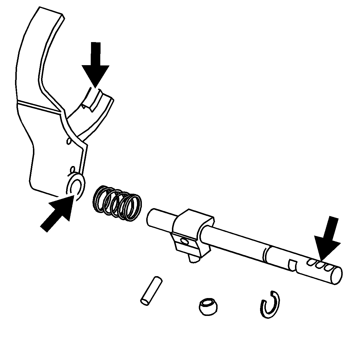
- Inspect the 2/4 shift shaft for excessive
wear at the detent notches.
- Inspect the 2/4 shift fork for excessive wear at the synchronizer sleeve
surfaces.
- Inspect the 2/4 shift fork for cracks or being bent.
- Inspect the 2/4 shift fork shaft bore for excessive wear.
- Replace any faulty or damaged components. Refer to
Transfer Case Disassemble
and
Transfer Case Assemble
.
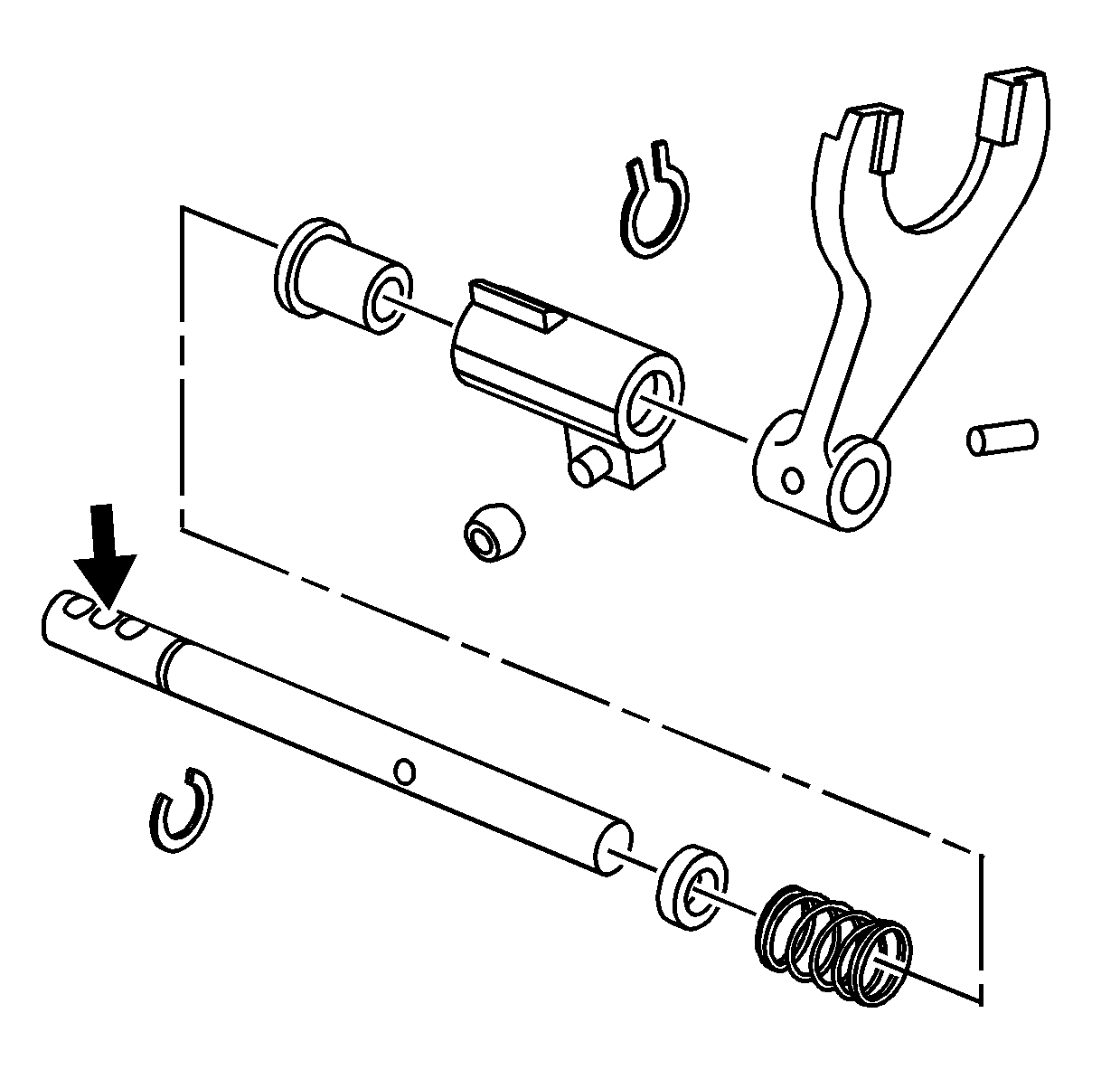
- Inspect the high/low shift shaft for excessive
wear at the detent notches.
- Inspect the high/low shift block and collars for wear.
- Replace any of the above components if they are found faulty. Refer to
Transfer Case Disassemble
and
Transfer Case Assemble
.
- Measure the sleeve pads on both shift forks
for wear.
Specification
| • | 2/4 wheel drive shift fork standard thickness: 9.60-9.85 mm
(0.378-0.388 in) |
| • | 2/4 wheel drive shift fork minimum thickness: 9.0 mm (0.354 in) |
| • | High/Low shift fork standard thickness: 7.60-7.85 mm (0.299-0.309 in) |
| • | High/Low shift fork minimum thickness: 7.0 mm (0.276 in) |
- If the measured value is less than the minimum thickness, replace the
shift fork. Refer to
Transfer Case Disassemble
and
Transfer Case Assemble
.
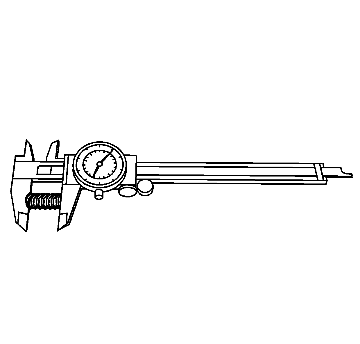
- Inspect the detent springs for distortion
or cracks.
- Measure the detent spring free length.
Specification
| • | Standard length: 23.4 mm (0.92 in) |
| • | Minimum length: 23.1 mm (0.91 in) |
- Measure the inner range shift detent spring free length.
Specification
| • | Standard length: 26.6 mm (1.05 in) |
| • | Minimum length: 25.6 mm (1.01 in) |
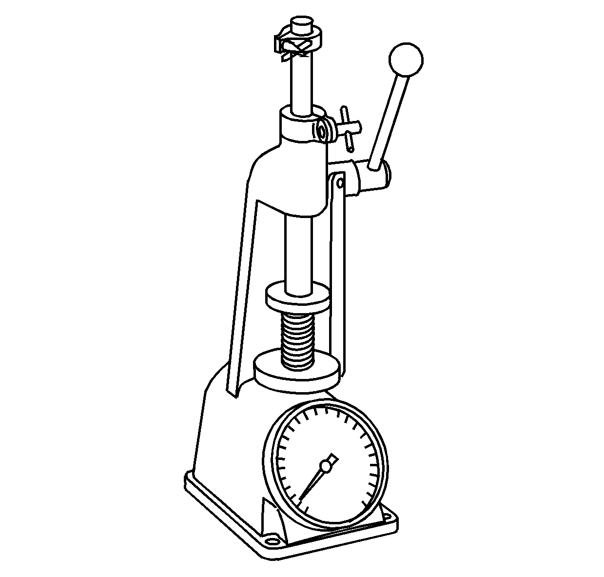
- Use J 22738-B
or equivalent to measure the detent spring tension.
Specification
| • | Compressed height: 18.7 mm (0.736 in) |
| • | Standard tension: 7.5-8.5 kg (16.5-18.7 lb) |
- Use J 22738-B
or equivalent
to measure the inner range shift detent spring tension.
Specification
| • | Compressed height: 18.7 mm (0.736 in) |
| • | Standard tension: 3.3-4.3 kg (7.3-9.5 lb) |
- Replace the detent springs if found faulty.


