SER. MAN. UPDATE SEC. 8A ELECT. GAUGE DIAG. REVISED

Subject: GAGE AND INDICATOR DIAGNOSTIC TEXT
Model and Year: 1988-90 CORSICA/BERETTA
TO: ALL CHEVROLET DEALERS
The 1988, 1989 and 1990 Chevrolet Corsica/Beretta Service Manuals contain inaccurate coolant temperature gage and indicator information in Section 8A. Please write in the Troubleshooting Hints section in Section 8A-81 of the above Service Manuals to ignore the coolant temperature gage and indicator diagnostic text and follow the service bulletin for gage and indicator problem diagnosis. Please insert pages 0 thru 3 of the service bulletin into Section 8A-81 of your copies of the 1988, 1989 and 1990 Chevrolet Corsica/Beretta Service Manuals. Also make the following changes to your copies of the 1988 and 1989 Chevrolet Corsica/Beretta Service Manuals.
Year Old Page Remove New Page Add ---- ----------------- ------------- 1988 8A-80-1 8A-80-1 1989 8A-80-1 8A-80-1 1989 8A-81-3 8A-81-3
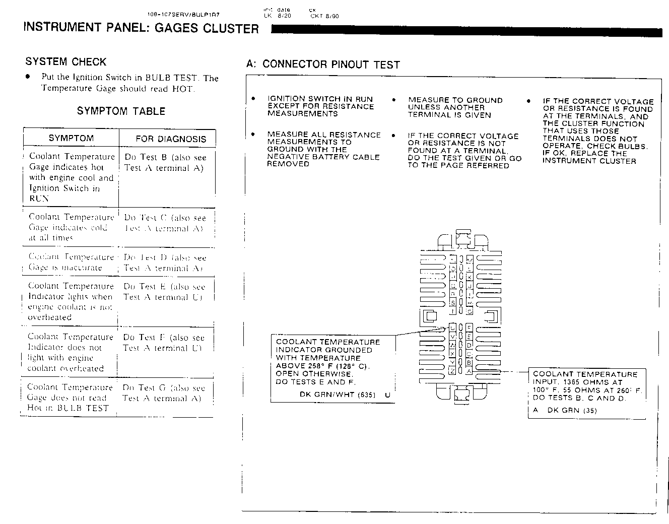
INSTRUMENT PANEL: GAGES CLUSTER ------------------------------- SYSTEM CHECK
- Put the Ignition Switch in BULB TEST. The Temperature Gage should read HOT.
SYMPTOM TABLE
SYMPTOM FOR DIAGNOSIS ------------------------ ------------------------------- Coolant Temperature Gage Do Test B (also see Test A terminal indicates hot with engine A) cool and Ignition Switch in RUN.
Coolant Temperature Gage Do Test C (also see Test A terminal indicated cold at all times A)
Coolant Temperature Gage Do Test D (also see test A terminal inaccurate A)
Coolant Temperature Indicator Do Test E (also see Test A terminal lights when engine coolant is U) not overheated
Coolant Temperature Indicator Do Test F (also see test A terminal does not light with engine U) coolant overheated
Coolant Temperature Gage Do Test G (also see Test A terminal does not read Hot in A) BULB TEST
INSTRUMENT PANEL: GAGES CLUSTER -------------------------------
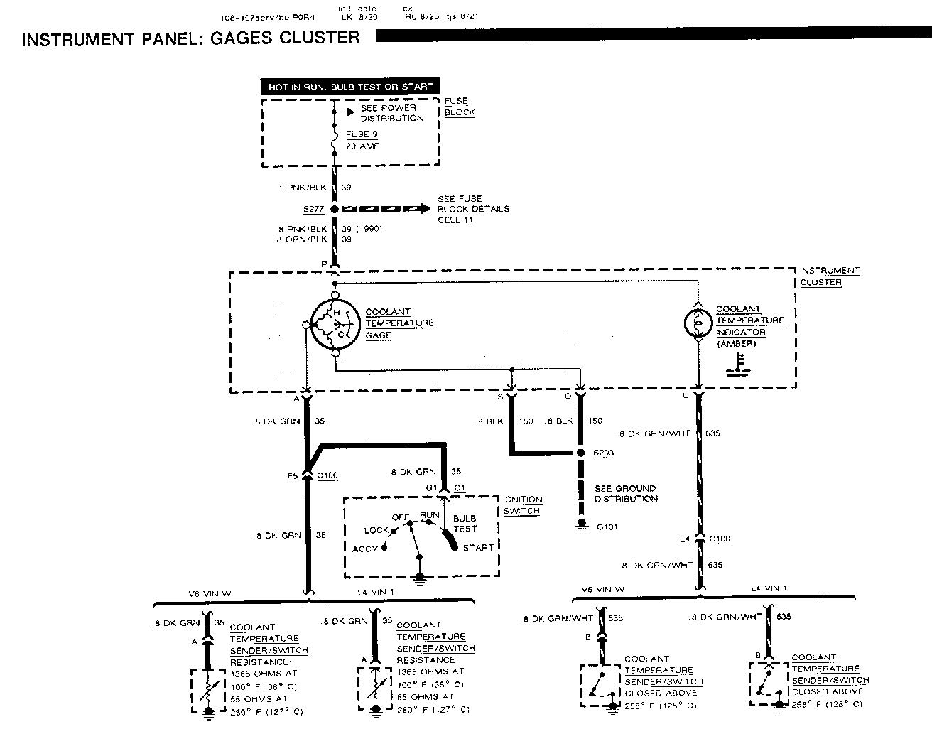
B: COOLANT TEMPERATURE GAGE SHORT TEST -------------------------------------- Disconnect the Coolant Temperature Sender/Switch connector and turn the Ignition Switch to RUN.
- If the Coolant Temperature Gage reads Cold, replace the Coolant Temperature Sen- der/Switch.
- If the Coolant Temperature Gage does not read Cold, check the DK GRN (35) wire for a short to ground (see schematic). Replace the Instrument Cluster if wire is good (see Section 8C).
C: COOLANT TEMPERATURE GAGE OPEN TEST ------------------------------------- Disconnect the Coolant Temperature Sender/ Switch connector. Jumper the DK GRN (35) wire to ground and turn the Ignition Switch to RUN.
- If the Coolant Temperature Gage reads Hot, replace the Coolant Temperature Sender/ Switch.
- If the Coolant Temperature Gage still reads cold, check the DK GRN (35) wire, and Gage connections for an open. If OK, replace the Instrument Cluster (see Section 8C).
D: COOLANT TEMPERATURE GAGE ACCURACY TEST
Disconnect the Coolant Temperature Sender/ Switch connector. Connect one red clip lead of the J-33431 tester to the harness connector DK GRN (35) wire, and the other red clip lead to ground. Adjust the resistance dials of the tester to 1400 ohms and then to 55 ohms. The Coolant Temperature Gage should show Cold and then Hot.
- If the Coolant Temperature Gage reads correctly, the wiring and Gage are good. Replace the Coolant Temperature Sender/Switch.
- If the Gage is not correct, check the Gage connection and the DK GRN (35) wire for high resistance. If OK, replace the Instrument Cluster (see Section 8C).
E. COOLANT TEMPERATURE INDICATOR SHORT TEST -------------------------------------------- Disconnect the Coolant Temperature Switch Connector and turn the Ignition Switch to RUN.
- If the Indicator stays on, check the DK GRN/ WHT (35) wire for a short to ground.
- If the Indicator goes out, replace the Coolant Temperature Switch.
F. COOLANT TEMPERATURE INDICATOR OPEN TEST ------------------------------------------- Connect: FUSED JUMPER
AT:COOLANT TEMPERATURE SWITCH CONNECTOR (Disconnected)
Condition: Ignition Switch: RUN
Jumper Correct For Between Result Diagnosis ----------------- ------------------- ---------- B (DK GRN/WHT) & Coolant Temperature See 1 Ground Indicator comes on
- If the result is correct, replace Coolant Temperature Sender/Switch.
1 Check DK GRN (35) wire and Instrument Cluster Printed Cluster for an open.
G: IGNITION SWITCH TEST ----------------------- Measure: RESISTANCE
AT:IGNITION SWITCH (Disconnected)
Condition: Ignition Switch: BULB TEST and START
Measure Correct For Between Resistance Diagnosis -------------- ---------- ---------- C1/G1 & Ground 0 ohms See 1
- If the resistance is correct, check/repair DK GRN (35) wire for an open (see schematic). If OK, replace the Instrument Cluster (see Section 8C).
1 Replace the Ignition Switch.
CIRCUIT OPERATION
Coolant Temperature Indicator
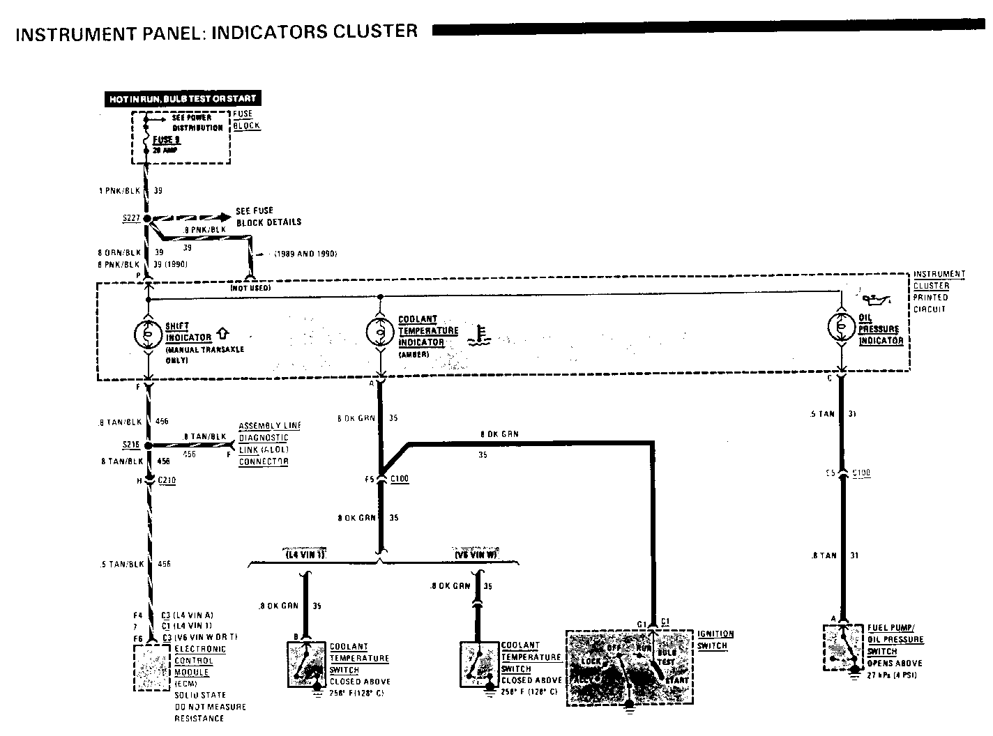
The Coolant Temperature Indicator warns the driver of high coolant temperature. With the Ignition Switch in RUN, BULB TEST or START, voltage from Fuse 9 is applied to the Coolant Temperature Indicator. In RUN, the bulb can be grounded through the Coolant Temperature Switch. The Switch closes when the coolant temperature exceeds 258 Deg. F (126 Deg C). The fight glows.
INSTRUMENT PANEL: GAGES CLUSTER ------------------------------- Coolant Temperature Gage
The Coolant Temperature Gage is operated by two coils. Battery voltage is applied to both coils in series. The Junction between the two coils is grounded through the Coolant Temperature Sender. This has 55 ohms resistance at 260 Deg. F (hot coolant) and its resistance increases at lower temperatures. Resistance is approximately 1400 ohms at 100 Deg. F. This causes the currents in the coils to vary and this moves the pointer. In BULB TEST or START, the coolant temperature input is grounded through the Ignition Switch forcing the gage to read Hot as a gage check.


General Motors bulletins are intended for use by professional technicians, not a "do-it-yourselfer". They are written to inform those technicians of conditions that may occur on some vehicles, or to provide information that could assist in the proper service of a vehicle. Properly trained technicians have the equipment, tools, safety instructions and know-how to do a job properly and safely. If a condition is described, do not assume that the bulletin applies to your vehicle, or that your vehicle will have that condition. See a General Motors dealer servicing your brand of General Motors vehicle for information on whether your vehicle may benefit from the information.
