EXCESSIVE CLUTCH PEDAL TRAVEL HYDRAULIC CLUTCH SERVICE INFO.

Subject: DECREASED PERFORMANCE IN CLUTCH SYSTEM
Model and Year: 1989-91 CAMARO, CAVALIER, CORSICA AND BERETTA WITH MANUAL TRANSMISSION 1990-91 LUMINA WITH MANUAL TRANSMISSION
CONDITION:
---------- Some owners of 1989-91 F, J, L, and W vehicles may experience decreased performance in their clutch system such as more than normal clutch pedal travel, clutch slippage, etc.
CAUSE:
------ The above condition may be due to the improper procedures used in re-installing the hydraulic clutch system after service.
CORRECTION:
------------ This bulletin is to advise the proper procedure to remove or install the hydraulic clutch system and also the parts available to assist in such installations. (SEE ATTACHED TABLE 1 for parts usage and parts identification.)
Parts are currently available from GMSPO.
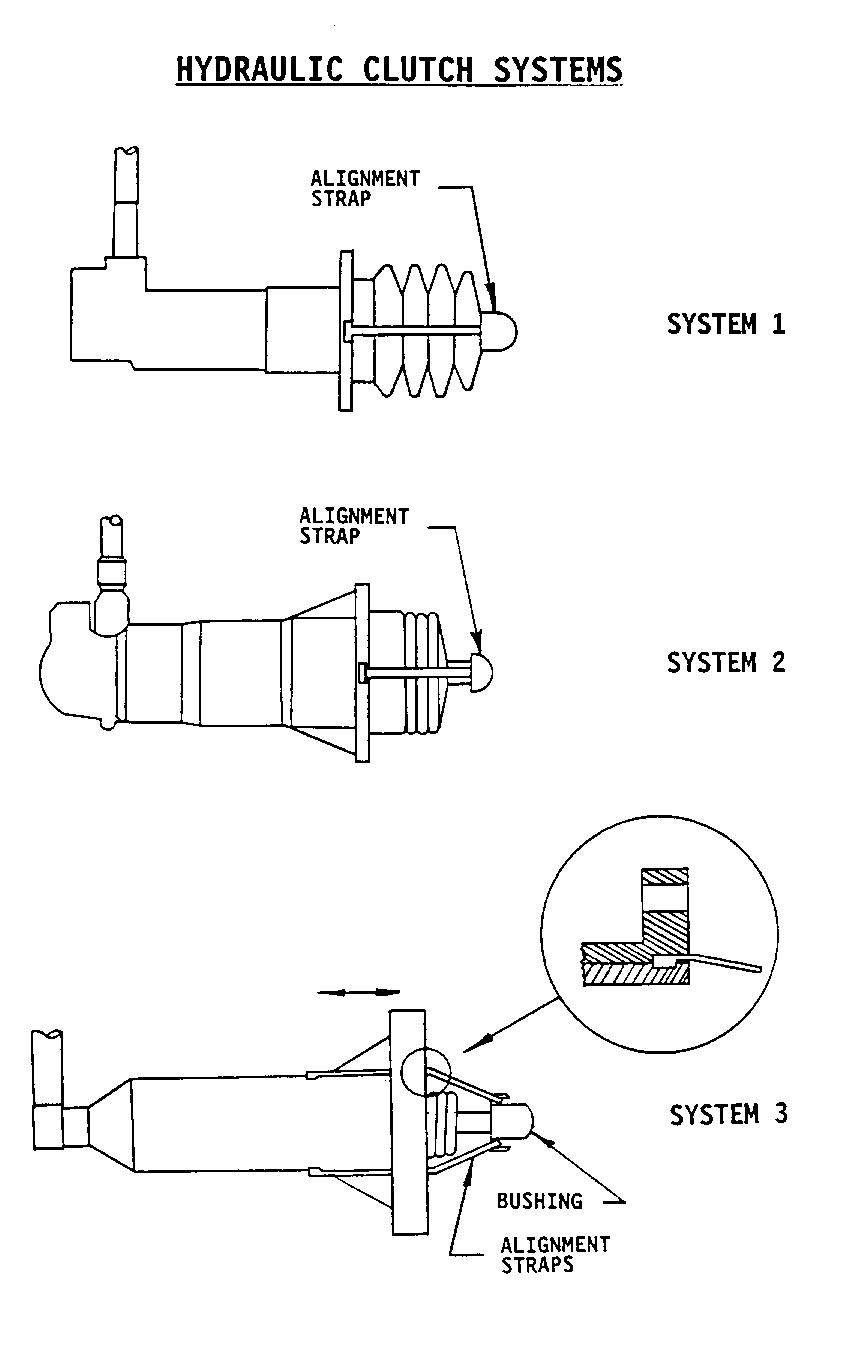
See figures to identify the various hydraulic clutch systems. The master cylinder is attached to the front of the dash. The slave/actuator cylinder is attached to the clutch housing. Care must be taken in order not to overextend the hydraulic slave/actuator cylinder. Such overextension will damage the slave/actuator cylinder, leading to a possible leak or complete failure of the system.
Before removing the hydraulic slave/actuator cylinder, verify that the clutch pedal is in the fully returned position. Also, anytime that the slave/actuator cylinder is removed from its mounted position or disengaged from the clutch fork, DO NOT depress the clutch pedal while it is engaged to the master cylinder push rod. Nor should the master cylinder push rod be manually depressed in order to extend the slave/actuator cylinder.
If the removed hydraulic clutch system is to be reused, the slave/actuator cylinder alignment strap must immediately be installed onto the slave/actuator cylinder to prevent any accidental extension of the slave/actuator cylinder push rod. See TABLE 1 for applicable alignment strap part numbers. This strap is required for the alignment of the push rod to the clutch fork during reinstallation.
IMPORTANT: The strap must be used whenever clutch system work is performed. Do NOT cut the alignment strap. It will automatically fracture during the first clutch pedal stroke.
Procedures to remove and install alignment strap:
1. Remove existing alignment strap and bushing from slave/actuator cylinder. SYSTEM 3 will require the releasing of the lock tabs and sliding the mounting flange down the slave/actuator cylinder housing in order to access the ends of the alignment strap (See Figure).
2. Install the new alignment strap and bushing, if applicable, onto the end of the slave/actuator cylinder push rod.
3. Depress the push rod fully into the slave/actuator cylinder.
4. Snap both ends of alignment strap onto the sides of the slave/actuator cylinder housing (See Figure).
For SYSTEM 3, slide the mounting flange back to its original position. Make sure the tabs are locked in place (See Figure).
When installing the hydraulic clutch system, verify that the slave/actuator cylinder is in the retracted position WITH the alignment strap in place. The alignment strap must already be in place with a new hydraulic system. If not, return the assembly for another assembly. If the system is new, the plastic push rod stop on the master cylinder push rod must also be removed before pushing the clutch pedal. Also, visually inspect the slave/actuator cylinder for signs of overextension, such as cracks or leakage.
IMPORTANT: Also, inspect for sufficient clearance for the clutch pedal and master cylinder push rod in the fully returned position. This will insure there is an adequate amount of hydraulic fluid going to the slave/actuator cylinder.
Anytime during the installation of the hydraulic clutch system, do NOT extend the slave/actuator cylinder or depress the clutch pedal until the slave/actuator cylinder is installed in its proper location AND is aligned to the clutch fork.
After correctly installing the slave/actuator cylinder, depress the clutch pedal to fracture the alignment strap. The hydraulic system is now functional and will self-adjust to the.vehicle.
Refer to Section 7C of the Service Manual for remaining service procedures for the hydraulic clutch system.
Use applicable Labor Codes and Time.
TABLE 1 | | HYDRAULIC | USAGE | ALIGNMENT STRAP(S) SYSTEM | (MODEL YEAR & BODY) | PART NO. ------------|--------------------------------|------------------- | | 1 | ALL "F" | 10186887 ------------|--------------------------------|------------------- | 1989: ALL "J", ALL "L"; | | "N" w/ 2.5L ENGINE | 2 | | 10186888 | 1990- ALL "J", "L", & "N" | | 1991: w/ Isuzu TRANSAXLE | ------------|--------------------------------|------------------- | 1989- "N" w/ QUAD-4 ENGINE | | 1991: ALL "W" | 10186889 3 | | | 1990- "J" & "L" w/ HM282 | 10104490 | 1991: TRANSAXLE | (BUSHING) | |

General Motors bulletins are intended for use by professional technicians, not a "do-it-yourselfer". They are written to inform those technicians of conditions that may occur on some vehicles, or to provide information that could assist in the proper service of a vehicle. Properly trained technicians have the equipment, tools, safety instructions and know-how to do a job properly and safely. If a condition is described, do not assume that the bulletin applies to your vehicle, or that your vehicle will have that condition. See a General Motors dealer servicing your brand of General Motors vehicle for information on whether your vehicle may benefit from the information.
