SERVICE MANUAL UPDATE-SEC.6E3 DRIVEABILITY AND EMISSIONS

Subject: REVISED DRIVEABILITY AND EMISSIONS A-3 DIAGNOSTIC CHART
Model and Year: 1992 CAVALIER, BERETTA AND CORSICA WITH 2.2 LENGINE
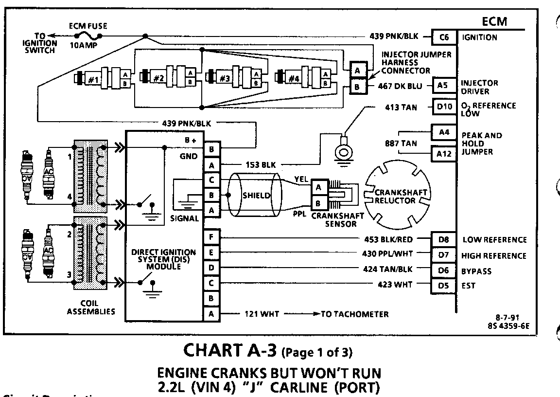
This bulletin serves to revise Section 6E3 "Driveability and Emissions" in the 1992 "J" and "L" Carline 2.2L (VIN 4 - RPO LN2) Service Manual.
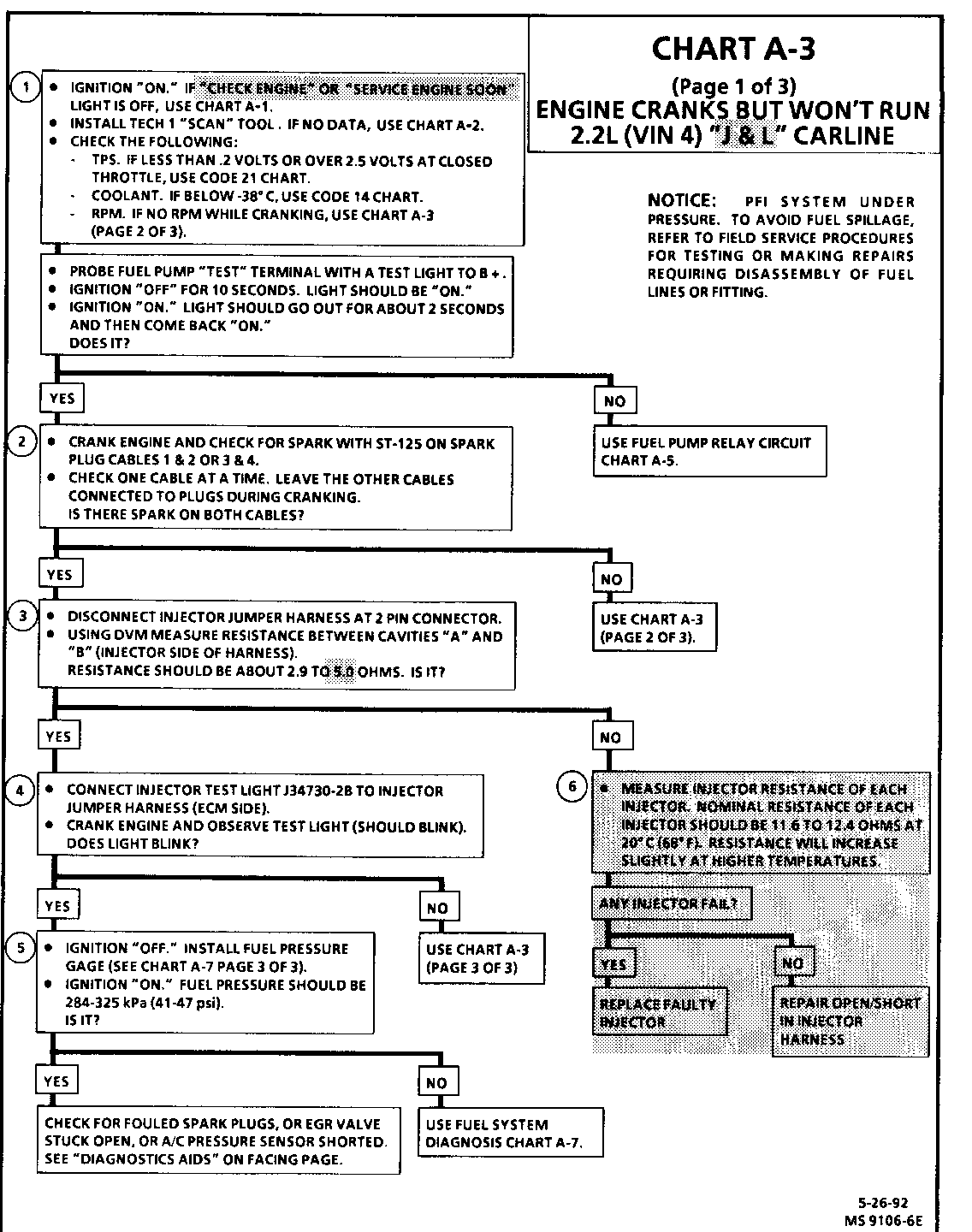
To "Engine Cranks But Won't Run:" revise injector parallel test on Chart A-3 (Page 1 of 3) on Page 6E3-A-19 "J" and "L' Carline. Changed upper threshold of injector in parallel test from 3.1 to 5.0 ohms. Also added additional logic to check resistance of each injector at 20 degrees Celsius (68 degrees Fahrenheit) if injector parallel test fails. The injector parallel test is designed to check for problems that would cause a no start condition only. Additional checks have been added to "SYMPTOMS" section to test complete injector circuit.
To "SYMPTOMS" section, revise Fuel System Check in "LACK OF POWER, SLUGGISH OR SPONGY" Chart on Page 6E3-B-7 "J" and 6E3-B-8 "L". Added additional test to check injector resistance. Each injector should be 11.6 to 12.4 ohms at 20 degrees Ceisius (68 degrees Fahrenheit).
To "SYMPTOMS" section, revise Fuel System Check in "HESITATION, SAG, STUMBLE" Chart on Page 6E3- B-9 "J" and 6E3-B-11 "L". Added additional test to check injector resistance. Each injector should be 11.6 to 12.4 ohms at 20 degrees Celsius (68 degrees Fahrenheit).
To "SYMPTOMS" section, revise Fuel System Check in "CUTS OUT, MISSES" Chart (Page 2 of 2) on Page 6E3-B-11 "J" and 6E3-B-13 "L". Added additional test to check injector resistance. Each injector should be 11.6 to 12.4 ohms at 20 Celsius (68 degrees Fahrenheit).
Circuit Description:
Before using this chart, battery condition, engine cranking speed, and fuel quantity should be checked and verified as being OK.
Test Description: Number(s) below refer to circled number(s) on the diagnostic chart.
1. o A "Check Engine" light "ON" is a basic test to determine if there is battery and ignition voltage at the ECM.
o No ALDL data may be the result of an ECM problem, and CHART A-2 will diagnose an ECM problem.
o If TPS is less than .2 volts, the TPS 5 volt reference circuit could be shorted to ground. it TPS is over 2.5 volts, the ECM could be in the "Clear Flood Mode" which may cause the engine to not start.
2. Because the Direct Ignition System (DIS) uses two plugs and wires to complete the circuit of each coil, the opposite spark plug wire should be left connected. If rpm was indicated during crank, the ignition module is receiving a crank signal, but "No Spark" at this test indicates the ignition module is not triggering the coil.
3. This test is performed with injectors 1,2,3 & 4 in parrallel.
4. This test light should flash, indicating that the ECM is controlling the injectors. How bright the light flashes is not important.
5. Ignition may have to be cycled "ON" several times to obtain maximum fuel pressure.
6. Damage to ECM injector driver may occur if any injector resistance measures less than 11.6 ohms (internal short to ignition CKT 439).
Diagnostic Aids
o Water or contamination in fuel system may cause a no start condition during very cold or freezing weather. The engine may start after approximately 5 minutes in a heated shop. The problem may not recur until an overnight park in very cold or freezing temperatures
o An EGR valve stucking open can cause a rich air/fuel ratio during cranking. Unless the ECM enters "Clear Flood Mode" at the first indication of a flooding condition, it may result in a no start condition.
o Low fuel pressure can result in a very lean air/fuel ratio, see CHART A-7.
o An A/C pressure sensor with an internal short to ground can cause a no start condition. Disconnect the A/C pressure sensor. In vehicle starts, replace faulty sensor.
o A MAP sensor stuck between .5 and 2.5 volts can cause a no start condition. Disconnect the MAP sensor. If vehicle starts, replace faulty sensor.
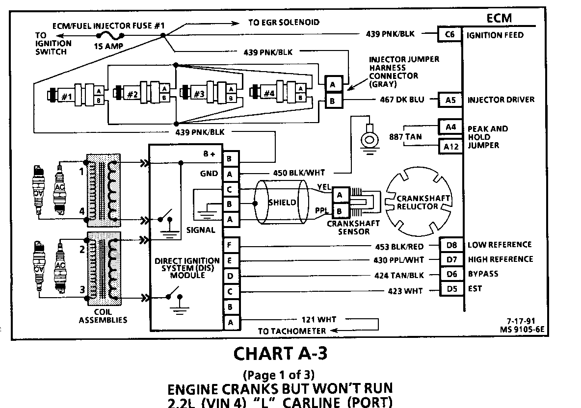
CHART A-3 (ENGINE CRANKS BUT WON'T RUN; 2.2 [VIN 4] "L" CARLINE)
Circuit Description:
Before using this chart, battery condition, engine cranking speed, and fuel quantity should be checked and verified as being OK.
Test Description: Number(s) below refer to circled number(s) on the diagnostic chart.
1. A "Service Engine Soon" light "ON" is a basic test to determine if there is battery and ignition voltage at the ECM.
No ALDL data may be the result of an ECM problem, and CHART A-2 will diagnose an ECM problem.
If TPS is less than .2 volts, the TPS 5 volt reference circuit could be shorted to ground. If TPS is over 2.5 volts, the ECM could be in the "Clear Flood Mode" which may cause the engine to not start.
The "Scan" tool should display rpm during cranking.
2. Because the DIS uses two spark plugs and cables to complete the circuit of each coil, the opposite
3. This test is performed with injectors 1, 2, 3, and 4 in parallel.
4. The Test light should flash, indicating that the ECM is controlling the injectors. How bright the light flashes is not important.
5. Ignition may have to be cycled "ON" several times to obtain maximum fuel pressure.
6. Damage to the ECM injector driver may occur if any injector resistance measures less than 11.6 ohms (internal short to ignition CKT 439).
Diagnostic Aids:
o Water or contamination in fuel system may cause a no start condition during very cold or freezing weather. The engine may start after approximately 5 minutes in a heated shop.
o An EGR valve sticking open can cause a rich air/fuel ratio during cranking. Unless the ECM enters "Clear Flood Mode" at the first indication of a flooding condition, it may result in a no start condition.
o An A/C pressure sensor with an internal short to ground can cause a no start condition. Disconnect the A/C pressure sensor, if vehicle starts replace faulty sensor.
o A MAP sensor stuck between .5 and 2.5 volts can cause a no start condition. Disconnect the MAP sensor, if vehicle starts replace faulty sensor.
LACK OF POWER, SLUGGISH OR SPONGY 2.2L (VIN 4) "J" CARLINE ---------------------------------------------------------- Definition: Engine delivers less than expected power. Little or no increase in speed when accelerator pedal is pushed down part way.
PRELIMINARY CHECKS
Perform the careful visual/physical cheeks as described at start of "Symptoms," Section "6E3-B". Compare customer's vehicle to similar unit. Make sure the customer has an actual problem. Remove air filter and check air filter for dirt, or for being plugged. Replace as necessary.
ADDITIONAL CHECKS
CHECK: ECM grounds for being clean, tight and in their proper locations. See ECM wiring diagrams. CHECK: EGR operation for being open or partly open all the time. Refer to CHART C-7. CHECK: Generator output voltage. Repair if less than 9 or more than 16 volts. CHECK: Exhaust system for possible restriction. - Inspect exhaust system for damaged or collapsed pipes. - Inspect muffler for heat distress or possible internal failure. CHECK: Torque Converter Clutch (TCC) for proper operation. Refer to SECTION 7A.
ENGINE MECHANICAL
CHECK: Engine valve timing and compression. CHECK: Engine for corrector worn camshaft. Refer to SECTION 6A.
IGNITION SYSTEM
CHECK: Proper operation of EST. Refer to "Direct Ignition System (DIS)," Section "6E3-C4". CHECK: Secondary voltage using a shop oscilloscope or a spark tester J 26792 (ST-125), or equivalent.
FUEL SYSTEM
CHECK: Restricted fuel filter. CHECK: Fuel pressure, use CHART A-7. CHECK: Contaminated fuel.
CHECK: Injector driver circuit. Disconnect all injector harness connectors at the injectors. Connect J 34730-2B Injector Test Light or equivalent 12 volts test light between the harness terminals of each injector connector and note light while cranking. If test light fails to blink at any connector, it is a faulty injector drive circuit harness, connector or terminal. Injector resistance. Measure injector resistance of each injector. Nominal resistance of each injector should be 11.6 to 12.4 ohms at 20 degrees Celcius (68 degrees Fahrenheit). Resistance will increase slightly at higher temperatures.
HESITATION, SAG, STUMBLE 2.2L (VIN 4) "J" CARLINE ------------------------------------------------- Definition: Momentary lack of response as the accelerator is pushed down. Can occur at all vehicle speeds. Usually most severe when first trying to make the vehicle move, as from a stop sign. May cause engine to stall if severe enough.
PRELIMINARY CHECKS
Perform the careful visual/physical checks as described at start of "Symptoms," Section "6E3-B".
SENSORS
CHECK: TPS - Cheek TPS for binding or sticking. Voltage should increase at a steady rate as throttle is moved toward Wide Open Throttle (WOT).
CHECK: MAP sensor output - use CHART C- 1 D.
IGNITION SYSTEM
CHECK: Fouled spark plugs or faulty secondary wiring. CHECK: Ignition system ground, CKT 453.
FUEL SYSTEM
CHECK: Fuel pressure, use CHART A-7. CHECK: Contaminated fuel.
CHECK: Evaporative Emission Control System (EECS) for proper operation. Use CHART C-3
CHECK: Injector driver circuit. Disconnect all injector harness connectors at the injectors. Connect J 34730-2B Injector Test Light or equivalent 12 volts test light between the harness terminals of each injector connector and note light while cranking. If test light fails to blink at any connector, it is a faulty injector drive circuit harness, connector or terminal. Injector resistance. Measure injector resistance of each injector. Nominal resistance of each injector should be 11.6 to 12.4 ohms at 20 degrees Celcius (68 degrees Fahrenheit). Resistance will increase slightly at higher temperatures.
ADDITIONAL CHECKS
CHECK: Service Bulletins for updates. CHECK: EGR operation, use CHART C-7. CHECK: Engine thermostat functioning correctly and proper heat range. CHECK: Generator output voltage. Repair if less than 9 or more than 16 volts.
CUTS OUT, MISSES 2.2L (VIN 4) "J" CARLINE ------------------------
Definition: Steady pulsation or jerking that follows engine speed, usually more pronounced as engine increases, not normally felt above 1500 rpm or 48 kph (30 mph). The exhaust has a steady spitting sound at idle or low speed.
FUEL SYSTEM
CHECK: Fuel system - Plugged fuel filter, low pressure. Use CHART A-7. CHECK: Contaminated fuel.
CHECK: Injector driver circuit. Disconnect all injector harness connectors at the injectors. Connect J 34730-2B Injector Test Light or equivalent 12 volts test light between the harness terminals of each injector connector and note light while cranking. If test light fails to blink at any connector, it is a faulty injector drive circuit harness, connector or terminal. Injector resistance. Measure injector resistance of each injector. Nominal resistance of each injector should be 11.6 to 12.4 ohms at 20 degrees Celcius (68 degrees Fahrenheit). Resistance will increase slightly at higher temperatures. CHECK: Perform the "Injector Balance Test." Refer to CHART C-2A.
ENGINE MECHANICAL
CHECK: Perform a cylinder compression check. If compression is low, repair as necessary. Refer to SECTION 6A.
CHECK: Base engine. Remove rocker covers. Check for bent pushrods, worn rocker arms, broken valve springs, worn camshaft lobes and valve timing. Repair as necessary. See SECTION 6A.
LACK OF POWER, SLUGGISH OR SPONGY 2.2L (VIN 4) "'L" CARLINE --------------------------------- Definition: Engine delivers less than expected power. Little or no increase in speed when accelerator pedal is pushed down part way.
PRELIMINARY CHECKS
Perform the careful visual/physical checks as described at start of "Symptoms," Section "6E3-B". Compare customer's vehicle to similar unit. Make sure the customer has an actual problem. Remove air filter and check air filter for dirt, or for being plugged. Replace as necessary.
ADDITIONAL CHECKS
CHECK: ECM grounds for being clean, tight and in their proper locations. See ECM wiring diagrams. CHECK: EGR operation for being open or partly open all the time. Refer to CHART C-7. CHECK: Generator output voltage. Repair if less than 9 or more than 16 volts. CHECK: Exhaust system for possible restriction. - Inspect exhaust system for damaged or collapsed pipes. - Inspect muffler for heat distress or possible internal failure. CHECK: Torque Converter Clutch (TCC) for proper operation. Refer to SECTION 7A.
ENGINE MECHANICAL
CHECK: Engine valve timing and compression. CHECK: Engine for correct or worn camshaft. Refer to SECTION 6A.
IGNITION SYSTEM
CHECK: For proper operation of EST. Refer to "Direct Ignition System (DIS)" Section "6E3-C4". CHECK: Secondary voltage using a shop oscilloscope or a spark tester J 26792 (ST-125), or equivalent. CHECK: Restricted fuel filter. CHECK: Fuel pressure, use CHART A-7. CHECK: Contaminated fuel.
FUEL SYSTEM
CHECK: Restricted fuel filter. CHECK: Fuel pressure, use CHART A-7. CHECK: Contaminated fuel.
CHECK: Injector driver circuit. Disconnect all injector harness connectors at the injectors. Connect J 34730-2B Injector Test Light or equivalent 12 volts test light between the harness terminals of each injector connector and note light while cranking. If test light fails to blink at any connector, it is a faulty injector drive circuit harness, connector or terminal. Injector resistance. Measure injector resistance of each injector. Nominal resistance of each injector should be 11.6 to 12.4 ohms at 20 degrees Celcius (68 degrees Fahrenheit). Resistance will increase slightly at higher temperatures.
HESITATION, SAG, STUMBLE 2.2L (VIN 4) "L" CARLINE ------------------------ Definition: Momentary lack of response as the accelerator is pushed down. Can occur at all vehicle speeds. Usually most severe when first trying to make the vehicle move, as from a stop sign. May cause engine to stall if severe enough.
PRELIMINARY CHECKS
Perform the careful visual/physical checks as described at start of "Symptoms," Section "6E3-B".
SENSORS
CHECK: TPS - Check TPS for binding or sticking. Voltage should increase at a steady rate as throttle is moved toward Wide Open Throttle (WOT). CHECK: MAP sensor output - use CHART C-lD.
IGNITION SYSTEM
CHECK: For fouled spark plugs or faulty secondary wiring. CHECK: Ignition system ground, CKT 453.
FUELSYSTEM
CHECK: Fuel pressure, use CHART A-7. CHECK: Contaminated fuel. CHECK: Evaporative Emission Control System
CHECK: Injector driver circuit. Disconnect all injector harness connectors at the injectors. Connect J 34730-2B Injector Test Light or equivalent 12 volts test light between the harness terminals of each injector connector and note light while cranking. If test light fails to blink at any connector, it is a faulty injector drive circuit harness, connector or terminal. Injector resistance. Measure injector resistance of each injector. Nominal resistance of each injector should be 11.6 to 12.4 ohms at 20 degrees Celcius (68 degrees Fahrenheit). Resistance will increase slightly at higher temperatures. CHECK: Fuel injectors. Perform injector balance test, use CHART C-2A.
ADDITIONAL CHECKS
CHECK: Service Bulletins for updates.
CHECK: EGR operation, use CHART C-7.
CHECK: Engine thermostat functioning correctly and proper heat range.
CHECK: Generator output voltage. Repair if less than 9 or more than 16 volts.
ENGINE MECHANICAL
CHECK: Perform a cylinder compression check. If compression is low, repair as necessary. Refer to SECTION 6A.
CHECK: Base engine. Remove rocker covers. Check for bent pushrods, worn rocker arms, broken valve springs, worn camshaft lobes and valve timing. Repair as necessary. See SECTION 6A.
FUEL SYSTEM
CHECK: Fuel system - Plugged fuel filter, low pressure. Use CHART A-7.
CHECK: Contaminated fuel.
CHECK: Injector driver circuit. Disconnect all injector harness connectors at the injectors. Connect J 34730-2B Injector Test Light or equivalent 12 volts test light between the harness terminals of each injector connector and note light while cranking. If test light fails to blink at any connector, it is a faulty injector drive circuit harness, connector or terminal. Injector resistance. Measure injector resistance of each injector. Nominal resistance of each injector should be 11.6 to 12.4 ohms at 20 degrees Celcius (68 degrees Fahrenheit). Resistance will increase slightly at higher temperatures.
CHECK: Perform the Injector Balance Test. Refer to CHART C-2A.


General Motors bulletins are intended for use by professional technicians, not a "do-it-yourselfer". They are written to inform those technicians of conditions that may occur on some vehicles, or to provide information that could assist in the proper service of a vehicle. Properly trained technicians have the equipment, tools, safety instructions and know-how to do a job properly and safely. If a condition is described, do not assume that the bulletin applies to your vehicle, or that your vehicle will have that condition. See a General Motors dealer servicing your brand of General Motors vehicle for information on whether your vehicle may benefit from the information.
