CAMPAIGN: STOP LAMP SWITCH INOPERATIVE

Models: 1992 Chevrolet Beretta and Corsica
TO: ALL GENERAL MOTORS DEALERS
General Motors of Canada Limited has determined that a defect which relates to motor vehicle safety exists in certain 1992 Chevrolet Beretta and Corsica model vehicles. Some of these vehicles exhibit a condition in which the service brake stoplamp switch becomes inoperative, resulting in failure of the service brake stoplamps to illuminate when the service brake pedal is actuated. If this condition occurs during three (3) consecutive service brake applications, the amber ABS (Anti- Lock Brake System) instrument panel telltale lamp may be illuminated. If the stoplamps fail to illuminate in situations where a driver in a trailing vehicle is otherwise unable to recognize a braking action in sufficient time to respond appropriately, a vehicle crash could occur without prior warning.
To prevent the possibility of this condition occurring, dealers are to replace the vehicle service brake stoplamp switch and correct the wiring in the service brake stoplamp switch wiring harness connector.
VEHICLES INVOLVED:
Involved are certain 1992 Chevrolet Beretta and Corsica model vehicles built within the following VIN breakpoints:
PLANT YEAR MODEL PLANT CODE FROM THROUGH 1992 Chevrolet Corsica and Beretta Wilmington "Y" NY100001 NY263272
All affected vehicles have been identified by the VIN listing provided to involved dealers with this bulletin. Any dealer not receiving a listing was not shipped any of the affected vehicles.
DEALER CAMPAIGN RESPONSIBILITY:
All unsold new vehicles in dealer's possession and subject to this campaign must be held and inspected/repaired per- the Service Procedure of this Campaign Bulletin before owners take possession of these vehicles.
Dealers are to perform this campaign on all involved vehicles at no charge to owners, regardless of kilometres traveled, age of vehicle, or ownership, from this time forward.
Owners of vehicles recently sold from your new vehicle inventory are to be contacted by the dealer, and arrangements made to make the required correction according to instructions contained in this bulletin.
In summary, whenever a vehicle subject to this campaign is taken into your new or used vehicle inventory, or is in your dealership for service in the future, please take the steps necessary to be sure the campaign correction has been made before selling or releasing the vehicle.
CAMPAIGN PROCEDURE:
Refer to Section 4 of the Service Policies and Procedures Manual for the detailed procedure on handling Product Campaigns. Dealers are requested to complete the campaign on all transfers as soon as possible.
OWNER NOTIFICATION:
All owners of record at the time of campaign release are shown on the attached computer listing and have been notified by first class mail from General Motors (see copy of owner letter included with this bulletin). The listings provided are for campaign activity only and should not be used for any other purpose.
PARTS INFORMATION:
Parts required to complete this campaign should be ordered through regular channels, as follows:
Part Number Description Quantity/Vehicle 10170430 Switch Assembly - Brake Stoplamp 1
PARTS AND LABOUR CLAIM INFORMATION:
Credit for the campaign work performed will be paid upon receipt of a properly completed campaign claim card or DCS transmission in accordance with the following:
Repair Code Description Time Allowance 2A Replace Stoplamp Switch and Correct Wiring .4
Time allowance includes 0.1 hour for dealer administrative detail associated with this campaign. Parts credit will be based on dealer net plus 30% to cover parts handling.
SERVICE PROCEDURE:
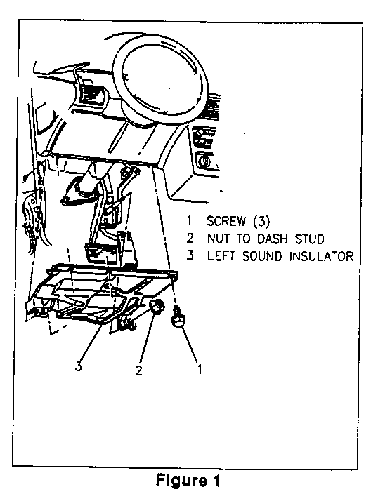
1. Remove driver's side sound insulator panel (hush panel) using a 7mm hex driver (3 screws, 1 nut). Disengage courtesy lamp socket and bulb from sound insulator panel (see Figure 1).
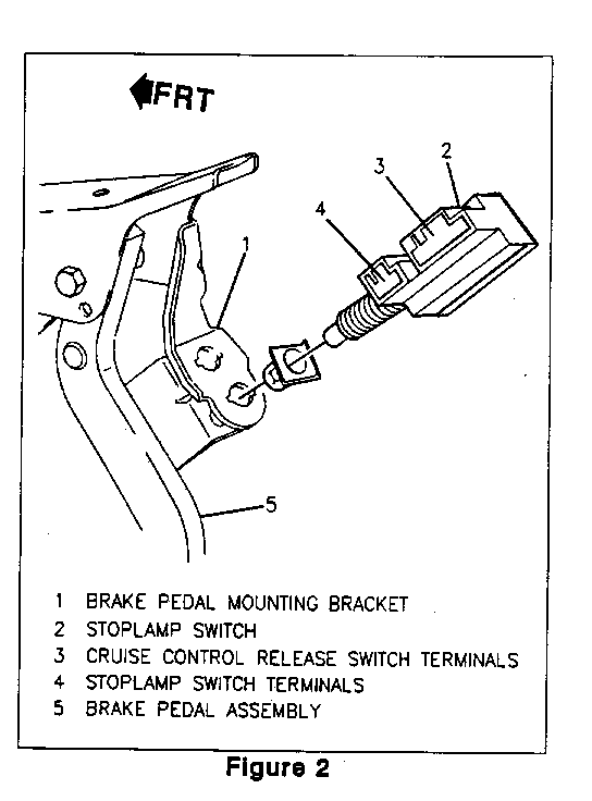
2. Disconnect stoplamp harness connector from stoplamp switch. On vehicles equipped with cruise control or automatic transaxle, disconnect cruise control/TCC connector from stoplamp switch. See Figure 2.
3. Remove stoplamp switch from plastic retainer and remove retainer from brake pedal mounting bracket. Retainer will not be reused.
4. Depress locking tangs on plastic retainer and remove retainer from brake pedal mounting brake pedal mounting Retainer will not be reused.
5. Install new stoplamp switch using the following procedure:
a) Remove new retainer from new stoplamp switch by turning retainer counter-clockwise.
b) Install new retainer into brake pedal mountin bracket making sure locking tangs are fully engaged.
c) Insert new stoplamp switch into new retainer.
d) Depress brake pedal and seat new stoplamp switch in full-forward position in plastic retainer (stoplamp switch as far forward as possible with pedal depressed).
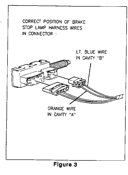
6. Inspect stoplamp harness connector for correct positioning of orange and light blue wires in connector body. The orange wire should be positioned in cavity "A" of connector and the light blue wire should be positioned in cavity "B" of connector. See Figure 3.
NOTICE: This is a correction of the information originally published in the 1992 Chevrolet Corsica/Beretta Service Manual (Book 2) on page 8A-110-0. Be certain to note this correction in all of your dealership's Corsica/Beretta Service Manuals.
7. If stoplamp harness wires are correctly positioned in the connector, proceed to step 8 of this procedure. If the wires are not correctly positioned in the connector, they must be repositioned in the connector using the following procedure:
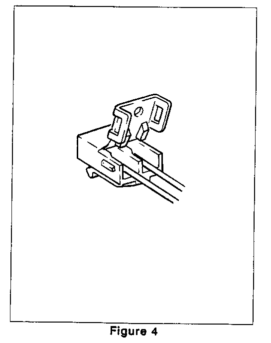
a) Open connector body (see Figure 4).
b) Carefully remove both terminals (for orange and light blue wires) from connector by using the proper size pick from the Terminal Repair Kit J-38125-A to depress the locking tangs on the terminals.
NOTICE: Never use force to remove a terminal from a connector.
c) Reform both terminal locking tangs.
d) Re-seat terminals in connector, making certain the orange wire tenninal is in cavity "A" and the light blue wire terminal is in cavity "B" (see Figure 3).
e) Close connector body.
8. Reconnect stoplamp harness to stoplamp switch.
9. On vehicles equipped with cruise control or an automatic transaxle, reconnect cruise control/TCC connector to stoplamp switch.
10. Adjust stoplamp switch by pulling upward on brake pedal. This will result in the stoplamp switch "ratcheting" through the retainer on the stoplamp switch bracket.
Proper switch adjustment is achieved when:
- No clicks are heard when pedal is pulled upward, and - Stoplamps do not stay on without brake application.
11. Check for proper stoplamp operation by depressing and releasing the brake pedal while an observer watches for stoplamp illumination.
12. Reinstall courtesy lamp socket and bulb to sound insulator panel.
13. Reinstall sound insulator panel (hush panel) using a 7mm hex driver (3 screws, 1 nut). Torque until snug and tight.
14. Install Campaign Identification Label.
INSTALLATION OF CAMPAIGN IDENTIFICATION LABEL
Clean surface of radiator upper mounting panel and apply a Campaign Identification Label. Make sure the correct campaign number is inserted on the label. This will indicate that the campaign has been completed.
General Motors of Canada bulletins are intended for use by professional technicians, NOT a "do-it- yourselfer." They are written to inform these technicians of conditions that may occur on some vehicles, or to provide information that could assist in the proper service of a vehicle. Properly trained technicians have the equipment, tools, safety instructions, and know-how to do a job properly and safely. If a condition is described, DO NOT assume that the bulletin applies to your vehicle, or that your vehicle will have that condition. See your General Motors dealer for information on whether your vehicle may benefit from the information.
Dear General Motors Customer:
General Motors of Canada Limited has determined that a defect which relates to motor vehicle safety exists in certain 1992 Chevrolet Beretta and Corsica model vehicles. Some of these vehicles exhibit a condition in which the service brake stoplamp switch becomes inoperative, resulting in failure of the service brake stoplamps to illuminate when the service brake pedal is actuated. If this condition occurs during three (3) consecutive service brake applications, the amber ABS (Anti- Lock Brake System) instrument panel telltale lamp may be illuminated. If the stoplamps fail to illuminate in situations where a driver in a trailing vehicle is otherwise unable to recognize a braking action in sufficient time to respond appropriately, a vehicle crash could occur without prior warning.
To prevent the possibility of this condition occurring on your vehicle, your dealer will replace the service brake stoplamp switch and correct the wiring in the service brake stoplamp switch harness for your vehicle.
This service will be provided for you at no charge.
Please contact your GM dealer as soon as possible to arrange a service date.
If parts are required, ask your dealer for details regarding their availability. If parts are not in stock, they can be ordered before scheduling your service date.
This letter identifies your vehicle. Presentation of this letter to your dealer will assist their Service personnel in completing the necessary correction to your vehicle in the shortest possible time.
We are sorry to cause you this inconvenience; however, we have taken this action in the interest of your continued satisfaction with our products.


General Motors bulletins are intended for use by professional technicians, not a "do-it-yourselfer". They are written to inform those technicians of conditions that may occur on some vehicles, or to provide information that could assist in the proper service of a vehicle. Properly trained technicians have the equipment, tools, safety instructions and know-how to do a job properly and safely. If a condition is described, do not assume that the bulletin applies to your vehicle, or that your vehicle will have that condition. See a General Motors dealer servicing your brand of General Motors vehicle for information on whether your vehicle may benefit from the information.
