MULTI-POINT FUEL INJECTION SYSTEM (SERVICE INFORMATION)

SUBJECT: FUEL SYSTEM SERVICE INFORMATION
VEHICLES AFFECTED: 1992 "J" AND "L" CARS WITH LN2 (2.2L) MULTI-POINT FUEL INJECTION SYSTEM
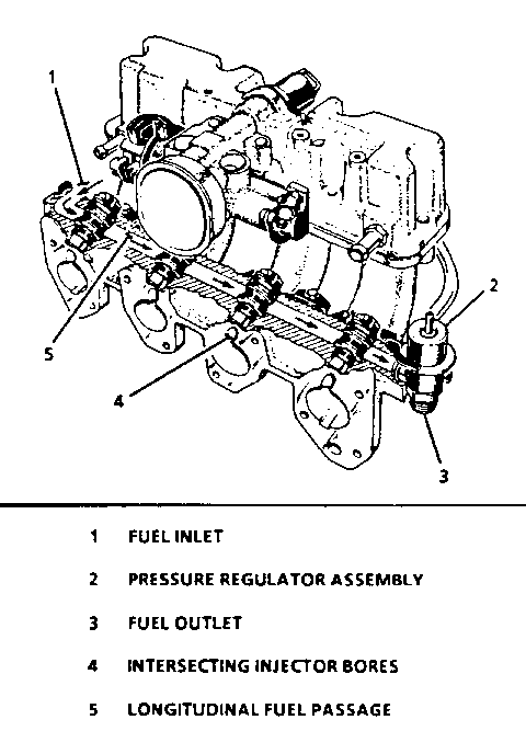
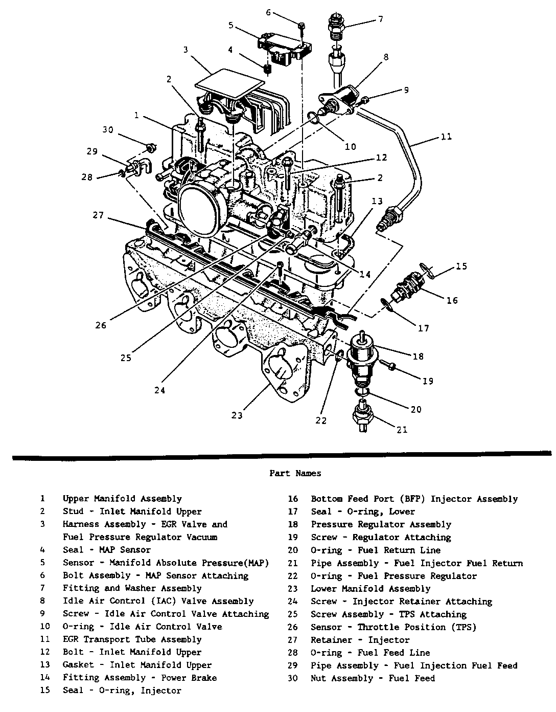
Beginning with the 1992 model Year the 2.2L engine has been upgraded to include a Multi-point fuel injection system. This particular fuel injection system is unique to the 2.2L engine within General Motors. The 2.2L engine has integrated the fuel rail that supplies fuel to the fuel injectors with the intake manifold (see Figure 1). The following procedures MUST be followed when servicing the 2.2L engine.
(Note: 1. Before servicing fuel related components relieve fuel system pressure. 2. When re-installing fuel injectors verify that only one lower O-Ring is installed, and the old O-Ring is not in the lower manifold. 3. Remove the spark plug and crank the engine after servicing the fuel injectors to verify that the engine is not hydra-locked with fuel from a leaking injector.)
1. Before performing engine noise evaluations be sure to become familiar with the normal audible noise (ticking) level of the fuel injectors at several engine speeds. The audible noise of the fuel injectors is most prominent when the engine is at idle and the hood is raised. The fuel injectors contribution to the total engine noise will tend to decrease at higher engine speeds. Once you have become familiar with the noise associated with the fuel injectors you may proceed to investigate any customer comments of engine noise using established procedures. If the noise is diagnosed as fuel injectors then compare the vehicle with other vehicles of the same type. Keep in mind that the total fuel injector noise will vary slightly from car to car but, any large difference may indicate a problem.
2. The 2.2 Liter engine in addition to integrating the fuel rail with the intake manifold has also integrated the air inlet (fitted with a throttle valve), throttle position switch, idle air control valve, throttle cam housing, and vacuum ports in the upper assembly portion of the intake manifold. This eliminated having a separate bolt on throttle body unit. The lower portion of the intake manifold incorporates the fuel rail and allows for the mounting of the fuel injectors and the fuel pressure regulator assembly.
3. The following procedures are to be used when servicing the 2.2L engine.
CAUTION:
TO REDUCE THE RISK OF FIRE AND PERSONAL INJURY, RELIEVE THE FUEL SYSTEM PRESSURE BEFORE SERVICING FUEL SYSTEM COMPONENTS.
AFTER RELIEVING SYSTEM PRESSURE, A SMALL AMOUNT OF FUEL MAY BE RELEASED WHEN SERVICING FUEL LINES OR
CONNECTIONS: TO REDUCE THE CHANCE OF PERSONAL INJURY, COVER REGULATOR AND FUEL LINES WITH A SHOP TOWEL BEFORE DISCONNECTING, TO CATCH ANY FUEL THAT MAY LEAK OUT. PLACE THE TOWEL IN AN APPROVED CONTAINER WHEN DISCONNECT IS COMPLETE.
Fuel System Pressure Relief Procedure
1. Loosen fuel filler cap to relieve tank pressure (do not tighten at this time). 2. Remove fuel pump fuse. (J-car) Raise vehicle. (L-car). 3. Disconnect fuel pump electrical connector. (L-car) 4. Lower vehicle. (L-car) 5. Start engine and run until fuel supply remaining in fuel pipes is consumed. Engage starter for 3.0 seconds to assure relief of any remaining pressure. 6. Install fuel pump fuse. (J-car) Raise vehicle. (L-car) 7. Connect fuel pump electrical connector. (L-car) 8. Lower vehicle. (L-car) 9. Disconnect negative battery terminal to avoid possible fuel discharge if an accidental attempt is made to start the engine.
Upper Manifold Assembly
Remove or Disconnect
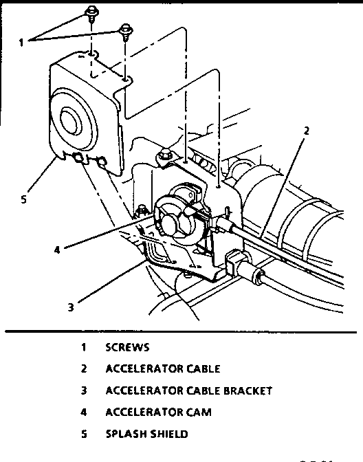
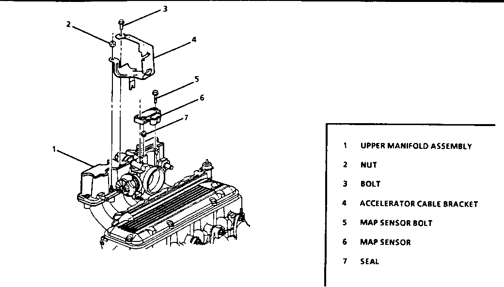
1. Negative Battery cable. 2. Air intake duct. 3. Accelerator cable splash shield from accelerator cable bracket refer to Figure 2. 4. Accelerator, cruise and transmission control cables. 5. Vacuum hose harness from top of air inlet. 6. Disconnect PCV and power brake vacuum hoses from vacuum tubes at upper manifold. * Position vacuum hoses out of the way. 7. Electrical connectors at MAP sensor, TPS, and IAC valve Refer to Figure 3. 8. Bolts/nuts attaching throttle cable bracket. * Position bracket and cables out of the way. 9. Bolts/studs attaching upper manifold to lower manifold. * Position EGR and injector wiring harness out of the way.
10. Upper manifold assembly and gasket. * Discard gasket, do not attempt to re-use gasket.
NOTICE: USE EXTREME CARE WHEN CLEANING OLD GASKET MATERIAL FROM MACHINED ALUMINUM SURFACES. SHARP TOOLS MAY DAMAGE SEALING SURFACES.
11. Clean all gasket sealing surfaces.
Install or Connect * Position EGR valve injector so that the port faces directly toward the throttle bore.
1. New upper manifold gasket.
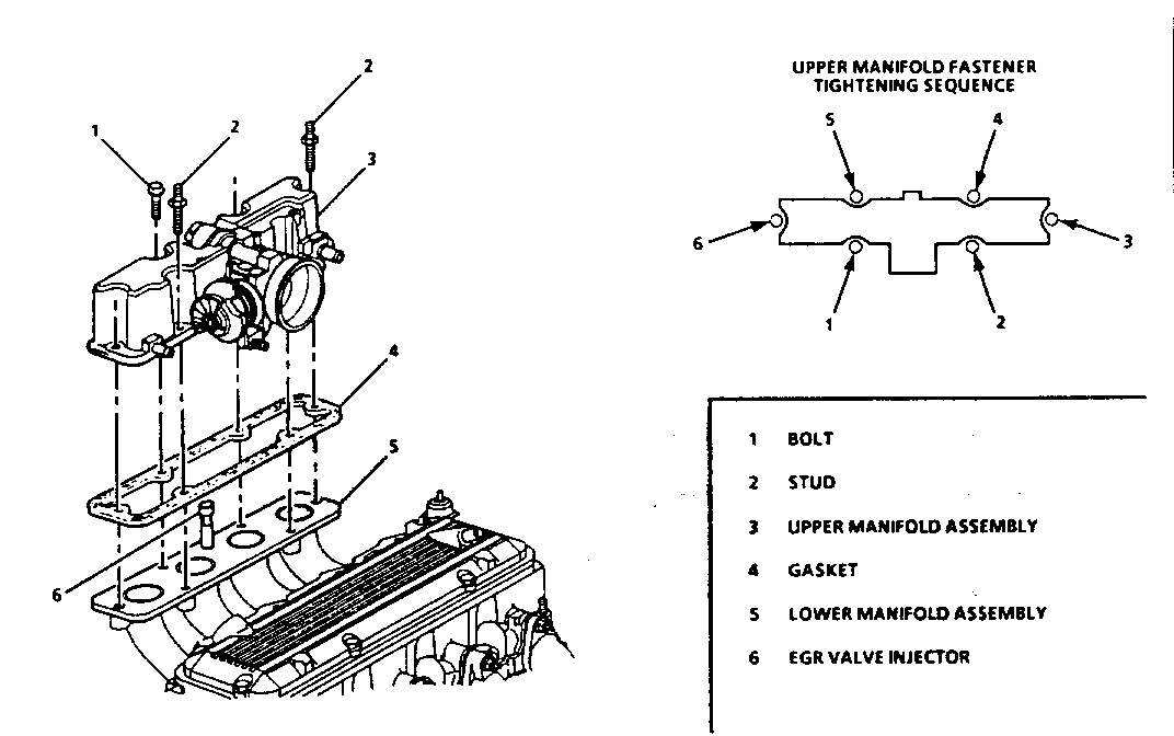
2. Upper manifold assembly Refer to Figure 4 * Reposition EGR and injector wiring harness.
3. Upper manifold attaching bolts/studs. * Tighten upper manifold bolts/studs to 30.0 N.m (22 ft.lbs.).
4. Accelerator cable bracket with attaching bolts/nuts. * Finger tighten only at this time.
NOTICE: THE ACCELERATOR BRACKET MUST BE ALIGNED WITH THE ACCELERATOR CAM TO PREVENT CABLE WEAR, WHICH COULD RESULT IN CABLE BREAKAGE.
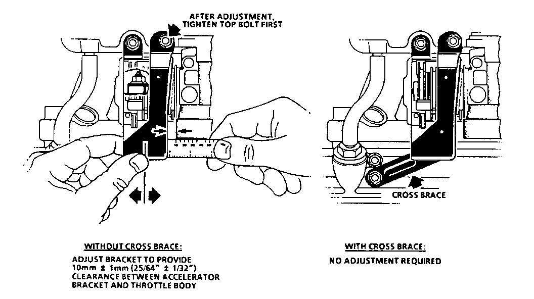
A. Place a steel rule across bore of throttle body, with one end in contact with accelerator bracket.
B. Adjust accelerator bracket to obtain a 10 mm +/- 1 mm (25/64 +/- 1/32) gap between bracket and throttle body Refer to Figure 5.
C. Tighten top bolt first.
D. Tighten accelerator cable bracket bolts/nuts to 25 N.m (18 ft. lbs.).
5. Accelerator, cruise and transmission control cables.
6. Splash shield to accelerator bracket.
7. Electrical connectors to MAP sensor, TPS, IAC valve and EGR vacuum solenoid.
8. Vacuum hose harness to top of air inlet.
9. Connect PCV and power brake vacuum hoses to vacuum tubes at upper manifold.
10. Negative battery cable. * Turn ignition switch to the "ON" position for two seconds, then turn to the "OFF" position for ten seconds. Again turn to the "ON" position, and check for fuel leaks.
11. Air intake duct.
PRESSURE REGULATOR ASSEMBLY
Remove or Disconnect
1. Relieve fuel system pressure. * Refer to "Fuel System Pressure Relief Procedure".
2. Disconnect negative battery cable.
3. Remove vacuum hose from regulator. * Refer to CAUTION statement.
4. Fuel return pipe clamp.
5. Fuel return pipe and 0-ring from regulator. * Discard 0-ring.
6. Pressure regulator bracket attaching screw.
7. Pressure regulator assembly and 0-ring. * Discard 0-ring.
Install or Connect
1. Lubricate new pressure regulator 0-ring with clean engine oil, then install on pressure regulator.
2. Pressure regulator assembly onto manifold.
3. Pressure regulator bracket attaching screw coated with Loctite 262 or equivalent.
* Tighten pressure regulator bracket attaching screw to 3.5 N.m (31 in.lbs.)
4. Vacuum hose to regulator.
5. Lubricate new fuel return pipe 0-ring with clean engine oil, then install on end of pipe.
6. Fuel return pipe to pressure regulator. * Tighten fuel return pipe attaching nut to 30 N.m (22 in.lbs.).
7. Fuel return pipe clamp attaching nut to lower manifold assembly.
8. Tighten fuel filler cap.
9. Negative battery terminal * Turn ignition switch to the "ON" position for two seconds, then turn to the "OFF" position for ten seconds. Again, turn to the "ON" position, and check for fuel leaks.
BOTTOM FEED PORT FUEL INJECTORS
NOTICE: ALWAYS REMOVE THE FUEL PRESSURE REGULATOR TO DRAIN EXCESS FUEL AND TO PREVENT FUEL FROM ENTERING ENGINE CYLINDERS, WHEN INJECTORS ARE REMOVED FOR SERVICE. FLOODED CYLINDERS COULD RESULT IN ENGINE DAMAGE.
USE CARE IN REMOVING INJECTORS TO PREVENT DAMAGE TO THE ELECTRICAL CONNECTOR PINS ON THE INJECTOR, AND THE NOZZLE. THE FUEL INJECTOR IS SERVICED AS A COMPLETE ASSEMBLY ONLY. SINCE THIS IS AN ELECTRICAL COMPONENT, DO NOT SOAK IN CLEANER.
Remove or Disconnect
1. Relieve fuel system pressure. * Refer to "Fuel System Pressure Relief Procedure."
2. Disconnect negative battery cable.
3. Upper Manifold Assembly. * Refer to "Upper Manifold Assembly."
CAUTION:
TO REDUCE THE CHANCE OF PERSONAL INJURY, COVER REGULATOR AND FUEL LINE FITTINGS WITH A SHOP TOWEL BEFORE DISCONNECTING, TO CATCH ANY FUEL THAT MAY LEAK OUT. PLACE THE TOWEL IN AN APPROVED CONTAINER AFTER DISCONNECT IS COMPLETED.
4. Pressure regulator assembly. * Refer to "Pressure Regulator Assembly."
NOTICE: TO PREVENT DAMAGE TO INJECTOR RETAINING BRACKET AND/OR INJECTORS, DO NOT TRY TO REMOVE INJECTORS BY LIFTING UP THE INJECTOR RETAINING BRACKET WHILE INJECTORS ARE STILL INSTALLED IN BRACKET SLOTS.
* DO NOT ATTEMPT TO REMOVE BRACKET WITHOUT FIRST REMOVING FUEL PRESSURE REGULATOR.
5. Injector retainer bracket attaching screws.
6. Injector retainer bracket. * Carefully slide bracket off to clear injector slots and regulator.
7. Electrical injector connector(s).
CAUTION:
TO REDUCE THE RISK OF FIRE AND PERSONAL INJURY, VERIFY THAT THE LOWER (SMALL) O-RING OF EACH INJECTOR DOES NOT REMAIN IN THE LOWER MANIFOLD. IF THE O-RING IS NOT REMOVED WITH THE INJECTOR, THE REPLACEMENT INJECTOR, WITH THE NEW O-RINGS, WILL NOT SEAT PROPERLY IN THE INJECTOR SOCKET, AND COULD CAUSE A FUEL LEAK.
8. Fuel injector(s) * Discard 0-ring seals. * Cover injector sockets to prevent dirt and other contaminants from entering open fuel passages.
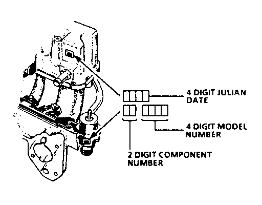
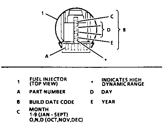
IMPORTANT: Each injector is calibrated for a specific flow rate. When replacing fuel injectors, order replacements with the identical part number as the old injectors. Refer to Figure 7.
Install or Connect
1. Lubricate new injector 0-ring seals with clean engine oil, and install on injector assembly. * See "CAUTION" statement above.
2. Bottom Feed Port injector assembly into lower manifold injector socket, with electrical connectors facing inward.
3. Injector retainer bracket. * Carefully install bracket so that injector retaining slots and regulator are aligned with bracket slots.
4. Electrical injector connectors.
5. Pressure Regulator Assembly * Refer to "Pressure Regulator Assembly."
6. Injector retainer bracket attaching screws.
* Use Loctite 262 or equivalent threadlocker.
* Tighten injector retainer bracket attaching screws to 3.5 N.m (31 in.lbs.).
7. Upper Manifold Assembly. * Refer to "Upper Manifold Assembly."
8. Tighten fuel filler cap.
9. Negative battery terminal. * Turn ignition switch to the "ON" position for two seconds, then turn to the "OFF" position for ten seconds. Again turn to the "ON" position, and check for fuel leaks.
CAUTION:
BE SURE THAT NONE OF THE ENGINE CYLINDERS HAS FILLED WITH GASOLINE DURING THE SERVICE PROCEDURE DUE TO LEAKAGE FROM THE FUEL SYSTEM INTO THE CYLINDER, AS THIS COULD DAMAGE THE ENGINE IF A STARTING ATTEMPT WERE MADE.
10. Air intake duct.
Use Applicable Labour Operation and Time
General Motors bulletins are intended for use by professional technicians, not a "do-it-yourselfer". They are written to inform those technicians of conditions that may occur on some vehicles, or to provide information that could assist in the proper service of a vehicle. Properly trained technicians have the equipment, tools, safety instructions and know-how to do a job properly and safely. If a condition is described, do not assume that the bulletin applies to your vehicle, or that your vehicle will have that condition. See a General Motors dealer servicing your brand of General Motors vehicle for information on whether your vehicle may benefit from the information.
