SERVICE MANUAL UPDATE SEC. 6E3 REV. TORQUE SPECS, MAP/EGR/PCV

SUBJECT: SERVICE MANUAL UPDATE - SECTION 6E3 - REVISED TORQUE SPECS-MAP SENSOR-EGR SOLENOID-PCV VALVE COVER
VEHICLES AFFECTED: 1992 "J, L" 2/2L (VIN 4)
This Bulletin applies to 1992 2.2L (VIN 4) engines found in "J" and "L" Carline Service Manuals.
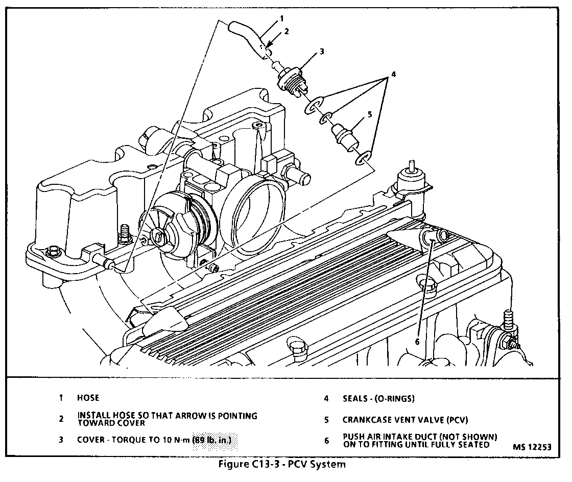
The information contained in this Bulletin cancels and supersedes Page 6E3-C7-3 (Driveability and Emissions-PFI), Exhaust Gas Recirculation (EGR) system and Figure C13-3 on Page 6E3-C13-2 (Driveability and Emissions-PFI), Positive Crankcase Ventilation (PCV) system.
Revised Torque Specifications are highlighted on the revised pages.
ON-VEHICLE SERVICE
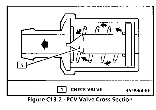
See Figure C13-3 for replacement of PCV system components.
An engine which is operated without any crankcase ventilation can be damaged. Therefore, it is important to replace the PCV valve and at intervals shown in SECTION OB.
Periodically, inspect the hoses and clamps and replace any showing signs of deterioration.
PARTS INFORMATION
PART NAME GROUP --------- ----- Valve Asm, Cr/Case Vent . . . . . . . . .1.745
ON-VEHICLE SERVICE
EGR VALVE
Remove or Disconnect
1. EGR valve vacuum tube at valve. 2. Bolts. 3. EGR valve from manifold.
EGR Manifold Passage
Inspect
- If EGR passages in the inlet manifold indicate excessive build-up of deposits, the passages should be cleaned. Care should be taken to ensure that all loose particles are completely removed to prevent them from clogging the EGR valve or from being ingested into the engine.
- Do not wash EGR valve in solvents or degreaser-- permanent damage to valve diaphragm may result. Also, sand blasting of the valve is not recommended since this can affect the operation of the valve.
Clean
1. With a wire wheel, buff the exhaust deposits from the mounting surface and around the valve.
2. Look for exhaust deposits in the valve outlet. Remove deposit build-up with a screwdriver.
3. Clean mounting surfaces of intake manifold and valve assembly.
Install or Connect
1. EGR valve using new gasket. 2. Bolts and tighten to 15-30 N.m (11-22 lb. ft.). 3. Vacuum line to valve.
EGR CONTROL SOLENOID
Remove or Disconnect
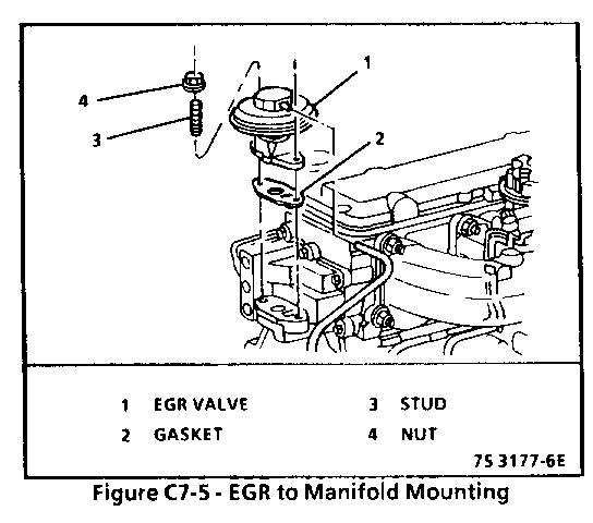
1. Negative battery cable. 2. MAP sensor. 3. Electrical connector at solenoid (see Figure C7-5). 4. Screw and solenoid. 5. Vacuum hoses.
Install or Connect
1. Solenoid and bracket, tighten screw to 30 N.m (22lb. ft.).
2. Vacuum hoses.
3. Electrical connector.
4. Position seal into manifold assembly halfway, insert MAP sensor nipple into seal, seat sensor fully into seal and onto mounting surface.
5. MAP sensor screws, tighten screws to 3 N.m (27 lb. in.). DO NOT OVER TORQUE!
6. Negative battery cable.
PARTS INFORMATION
PARTS NAME GROUP ---------- ----- Valve, EGR . . . . . . . . . . . . . . . . . . . . 3.670 Gasket, EGR Valve . . . . . . . . . . . . . . . . . . . . 3.680 Control, EGR Vacuum . . . . . . . . . . . . . . . . . . . . 3.670


General Motors bulletins are intended for use by professional technicians, not a "do-it-yourselfer". They are written to inform those technicians of conditions that may occur on some vehicles, or to provide information that could assist in the proper service of a vehicle. Properly trained technicians have the equipment, tools, safety instructions and know-how to do a job properly and safely. If a condition is described, do not assume that the bulletin applies to your vehicle, or that your vehicle will have that condition. See a General Motors dealer servicing your brand of General Motors vehicle for information on whether your vehicle may benefit from the information.
