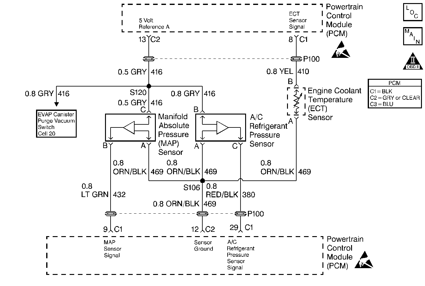
Circuit Description
The Powertrain Control Module (PCM) uses the manifold absolute pressure (MAP) sensor to control the fuel delivery and the ignition timing. The MAP sensor measures the changes in the intake manifold pressure which results from engine load, or intake manifold vacuum, and the RPM changes, and converts these into voltage outputs. The Powertrain Control Module (PCM) sends a 5 volt reference voltage to the MAP sensor. As the manifold pressure changes, the output voltage of the MAP sensor also changes. By monitoring the MAP sensor output voltage, the PCM knows the manifold pressure. A lower pressure, or low voltage, output voltage will be approximately 1.0 to 1.5 volts at idle. Higher pressures, or higher voltage, output voltage will be approximately 4.5 to 4.8 volts at wide open throttle (WOT). The MAP sensor is also used to measure barometric pressure, allowing the PCM to make adjustments for different altitudes.
Conditions for Setting the DTC
- Engine speed is stable 150 RPM.
- Idle Air Control (IAC) is stable 10 counts.
- Throttle Position (TP) is stable 1 %.
- No Exhaust Gas Recirculation (EGR) valve position change.
- Above conditions met for 0.4 seconds.
- Manifold Absolute Pressure (MAP) changes more than 0.33 V in 15.6 ms.
- DTC(s) P0107 or P0108 are not set.
Action Taken When the DTC Sets
| • | The Malfunction Indicator Lamp (MIL) will illuminate. |
| • | The Powertrain Control Module (PCM) will record operating conditions at the time the diagnostic fails. This information will be stored in the Freeze Frame and Failure Records buffers. |
| • | A history DTC is stored. |
| • | Coolant fan turns ON. |
| • | The PCM will substitute a fixed MAP value and use Throttle Position (TP) to control the fuel delivery (scan tool will not show defaulted value.) |
| • | The vehicle will operate in Open Loop when the vehicle is under 8 km/h (5 mph). The vehicle will operate in Closed Loop when the vehicle is over 8 km/h (5 mph). |
Conditions for Clearing the MIL/DTC
| • | The MIL will turn OFF after three consecutive ignition cycles in which the diagnostic runs without a fault. |
| • | A history DTC will clear after 40 consecutive warm-up cycles without a fault. |
| • | The MIL/DTCs can be cleared by using the scan tool. |
Diagnostic Aids
With the ignition ON and the engine stopped, the manifold pressure is equal to atmospheric pressure and the signal voltage will be high. This information is used by the PCM as an indication of the vehicles altitude. Comparison of this reading with a known good vehicle with the same sensor is a good way to check the accuracy of a suspected sensor. Readings should be the same 0.4 volts.
Test Description
Number(s) below refer to step number(s) on the Diagnostic Table.
-
The Powertrain OBD System Check prompts the technician to complete some basic checks and store the freeze frame and failure records data on the scan tool if applicable. This creates an electronic copy of the data taken when the fault occurred. The information is then stored on the scan tool for later reference.
-
Output changes greater than 6.3 kPa verify if the fault is present now.
-
This step simulates DTC P0107. If the PCM recognizes the change, the PCM and CKT 416 and CKT 432 are OK. If CKT 469 is faulty, the A/C system may also be inoperative and a DTC P0530 may also be set
-
Output changes greater than 6.3 kPa indicate a possible faulty connector or connection, a cracked vacuum hose or faulty sensor that is internally affected from the twisting motion of this step.
-
Check terminals for being backed out, improper mating, broken locks, improperly formed or damaged terminals, poor terminal to wiring connections or physical damage to the wiring harness.
-
Because the MAP sensor is very sensitive to pressure change, it must have its own vacuum source or it may detect pressure changes due to other devices using the same source.
Step | Action | Value(s) | Yes | No | ||||||
|---|---|---|---|---|---|---|---|---|---|---|
Was the Powertrain On-Board Diagnostic (OBD) System Check performed? | -- | |||||||||
With the engine idling, install a scan tool. Does the scan tool display a MAP kPa varying more than the specified value? | 6.3 kPa | |||||||||
Does the scan tool display a steady MAP voltage of the specified voltage or less? | 1.0 V | |||||||||
With the engine still idling, twist the MAP sensor electrical connector by hand (only). | 6.3 kPa | |||||||||
Inspect the MAP sensor and the PCM electrical connector terminals for poor connections, proper contact tension or poor terminal to wire connection. Was a problem found? | -- | |||||||||
6 | Inspect the PCM electrical connector terminals for the following conditions:
Was a problem found? | -- | ||||||||
7 |
Does the scan tool display a MAP kPa varying more than the specified value? | 6.3 kPa | Go to Diagnostic Aids | |||||||
8 | Repair the connector terminal(s) as necessary. Is the action complete? | -- | -- | |||||||
Is the vacuum source OK? | -- | |||||||||
10 | Replace the MAP sensor. Is the action complete? | -- | -- | |||||||
11 | Repair the vacuum source. Is the action complete? | -- | -- | |||||||
12 | Replace the PCM. Is the action complete? | -- | -- | |||||||
13 |
Does the scan tool indicate that this diagnostic ran and passed? | -- | ||||||||
14 | Check if any additional DTCs are set. Are any DTCs displayed that have not been diagnosed? | -- | Go to Applicable DTC Table | System OK |
