Diagnosis
Use the following scan tool parameters when diagnosing this circuit.
| • | KS Noise Channel - This is used to monitor the input signal from the knock sensor. This position should display YES when knock is being detected and NO when no knock is being detected. |
| • | KS Retard - This indicates how many degrees the PCM is retarding the spark timing. |
| • | KS Activity Counter. - This displays the varying AC signal from the knock sensor. The scan tool will display KS activity in counts. The KS activity counter indicates if the PCM is receiving the varying frequency output of the knock sensor. The counter increases with engine speed. |

Circuit Description
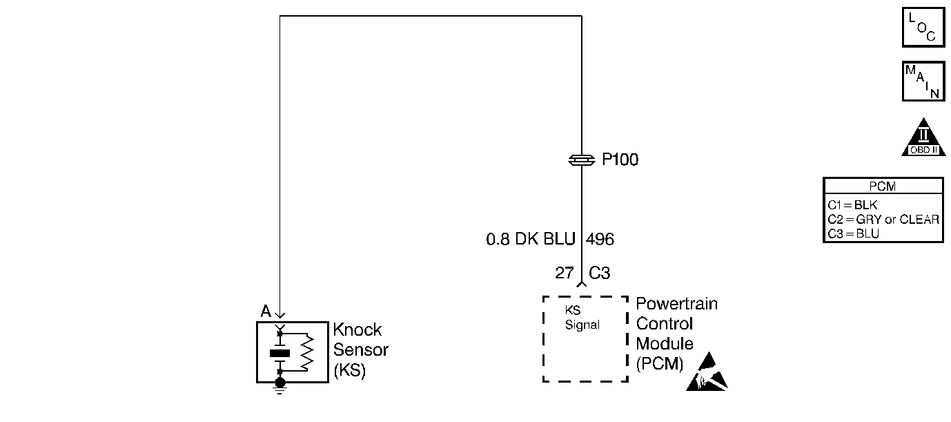
The Knock Sensor (KS) detects abnormal vibration (spark knocking) in the engine. The sensor is mounted in the engine block near the cylinders. The sensor produces an AC output voltage which increases with the severity of the knock. The amplitude and the frequency are dependent upon the knock level. The knock sensor sends this signal voltage to the Powertrain Control Module (PCM). The PCM will retard the electronic spark timing based on the signal the PCM receives in order to reduce the spark knock.
Diagnostic Aids
| • | This table does not check for an open knock sensor signal circuit. If the knock sensor signal circuit is open, a DTC P0325 will be set. |
| • | While observing the knock signal on the scan tool, there should be an indication that knock is present whenever detonation can be heard. Detonation is most likely to occur under high engine load conditions. |
Test Description
Number(s) below refer to number(s) on the diagnostic table.
-
The Powertrain OBD System Check prompts the technician to complete some basic checks and store the freeze frame and failure records data on the scan tool if applicable. This creates an electronic copy of the data taken when the fault occurred. The information is then stored on the scan tool for later reference. If a DTC P0325 is set, do not use this table.
-
With the engine idling, there should be not be a knock signal present because detonation is not likely under a no load condition.
-
If the engine has an internal problem which is creating a knock, the knock sensor may be responding to the mechanical noise.
-
Tapping on the engine near the sensor simulates a knock. This step determines if the sensor can respond to an engine noise.
-
The sensor will not produce any voltage unless a knock is present. Voltage present at the sensor indicates that the sensor is faulty.
-
This step will determine if the reason the knock sensor did not respond to the tapping was due to a faulty sensor, KS module or PCM.
-
If the knock sensor signal circuit is routed to close to ignition circuitry, the circuit may be picking up induced electrical noise causing a false knock signal.
-
Refer to Powertrain Control Module/EEPROM Replacement/Programming for KS module replacement.
-
Replacement PCM's must be reprogrammed. Refer to the latest Techline information for programming procedures.
Step | Action | Value(s) | Yes | No |
|---|---|---|---|---|
Was the Powertrain On-Board Diagnostic (OBD) System Check performed? | -- | |||
Is spark knock indicated? | -- | |||
Listen for engine knock while increasing and decreasing the engine speed. Is an engine knock present? | -- | |||
|
Caution: Avoid contact with moving parts and hot surfaces while working around a running engine in order to prevent physical injury. Tap on the engine block near the knock sensor. Is spark knock indicated? | -- | |||
Is an AC voltage indicated? | -- | |||
Is an AC voltage indicated while tapping near the sensor? | -- | |||
Check the knock sensor signal circuit routing and repair as necessary. Was a repair necessary? | -- | |||
8 | Repair the basic engine problem. Is the action complete? | -- | -- | |
9 | Replace the knock sensor. Is the action complete? | -- | -- | |
10 | Was the KS module replaced? | -- | ||
Replace the KS module. Is the action complete? | -- | -- | ||
Replace the PCM. Is the action complete? | -- | -- | ||
13 | Operate vehicle within the conditions under which the original symptom was noted. Does the system now operate properly? | -- | System OK Refer to Diagnostic Aids |
