INOP. REAR HATCH DEFOGGER ELECTRICAL CIRCUIT REVISION

VEHICLES AFFECTED: 1984 Corvette
Some comments have been received regarding blown fuses in the 1984 Corvette rear hatch defogger circuit. This circuit also feeds the door mirror glass heaters. Under certain conditions, the current draw in the feed circuit may exceed 30 amps resulting in a blown fuse.
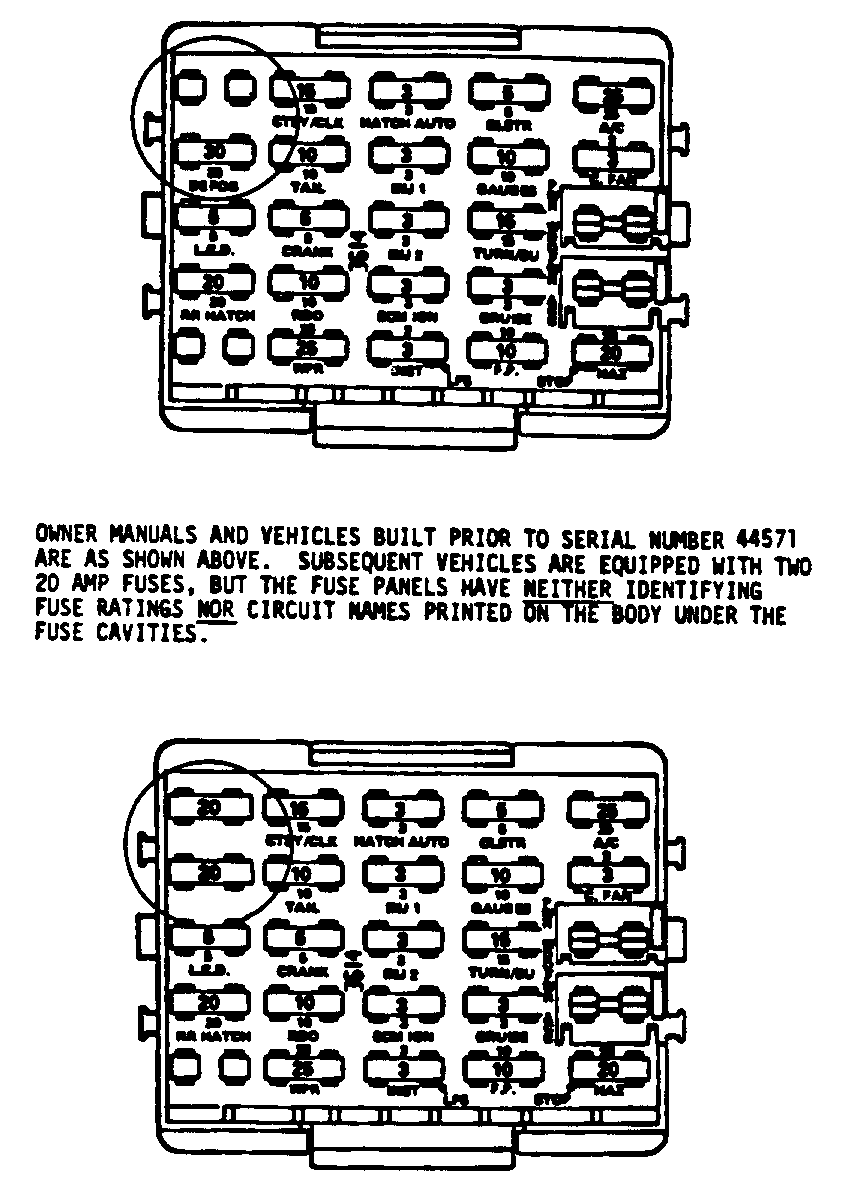
This condition has been corrected, starting with vehicle number E5144571, by replacing the (1) 30 amp fuse labeled 'defog' in the fuse block with (2) 20 amp fuses in parallel. These fuses are locdted in the two (2) top left hand cavities of the fuse block (see the two (2) views of the fuse block).
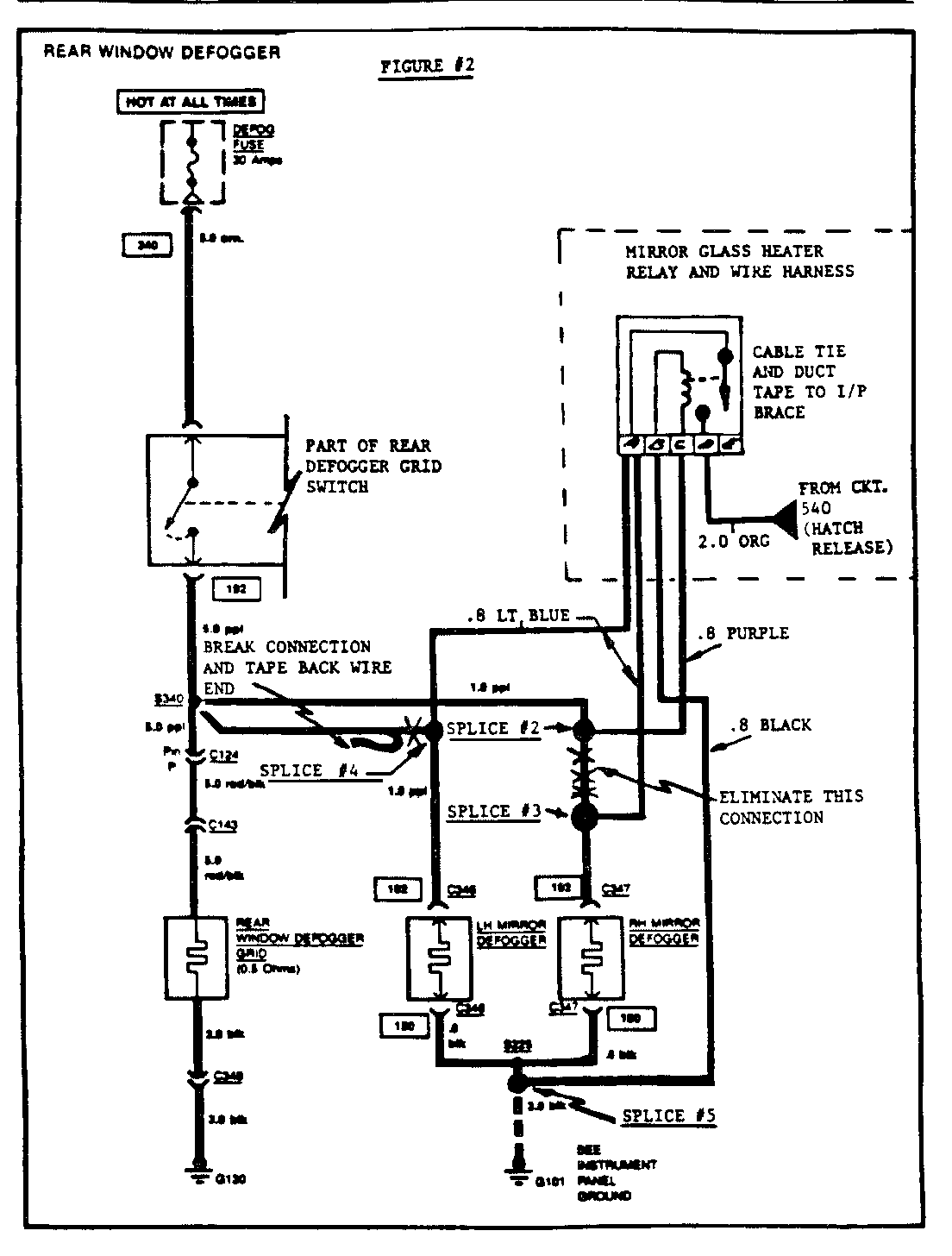
On vehicles built prior to serial number E5144571, the 30 amp load is the maximum allowable current on the defogger circuit. It has been decided to remove the side door mirror glass heater high current load from the defogger circuit and move it to the rear hatch release feed circuit (see Figures no. 2 and no. 3).
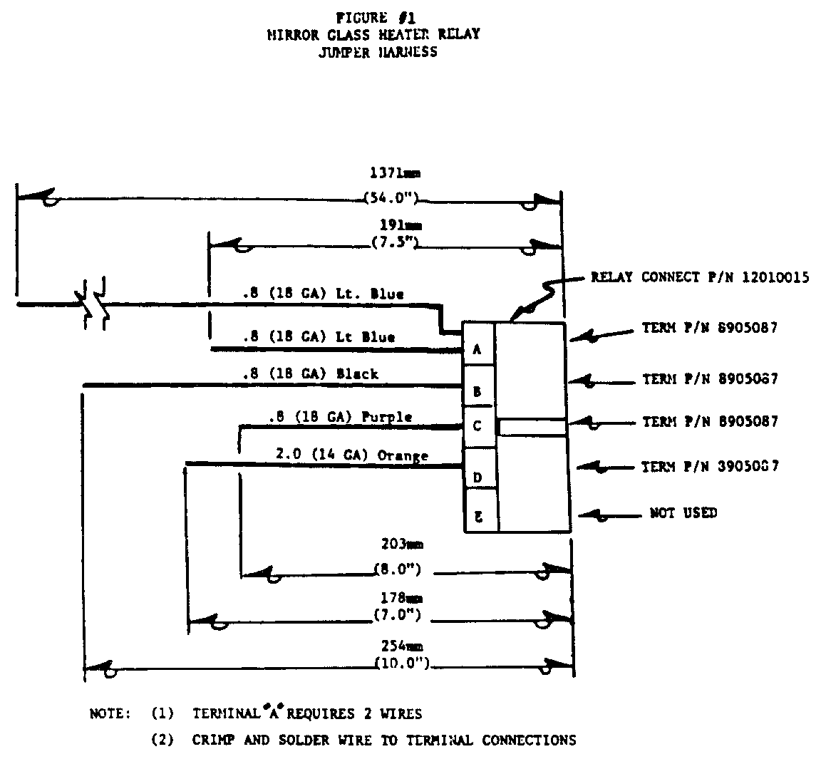
In order to accomplish this 'load' change and retain normal operation of the defogger switch, a relay and wiring jumper harness has to be installed. (see Figure No. 1).
The following parts list and procedure steps are required to perform this installation.
PARTS LIST
QUANTITY P/N DESCRIPTION -------- --- ---------- 1 14078902 Relay Assembly 1 12010015 Connector, Relay 4 8905087 Terminal 5 ft. (1.5 m) NPN (18 ga.) Lt. Blue Electrical Wire 10 In. (25.5 cm) NPN (18 gd.) Black Electrical Wire 8 In. (20 cm) NPN (18 ga.) Purple Electrical Wire 9 In. (23 cm) NPN (14 gd.) Orange Electrical Wire
The following wiring practices and installation steps are to be adhered to:
SPLICES
DO NOT use 3M 'Quick Splice' or equivalent type connector in any wire splice in this procedure.
Because of the high current loads in the mirror glass heater circuit, all splices are to be soldered. Soldering is also required when assembling the relay harness jumper wires to the relay terminal connectors.
Properly insulate all splices with electrical tape or shrink tubing.
WIRE ROUTING
Avoid routing wires against sharp edges that may abrade the wire insulator.
Secure the wire to avold vibration fatigue and or rattles.
RELAY AND WIRING INSTALLATION STEPS
1. Disconnect the negative battery cable.
2. Remove both left and right hush panels.
3. Fabricate the mirror glass heater jumper harness.
NOTICE: It is recommended that the vehicle be raised on a hoist to a workable under dash height before performing under sash solder splices.
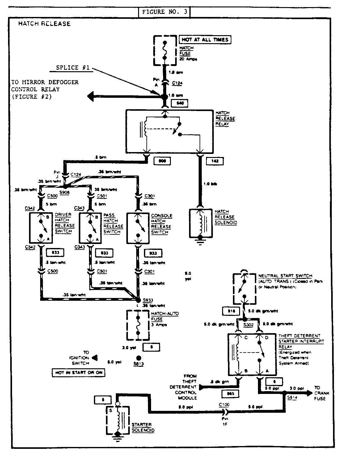
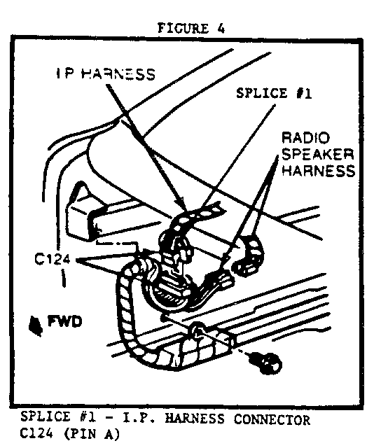
4. Solder Splice No. 1 - locate circult 540 (Figures No. 3 and No. 4) at the I/P harness connector C124, Pin A. Remove approximately 15mm (.62 in.) of insulation from the (16 ga.) orange circult 540 supply wire. Strip and wrap the mirror relay harness (14 ga.) orange wire (relay terminal E) around the stripped (16 ga.) orange circuit 540 wire and solder to complete the splice. Tape splice to insure proper electrical insulation.
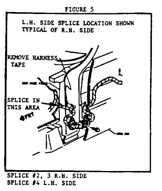
5. Soler Splice No. 2 and No. 3 - locate circuit 192 (Figures No. 2 and No. 5) under the R.H. side of the dash. It will be necessary to remove the production harness tape to locate the (16 ga.) purple wire to the R.H. mirror glass heater. Cut and strip both ends of this wire. Solder splice the (18 ga.) purple wire from Pin C of the morror relay harness into the 192 circuit wire end coming from the I/P harness (see Figure No. 2, Splice No. 2). Solder splice the 191 mm (7.5 in) long (18 ga.)light blue relay harness wire (Relay Pin A) to the remaining circuit 192 stripped wire end leading ot the R.H. mirror glass heater (see Figure No. 2, Splice No. 3). Separate and tape splices to insure proper electrical insulation. Gather and retape R.H. door harness wires.
6. Using approximatley 3 ft. (91.5 cm) of mechanics wire as a 'feeder', run the wire from the left side of the vehicle to the right behind the centre console heater controls and adjacent to the ALDL output connector. Tape the 54 in. (137 cm) long (18 ga.) light blue mirror relay harness wire (Pin A) to the feeder wire and pull through to the L.H. side of the passenger compartment.
7. Locate circuit 192 under the L.H. side of the I/P (see Figures No. 2 and No. 5). Removal of the production harness tape will be required to expose the (16 ga.) purple circuit 192 wire. Cut and tape back the (16 ga.) purple circuit 192 wire leading from the I/P harness.
NOTICE: There are two (16 ga.) purple wires in the harness at this location, one is the 92 circuit to the wiper switch, the other is the 192 circuit to the L.H. mirror. Connect the battery, turn 'on' the rear defogger switch and probe wires with a test light to identify the 192 circuit wire. Disconnect the battery before cutting the wire. Tape the cut end of the wire before taping back to avoid electrical shorts.
8. Splice No. 4 - solder splice the (18 ga.) light blue mirror relay harness wire (Relay Pin A) to the (16 ga.) purple circuit 192 wire leading to the L.H. mirror glass heater. Insulate the splice with electrical tape. Gather and retape the L.H. door harness wires.
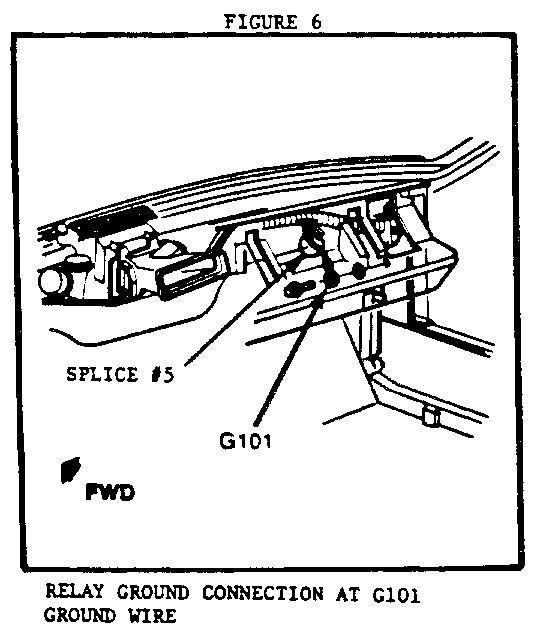
9. Splice No. 5 - locate the (12 ga.) black circuit 150 ground wire under the R.H. side of the dash (see Figures No. 2 and No. 6). Remove approximately 15 mm (.62 in.) of insulation from this wire. Strip and wrap the (18 ga.) black (Relay Pin B) mirror relay harness wire around the circuit 150 ground wire and solder. Tape splice to insulate.
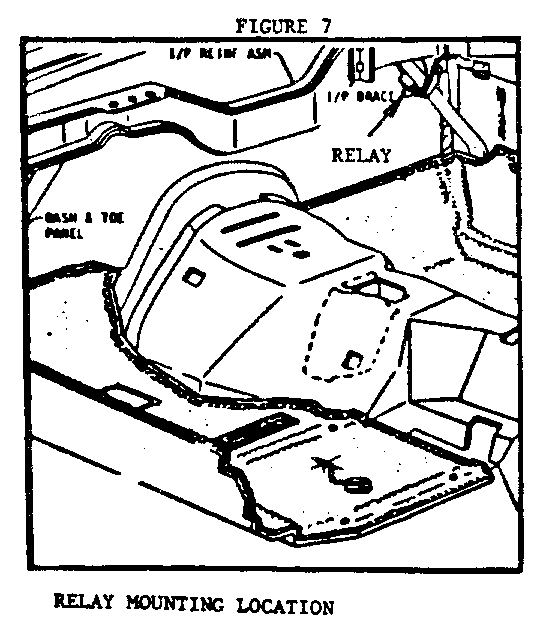
10. With the relay jumper harness plugged into the relay, mount the relay on the R.H. I/P pencil brace (see Figure 7) using a cable tie through the existing relay attaching holes and around the I/P brace. Orient the relay so that it does not contact any adjacent components that may cause a rattle. Once proper orientation is estabished, duct tape the relay to the I/P brace to prevent it from rotating.
11. Install hush panels and connect the battery.
12. Turn on the ignition key and activate the rear window defogger switch. Touch the side door mirror glass and hatch glass to verify heater operation.
Owner manuals and vehicles built prior to serial number 44571 are as shown above. Subsequent vehicles are equipped with two 20 AMP fuses, but the fuse panels have neither identifying fuse ratings nor circuit names printed on the body under the fuse cavities.
General Motors bulletins are intended for use by professional technicians, not a "do-it-yourselfer". They are written to inform those technicians of conditions that may occur on some vehicles, or to provide information that could assist in the proper service of a vehicle. Properly trained technicians have the equipment, tools, safety instructions and know-how to do a job properly and safely. If a condition is described, do not assume that the bulletin applies to your vehicle, or that your vehicle will have that condition. See a General Motors dealer servicing your brand of General Motors vehicle for information on whether your vehicle may benefit from the information.
