OVERDRIVE SWITCH IN SHIFT KNOB R&R PROCEDURE UPDATE

Model and Year: 1985 CORVETTE SHOP MANUAL (ST 364-85) UPDATE
TO: ALL CHEVROLET DEALERS
Some 1985 Corvettes, with a manual transmission, were built with the overdrive switch located in the shifter knob. The attached procedure should be used when repairing or replacing this switch.
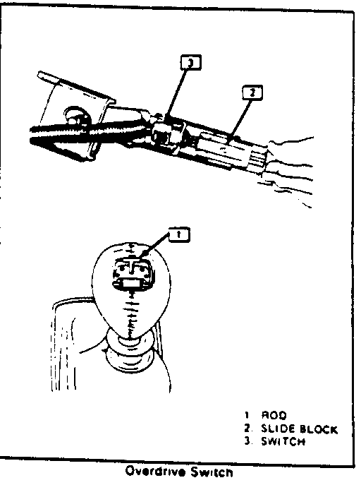
Overdrive Switch
REMOVAL
1. Disconnect negative cable at battery.
2. Remove the screws retaining trim plate for the instrument cluster. Remove the knob for the headlamp switch, lever for tilt steering column and then the trim plate.
3. Remove the screws retaining I.P. accessory trim plate and then remove the trim plate.
4. Remove the screws retaining console trim plate. Pull trim plate back and disconnect electrical lead for cigarette lighter. Remove screws retaining shift boot to trim plate, then remove trim plate.
5. Remove the overdrive switch button from the shifter knob. Use care when prying button from the knob to prevent damaging the knob or button.
6. Remove the rod for the overdrive switch from the shifter. Count the number of turns required to remove the rod.
7. Loosen the nut retaining the switch to the shifter and remove the switch and actuator block from the shifter. Care must be taken to prevent the loss of the return spring located in the actuator block.
8. Disconnect the electrical lead for the switch.
9. Remove the pin retaining the switch to the actuator block.
INSTALLATION
1. Position the switch to the actuator block and install retaining pin. Lubricate the sliding surface on the actuator block with grease.
2. Compress the return spring in the actuator block using a small screwdriver, then position the switch and block on the shifter.
3. Tighten the switch retaining nut. Apply loctite #1052624 or equivalent on the threads before tightening.
4. Install the overdrive switch rod in the shifter. Screw the rod into the actuator block the same amount of turns it took to remove. Install the switch button. The button should be flushed with the top of the shift knob. If it is not, remove the button and turn the rod in or out to make it flush.
5. Connect electrical lead for the switch.
6. Position the console trim plate to the shifter boot and install retaining screws.
7. Connect the electrical lead for the cigarette lighter.
8. Position the console trim plate and install the retaining screws.
9. Position the I.P. accessory trim plate and install the retaining screws.
10. Position the instrument cluster trim plate and install the retaining screws. Install the knob for the headlamp switch and the lever for the tilt steering column.
11. Connect negative cable at battery.

General Motors bulletins are intended for use by professional technicians, not a "do-it-yourselfer". They are written to inform those technicians of conditions that may occur on some vehicles, or to provide information that could assist in the proper service of a vehicle. Properly trained technicians have the equipment, tools, safety instructions and know-how to do a job properly and safely. If a condition is described, do not assume that the bulletin applies to your vehicle, or that your vehicle will have that condition. See a General Motors dealer servicing your brand of General Motors vehicle for information on whether your vehicle may benefit from the information.
