UPPER QUARTER PANEL CRACKS INSTALLATION PROCEDURE

Model and Year: 1984-85 CORVETTE
This bulletin is being issued to announce the release of two new service parts for repair of cracked upper quarter panels.
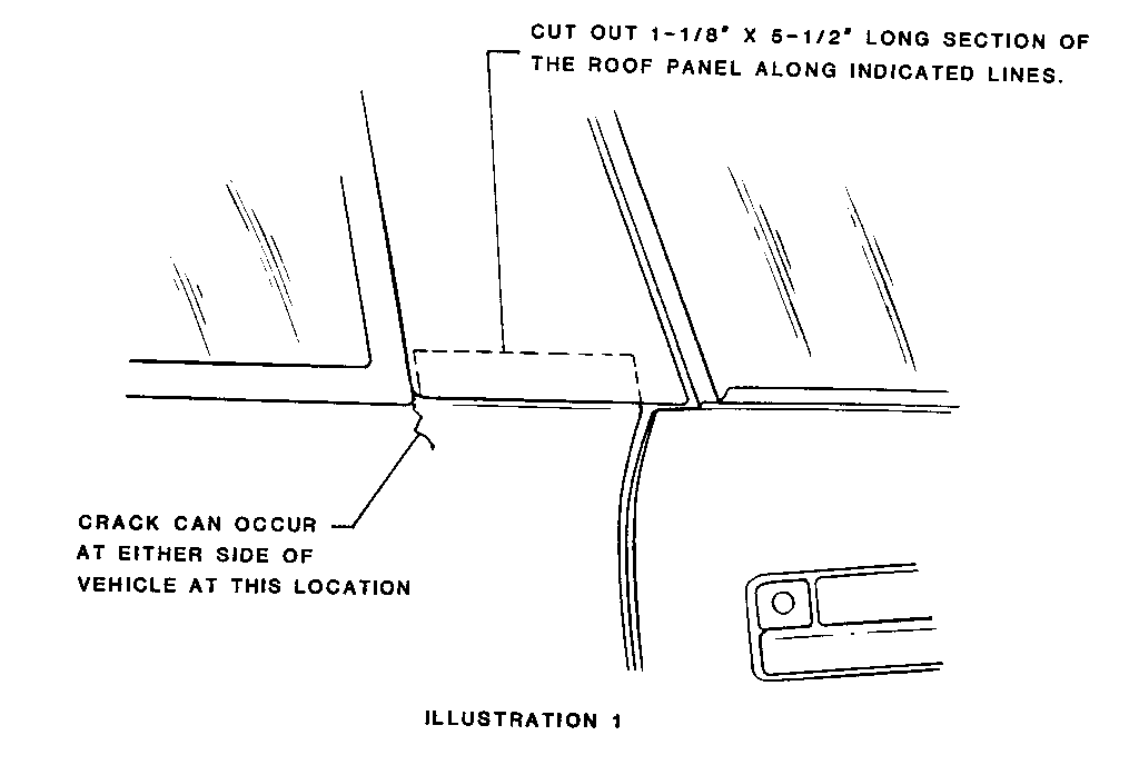
If a vehicle develops a crack in the rear upper panel (See Illustration 1) both the left and right side brackets should be installed and the cracked upper body lower panel should be replaced.
PARTS INFORMATION
PART NAME PART NUMBER --------- ----------- Rear Upper Body Lower Panel (Left) 10070219 Rear Upper Body Lower Panel (Right) 10070220
Bracket Lock Pillar to Underbody (Left) 14091061 Bracket Lock Pillar to Underbody (Right) 14091062
MATERIAL INFORMATION
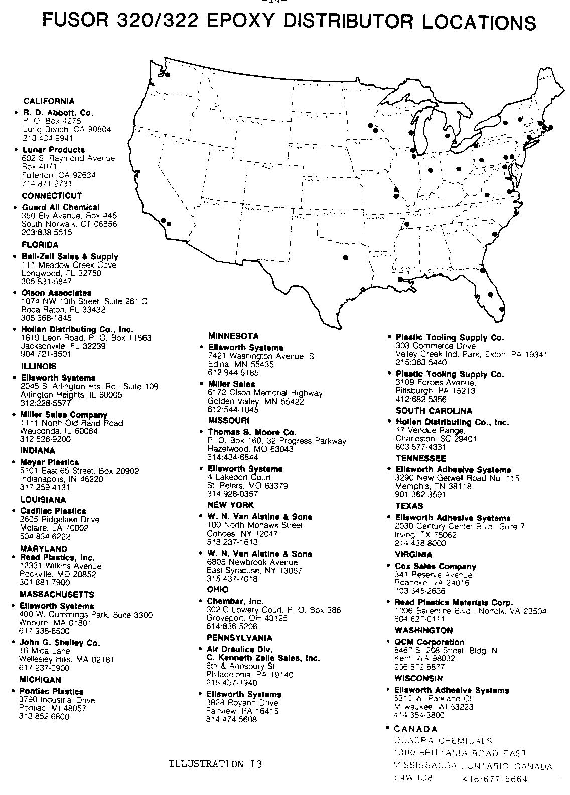
Fusor 320/322 Epoxy --- See Illustration 13
SERVICE PROCEDURE
1. Disconnect negative (-) battery cable.
2. Remove rear tire/wheel assemblies.
3. Remove rear wheelhouse inner panels.
4. Remove rear facia. Refer to Corvette Service Manual, Section 2B-4.
5. Disconnect power antenna at rear upper panel. (Left side panel replacement only).
6. Using cut-off wheel or die grinder cut a section of the rear roof panel away to gain access. (See Illustration 1).
7. Remove rear roof section by applying heat from heat gun and prying loose. Save this section for reinstallation.
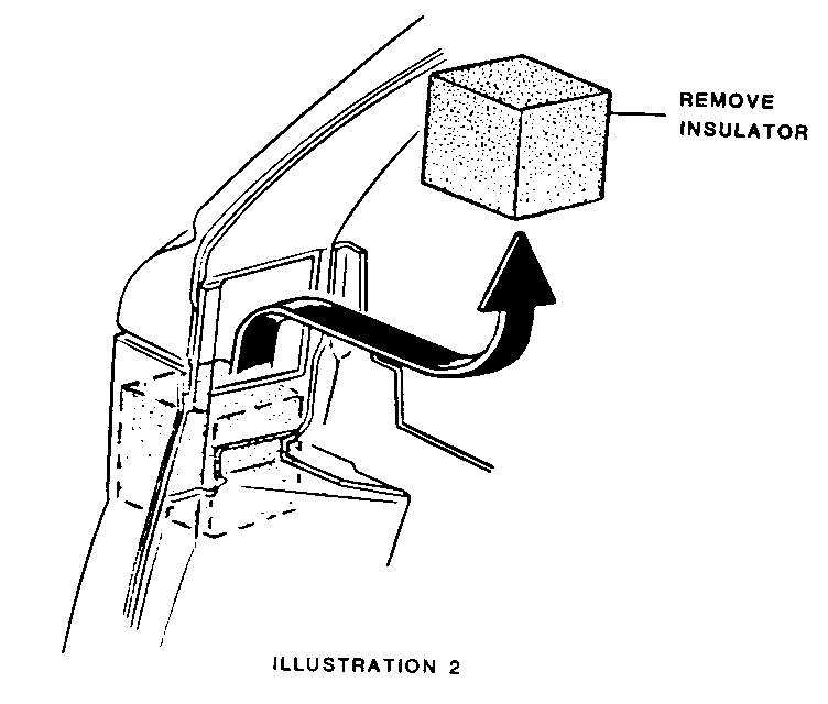
8. Remove screws from sill plate at lock pillar and loosen load floor carpet to gain access to lock pillar access hole and insulator. (See Illustration 2).
9. Remove insulator, P/N 14065008, and any other flammable material from the inside of the lock pillar.
10. Open rear hatch and remove weatherstrip trim molding and weatherstrip from area of panel(s) to be replaced.
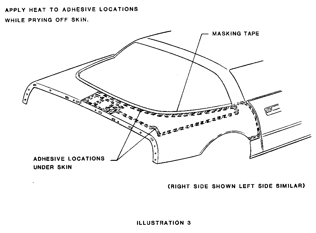
11. For either side replacement, remove complete outer skin by using heat gun and pressure, lifting skin away from inner structure. (See Illustration 3 for bond locations).
12. Remove all remaining adhesive by using heat gun and putty knife.
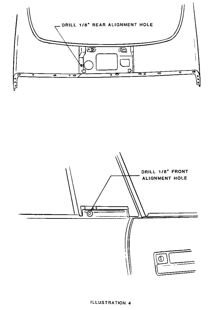
13. Fit and check alignment of new upper rear quarter panel, then drill two 1/8" diameter guide holes for sheet metal screws. (See Illustration 4). Remove screws and panel.
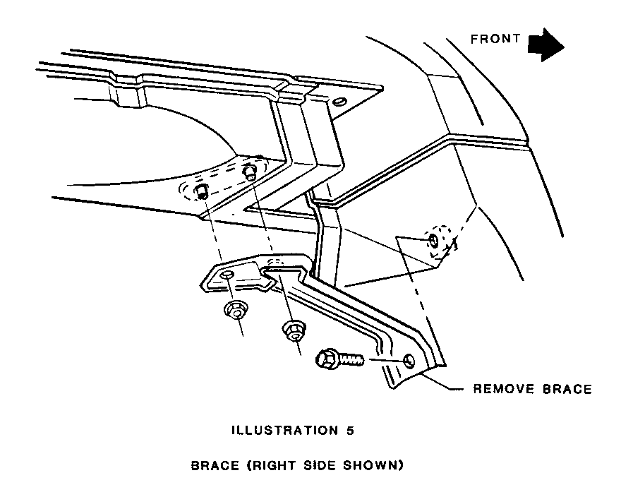
14. Remove underbody braces and discard (See Illustration 5).
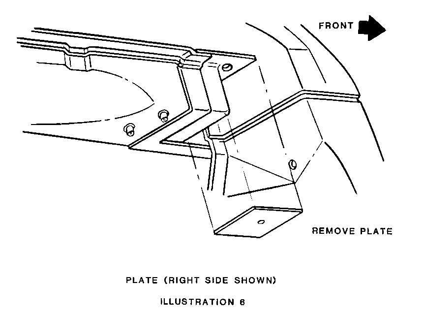
15. Remove underbody plates and discard (See Illustration 6).
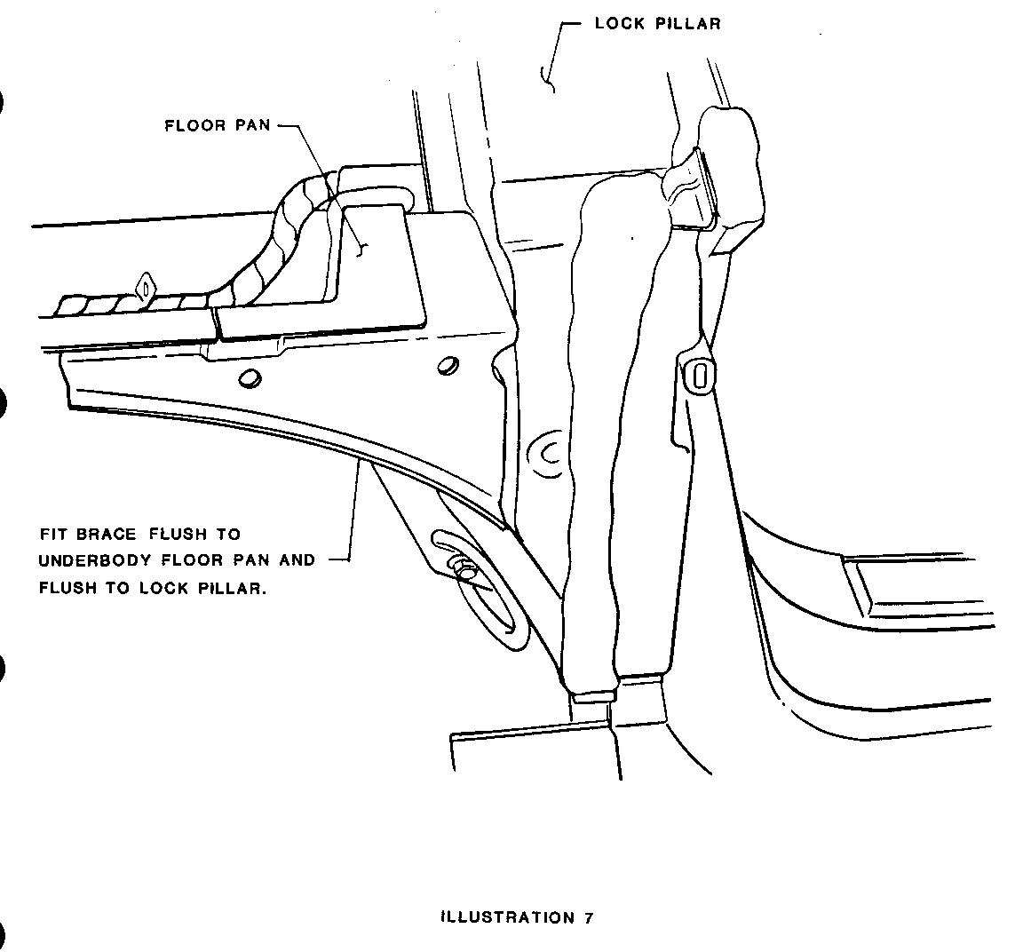
16. Remove all excess bonding agent from the underside of the rear floor so that the brackets, P/N 14091061-2, fit flush on the underbody. (See Illustration 7).
17. Hand fit the bracket into position. (Using grinder and hammer. Make sure that the bracket lays flush against both the frame and underbody.
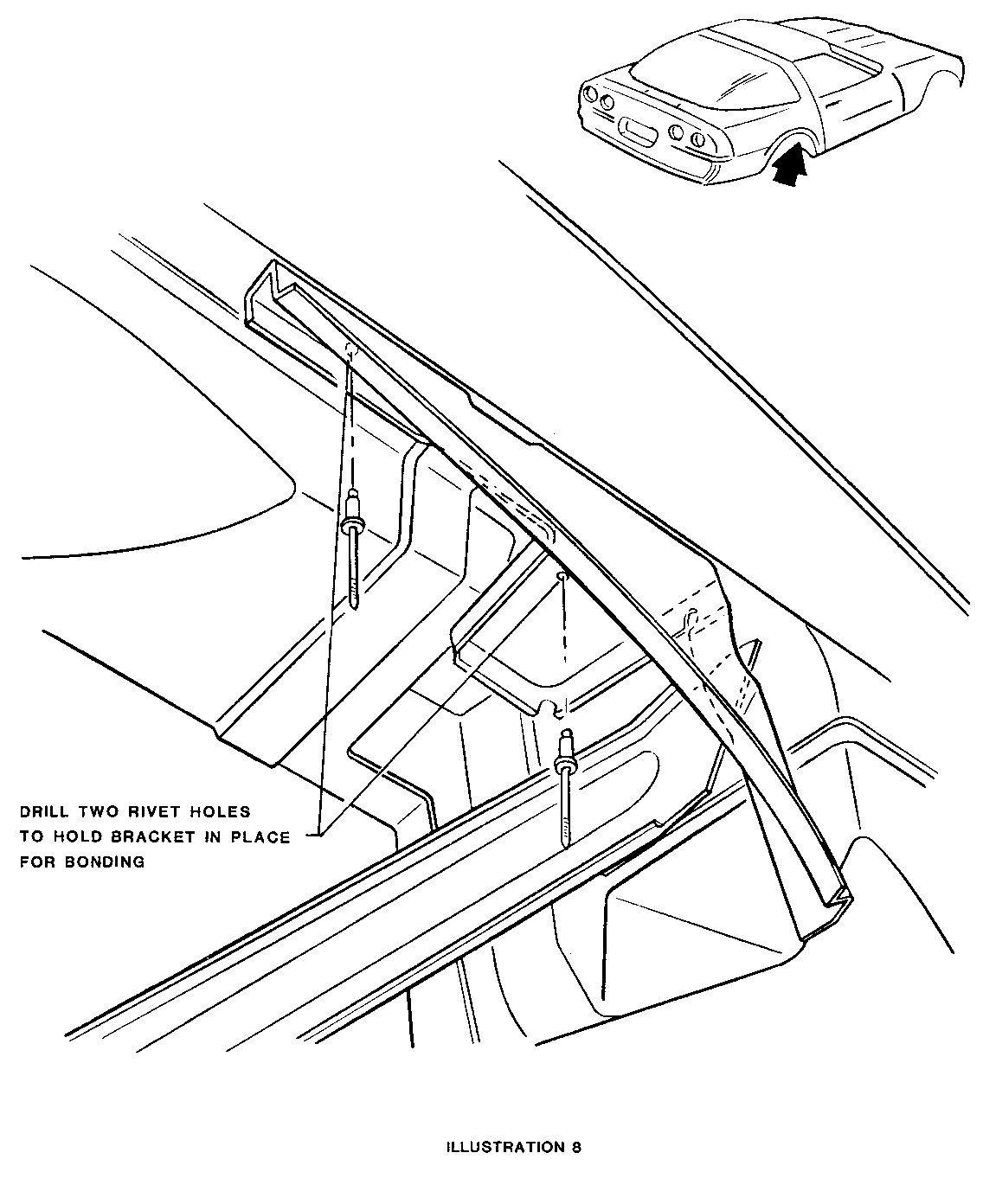
18. With bracket hand held in place drill two rivet holes. (See Illustration 8) (use 1/8 diameter long shank rivet).
19. Clean and sand the bonding surfaces of the underbody and brackets.
20. Grind the area on the frame and bracket where the bracket will be welded on.
21. Apply epoxy adhesive (Fusor 320/322) to the top of the bracket. Use recommended epoxy.
22. Locate the two pop rivets (Reg. TM) and install.
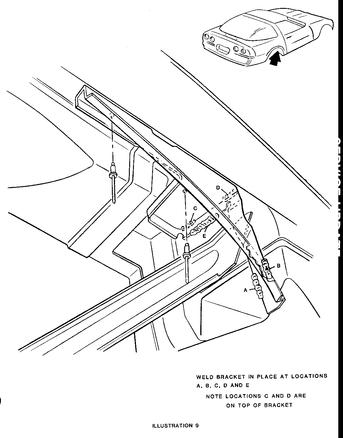
23. MIG weld (ER70s-6 wire) the bracket to the frame at each indicated locations, one weld at a time, allowing each weld to cool. (See Illustration 9).
24. Clean, prime and paint the brackets.
25. Scuff the area on the new panels to be bonded. Then clean with wax and grease remover solvent.
26. Mix epoxy until uniform color with no streaks (use 1/2 pint of Fusor 320 part A and 1/2 pint of Fusor 322 part B per side). See attachment for ordering epoxy.
27. Use plastic bag for application of epoxy. (Large zip-lock (Reg.TM) bag is preferred). Put epoxy into bag and cut corner off to get a 3/8" diameter bead.
28. Apply bead to bond surfaces on vehicle.
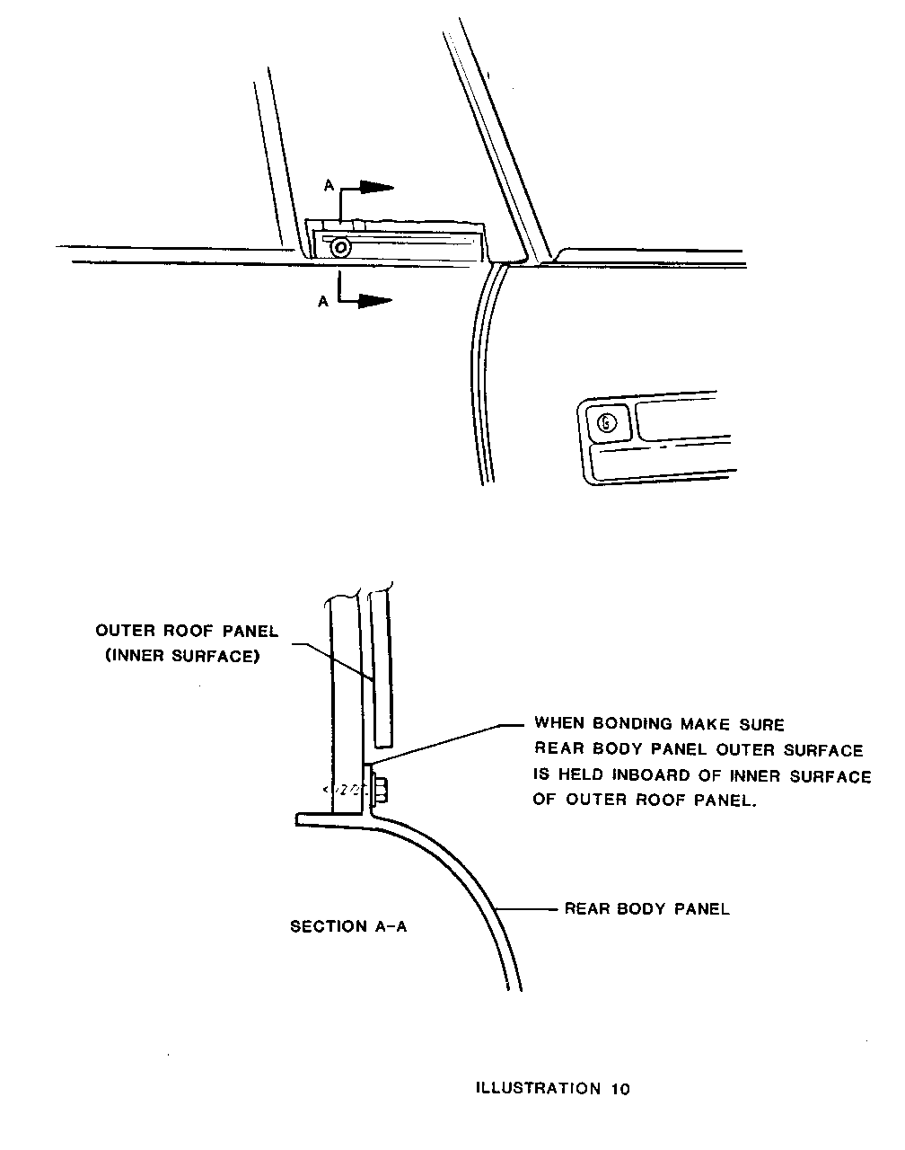
29. Install upper quarter panel and fit. Insert alignment screws and clamp loosely where necessary to fit. Be sure front top corner of rear upper quarter panel is held below inner surface of outer roof panel. (See Illustration 10).
30. Let set for thirty (30) minutes.
31. Remove clamps and screws.
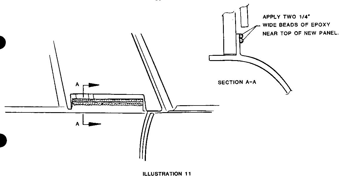
32. Use epoxy adhesive (Fusor 320/322) to set in the roof panel section removed earlier. (See Illustration 11).
33. V-groove and apply polyester filler.
34. Sand.
35. Prime and paint.
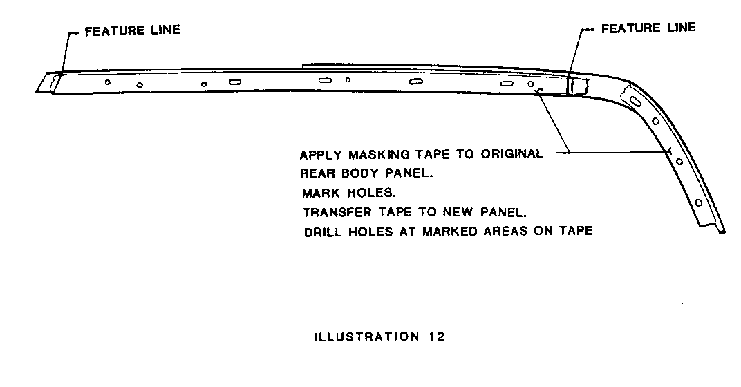
36. Mark and drill rear fascia holes (See Illustration 12).
37. Reverse tear down procedure.
LABOR OPERATION LABOR NUMBER TIME ------ ---- Inc. refinish and paint as necessary.
Install L.H. Panel, both T1178 10.8 GI brackets Add to clear coat .3 CD
Install R.H. Panel, both T1179 11.0 GI brackets Add to clear coat .3 CD
Install panels on both side, T1180 14.9 GI both brackets Add to clear coat .6 CD
General Motors bulletins are intended for use by professional technicians, not a "do-it-yourselfer". They are written to inform those technicians of conditions that may occur on some vehicles, or to provide information that could assist in the proper service of a vehicle. Properly trained technicians have the equipment, tools, safety instructions and know-how to do a job properly and safely. If a condition is described, do not assume that the bulletin applies to your vehicle, or that your vehicle will have that condition. See a General Motors dealer servicing your brand of General Motors vehicle for information on whether your vehicle may benefit from the information.
