SERVICE MANUAL UPDATE ENGINE FUEL

Subject: REVISED SECTION 6C "ENGINE FUEL"
Model and Year: 1989 Y CAR
TO: ALL CHEVROLET DEALERS
Information for the 1989 5.7L L98 (VIN 8) "Y" car, Section 6C "Engine Fuel" of the Service Manual has been revised. Replace the old section with the attached new section.
SECTION 6C ENGINE FUEL 5.7L (VIN 8) CONTENTS ------------------------ GENERAL DESCRIPTION ............ 6C-1 FUEL TANK ................... 6C-1 Fuel Tank Filler Neck ........... 6C-1 Fuel Filler Cap ............... 6C-2 FUEL LEVEL METER (SENDER UNIT) ASSEMBLY ................. 6C-2 Fuel Level Meter .............. 6C-2 Fuel Pump ................. 6C-2 Fuel Pump Filter (Strainer/Sock) .... 6C-2 Pulsator ................... 6C-3 IN-LINE FUEL FILTER ........... 6C-3 FUEL/ VAPOR PIPES and HOSES ...... 6C-3 Fuel Line 0-rings ............. 6C-3 ACCELERATOR CONTROLS ......... 6C-3 DIAGNOSIS .................... 6C-3 ALCOHOL-IN-FUEL .............. 6C-3 Testing Procedure ............. 6C-3 FUELTANK LEAK CHECK .......... 6C-3 On-vehicle ................. 6C-3 Off-vehicle ................. 6C-4 FUEL SYSTEM PRESSURE TEST See Section 6E3, Chart A-7 FUEL LEVEL METER (SENDER UNIT) DIAGNOSIS See Section 8A FUEL PUMP ELECTRICAL DIAGNOSIS See Section 6E3 and 8A ON-VEHICLE SERVICE ............ 6C-4 FUEL SYSTEM PRESSURE RELIEF ..... 6C-4 IN-LINE FUEL FILTER REPLACEMENT ... 6C-4 DRAINING FUEL TANK ............ 6C-5 FUEL LEVEL METER ASSEMBLY REPLACEMENT .............. 6C-5 Fuel Pump Filter Replacement ..... 6C-6 Fuel Pump Replacement ........ 6C-7 Pulsator Replacement .......... 6C-7 Fuel Level Meter Replacement ..... 6C-8 FUEL TANK REPLACEMENT ....... 6C-8 FUEL SYSTEM CLEANING .......... 6C-11 FUEL FEED AND RETURN PIPE/HOSE ASSEMBLIES REPLACEMENT ..... 6C-13 FUEL VAPOR PIPES AND HOSES REPAIR/ REPLACEMENT .............. 6C-14 ACCELERATOR CONTROL CABLE ..... 6C-15 ACCELERATOR PEDAL ............ 6C-16 TORQUE SPECIFICATIONS ........ 6C-16
All new General Motors vehicles are certified by the United States Environmental Protection Agency as conforming to the requirements of the regulations for the control of air pollution from new motor vehicles. This certification is contingent on certain adjustments being set to factory standards. In most cases, these adjustment points either have been permanently sealed and/or made inaccessible to prevent indiscriminate or routine adjustment in the field. For this reason, the factory procedure for temporarily removing plugs, caps, etc., for purposes of servicing the product must be strictly followed, and wherever practicable, returned to the original intent of the design.
GENERAL DESCRIPTION
The fuel supply is stored in the fuel tank. An electric fuel pump, attached to the fuel level meter assembly (inside the fuel tank) pumps fuel through an in-line filter to the fuel rail assembly. The pump is designed to provide fuel at a pressure above the regulated pressure needed by the injectors. A pressure regulator, an integral part of the fuel rail assembly, keeps fuel available to the injectors at a regulated pressure. Unused fuel is returned to the fuel tank by a separate line. For further information on the fuel injection system, refer to "Fuel Metering System" located in DRIVEABILITY AND EMISSIONS (SECTION 6E3-C2).
Unleaded fuel must be used with all gasoline engines for proper emission control system operation. Using unleaded fuel will also decrease spark plug fouling and extend engine oil life. Leaded fuel can damage the emission control system, and its use can result in loss of emission warranty coverage.
All cars with gasoline engines are equipped with an Evaporative Emission System that minimizes the escape of fuel vapors to the atmosphere. Information on this system is found in DRIVEABILITY AND EMISSIONS (SECTION 6E3-C3).
FUEL TANK
The fuel tank is used to store fuel for the vehicle. The tank is located in the rear of the vehicle and held in place by two metal straps that are attached to the frame. The fuel tank consists of a tough pliable polyethylene liner inside a steel container.
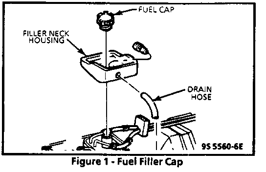
Fuel Tank Filler Neck (Figure 1)
To prevent refueling with leaded fuel, the fuel filler neck on gasoline engine cars has a built-in restrictor and deflector.
Fuel Filler Cap (Figure 1)
The fuel tank filler neck is equipped with a threaded-type cap. The threaded part of the cap requires several turns counter clockwise to remove. A built-in torque-limiting device prevents over tightening. To install, turn the cap clockwise until a clicking noise is heard. This signals that the correct torque has been reached and the cap is fully seated.
NOTICE: If a fuel filler cap requires replacement, use only a cap with the same features. Failure to use the correct cap can result in a serious malfunction of the system.
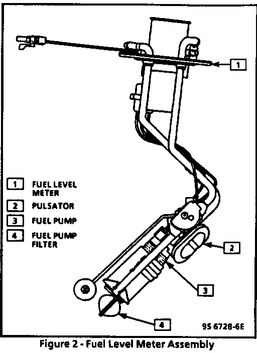
FUEL LEVEL METER (SENDER UNIT) ASSEMBLY (Figure 2)
The fuel level meter (sender unit) assembly is located inside the fuel tank and is attached to the top of the fuel tank.
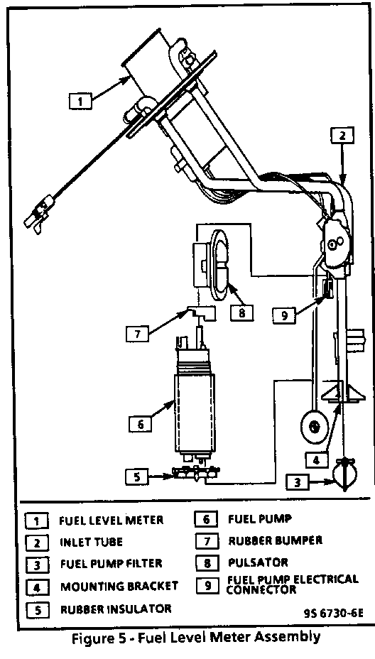
The fuel level meter assembly consists of the following major components: a fuel level meter, fuel pump, fuel pump filter, pulsator and the roll-over valve.
Fuel Level Meter (Figure 2)
The fuel level meter consists of the fuel tank filler neck, a float, wire float arm, sensor and the roll-over valve. Fuel is sensed by the position of the float arm, and a signal is sent to the display in the vehicle instrument cluster.
The roll-over valve is pressed into the vent tube of the fuel level meter and is not serviced separately. The roll-over valve prevents fuel from entering the engine compartment if the vehicle rolls over by shutting off the vent line to the charcoal canister.
Fuel Pump (Figure 2)
The fuel pump is an electric high pressure roller vain pump which is mounted to the fuel level meter assembly inside the fuel tank. The fuel is pumped to the engine at a specified flow and pressure via the fuel pump. Excess fuel is returned to the fuel tank via the return line. The fuel pump delivers a constant flow of fuel to the engine even during low fuel conditions and aggressive vehicle maneuvers.
The electric fuel pump operation is controlled by the ECM through a fuel pump relay. Refer to DRIVEABILITY AND EMISSIONS (SECTION 6E3- C2) and ELECTRICAL DIAGNOSIS (SECTION 8A) of this manual for further description and a wiring diagram of fuel pump relay.
Fuel Pump Filter (Strainer/Sock) (Figure 2) ------------------------------------------- A woven plastic fuel pump filter (strainer/sock) is attached to the lower end of the fuel pump in the fuel tank. The functions of the fuel pump filter are to filter contaminants and to wick fuel.
The life of the fuel pump filter is generally considered to be that of the fuel pump. The fuel pump filter is self-cleaning and normally requires no maintenance. Fuel stoppage at this point indicates that the fuel tank contains an abnormal amount of sediment or water. In which case the tank should be thoroughly cleaned. (See "Fuel System Cleaning".) If the fuel pump filter is plugged, replace it with a new fuel pump filter.
Pulsator (Figure 2)
The pulsator is installed between the fuel pump and the fuel level meter to dampen fuel pulsation and reduce noise generated by the fuel pump.
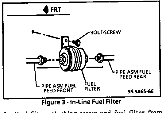
IN-LINE FUEL FILTER
A fifteen micron in-line fuel filter is located in the fuel feed line and attached to the right frame rail, at the front of the vehicle. The in-line fuel filter is protected by a shield. This shield protects the fuel filter against exhaust heat and road hazards.
FUEL/VAPOR PIPES AND HOSES -------------------------- The fuel feed and return line assemblies extend from the fuel level meter assembly to the fuel rail assembly. The fuel line assemblies are made of steel pipe and fuel resistant rubber hose and secured to the underbody.
The vapor line extends from the fuel level meter assembly to the charcoal canister. It is made up of sections of fuel resistant rubber hoses.
Fuel Line 0-rings
The feed and return line connections are sealed with 0-ring seals. Fuel system 0-ring seals are made of special material, and should only be serviced with the correct service part.
ACCELERATOR CONTROLS
The accelerator control system is cable type. There are no linkage adjustments. Therefore, the specific cable for each application must be used.
DIAGNOSIS
ALCOHOL-IN-FUEL
Alcohol-in-fuel can be detrimental to fuel system components and may cause driveability problems such as hesitation, lack of power, stall, no start, etc.
The problems may be due to fuel system corrosion and subsequent fuel filter plugging, deterioration of rubber components and/or air-fuel mixture leaning.
Various types and concentrations of alcohols are used in commercial fuel. Some alcohols are more detrimental to fuel system components than others. If an excessive amount of alcohol in the fuel is suspected as the cause of a driveability condition, the following procedure may be used to detect the presence of alcohol in the fuel. In this procedure, water is used to extract the alcohol from the fuel.
Testing Procedure
The fuel sample should be drawn from the bottom of the tank so that any water present in the tank will be detected. The sample should be bright and clear. If the sample appears cloudy, or contaminated with water (as indicated by a water layer at the bottom of the sample), this procedure should not be used, and the fuel system should be cleaned (see "Fuel System Cleaning").
1. Using a 100 ml cylinder with 1 ml graduation marks, fill with fuel to the 90 ml mark.
2. Add 10 ml of water to bring the total fluid volume to 100 ml and install a stopper.
3. Shake vigorously for 10 to 15 seconds.
4. Carefully loosen the stopper to release pressure.
5. Close the stopper and shake vigorously again for 10 to 15 seconds.
6. Put the graduated cylinder on a level surface for approximately 5 minutes to allow adequate liquid separation.
If alcohol is present in the fuel, the volume of the lower layer (which would now contain both alcohol and water) will be greater than 10 ml. For example, if the volume of the lower layer is increased to 15 ml, it will indicate at least 5 percent alcohol in fuel. The actual amount of alcohol may be somewhat greater because this procedure does not extract all of the alcohol from the fuel.
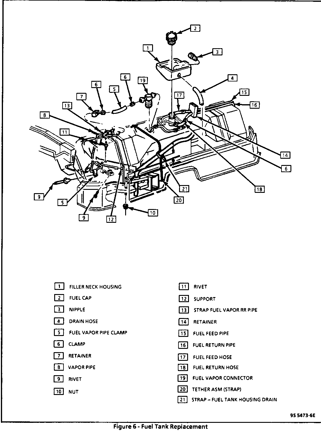
FUEL TANK LEAK CHECK (Figure 6)
Important
o Before removing the fuel tank for a suspected leak, make sure fuel hoses are not leaking onto the tank. Also, make sure fuel is not leaking around fuel level meter assembly gasket.
On-Vehicle
A visual inspection of the tank, and a leak-check of the fuel tank bladder are the only checks possible on-vehicle. If fuel is leaking from the tank, replace tank and check for leaks.
1 . Place a dry chemical (Class B) fire extinguisher near the work area.
2. Relieve fuel system pressure (see "Fuel System Pressure Relief ").
3. Drain fuel tank (see "Draining Fuel Tank").
4. Disconnect fuel feed hose, and cap tube on fuel level meter assembly.
5. Disconnect the the vapor vent hose between the fuel level meter assembly and the fuel tank "TEE" fitting at the "TEE."
6. Plug hose and cap open end of "TEE" fitting.
7. Disconnect vapor vent hose to canister from other side of "TEE" fitting.
8. Connect a piece of hose to the open end of "TEE" fitting, and place other end into a container of water.
9. Install fuel filler cap.
10. Apply 7 to 10 kPa (1 to 11/2 psi) air pressure to the fuel return tube on the fuel level meter assembly.
- Air bubbles appearing in container indicate a leak in the bladder.
11. Replace fuel tank if bladder is leaking (see "Fuel Tank Replacement").
Off-Vehicle
Important
o "Off-Vehicle" leak check requires two sources of regulated air pressure.
o This check requires a fuel level meter assembly and fuel filler cap to be installed in the fuel tank.
1. Cap fuel feed tube and vapor vent tube on fuel level meter assembly.
2. Cap one end of fuel tank "TEE" fitting.
3. Connect a piece of hose to the open end of "TEE" fitting, and place other end into a container of water.
4. Tighten fuel filler cap.
5. Apply 7 to 10 kPa (1 to 11/2 psi) air pressure to the fuel return tube on the fuel level meter assembly.
- Air bubbles appearing in container indicate a leak in the bladder. Replace fuel tank if bladder is leaking (see "Fuel Tank Replacement").
- If no bubbles appear, continue with cheek.
NOTICE: Equal air pressure must applied to the fuel return tube on the fuel level meter assembly before air pressure is applied to the vent "TEE" opening, or damage to bladder may result.
6. Release air supply, and submerge tank in water or apply soap solution to outside of tank.
7. Reapply 7 to 10 kPa (1 to 11/2 psi) air pressure to the fuel return tube on the fuel level meter assembly. With a second air source, apply 7 to 10 kPa (1 to 11/2 psi) air pressure to the hose connected to the "TEE" fitting.
- Air bubbles indicate a leak in the metal tank. Replace fuel tank if it is leaking (see "Fuel Tank Replacement").
NOTICE: Air pressure must be released from the hose connected to the "TEE" fitting before releasing pressure from the fuel return tube on the fuel level meter assembly, or damage to bladder may result.
8. Release air pressure from hose connected to "TEE" fitting.
9. Release air pressure from fuel return tube on the fuel level meter assembly.
ON-VEHICLE SERVICE
Important
o Before attempting any "On-Vehicle Service" place a dry chemical (Class B) fire extinguisher near work area.
FUEL SYSTEM PRESSURE RELIEF
Tool required: J 34730-1 Fuel Pressure Gage
CAUTION:
o To reduce the risk of fire and personal injury, it is necessary to relieve the fuel system pressure before servicing fuel system components.
o A small amount of fuel may be released when servicing fuel lines or connections. In order to reduce the chance of personal injury, cover fuel line fittings with a shop towel before disconnecting, to catch any fuel that may leak out. Place the towel in an approved container when disconnect is completed.
1. Disconnect negative battery terminal to avoid possible fuel discharge if an accidental attempt is made to start the engine.
2. Loosen fuel riller cap to relieve tank pressure.
3. Connect J 34730-1 to fuel pressure valve. Wrap a shop towel around fitting while connecting gage to avoid spillage.
4. Install bleed hose into an approved container and open valve to bleed system pressure. Fuel connections are now safe for servicing.
5. Drain any fuel remaining in gage into an approved container.
IN-LINE FUEL FILTER REPLACEMENT (Figure 3)
Remove or Disconnect
1. Negative battery terminal.
2. Relieve fuel system pressure (see "Fuel System Pressure Relief").
3. Raise vehicle on hoist.
4. Fuel filter shield attaching screws (2) and fuel filter shield (not shown).
5. Fuel lines from filter.
6. Fuel filter attaching screw and fuel filter from vehicle.
Inspect
o Fuel line 0-rings for cuts, nicks, swelling or distortion. Replace if necessary.
Install or Connect
1. Loosely install new filter with filter attaching screw.
2. Fuel lines to the fuel filter.
Tighten
o Use back-up wrench to prevent filter from turning.
o Fuel line fittings to 30 N-m (22 lb. ft.).
3. Secure fuel filter attaching screw.
4. Fuel filter shield and attaching screws (2) (not shown).
5. Lower vehicle.
6. Fuel filler cap.
7. Negative battery terminal.
Inspect
o Turn ignition switch to "ON," position for two seconds, then turn to "OFF" for five seconds. Again turn to"ON" position, and check for fuel leaks.
DRAINING FUEL TANK
CAUTION:
Never drain or store fuel in an open container due to the possibility of fire or explosion.
1. Use a hand operated pump device to drain as much fuel through the filler tube as possible.
2. If a hand operated pump device cannot be used to complete the draining process:
A. Disconnect negative battery terminal.
B. Relieve fuel system pressure (see "Fuel System Pressure Relief").
C. Connect a siphon to the return (not main) fuel pipe at the fuel level meter assembly. Siphon remaining fuel.
D. Reinstall any removed hoses, lines and cap.
E. Reconnect negative battery terminal.
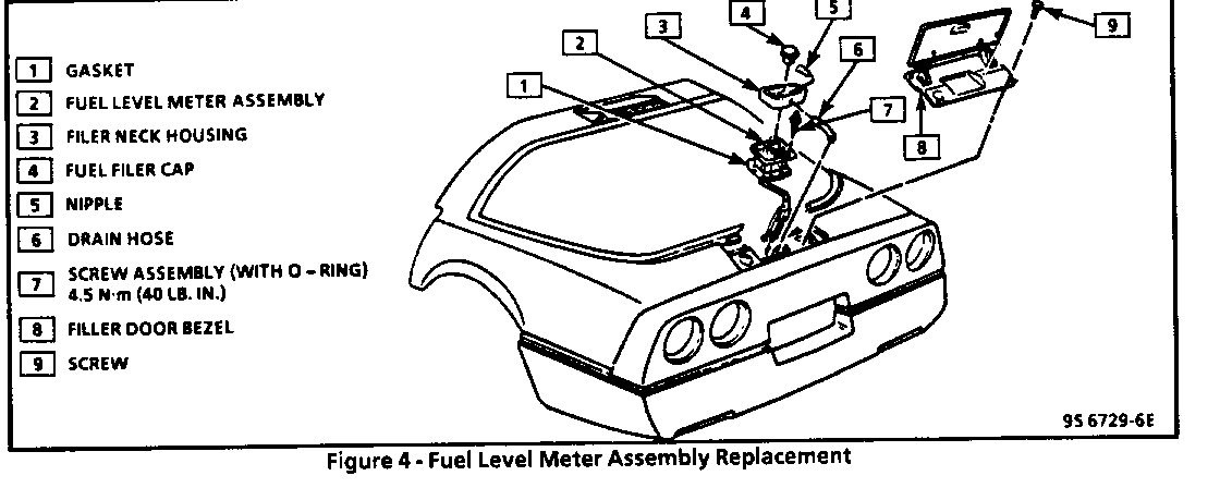
FUEL LEVEL METER ASSEMBLY REPLACEMENT (Figure 4)
CAUTION:
To reduce the risk of fire and personal injury that may result from a fuel leak, always replace fuel level meter gasket when reinstalling fuel level meter assembly.
Remove or Disconnect
1. Negative battery terminal.
2. Relieve fuel system pressure (see "Fuel System Pressure Relief').
3. Drain fuel tank (see "Draining Fuel Tank").
4. Filler door bezel attaching screws (4) and bezel.
5. Fuel filler cap.
6. Lift fuel tank filler neck housing and disconnect drain hose from nipple.
7. Fuel tank filler neck housing.
8. Fuel lines and fuel vapor lines.
9. Fuel level meter electrical connector.
10. Fuel level meter assembly attaching screws (9), fuel level meter assembly and gasket. Discard gasket.
Clean
o Gasket sealing surfaces.
Inspect
o Attaching screw 0-rings for cuts, nicks, swelling or distortion. Replace if necessary.
o Fuel lines and vent lines for cuts, nicks, swelling or distortion. Replace if necessary.
Install or Connect
1. Position new gasket on fuel tank with notch facing forward in right hand corner of fuel tank.
Important
o Care should be taken not to fold over or twist the fuel pump filter when installing the fuel level meter assembly as this will restrict fuel flow. Also, assure that the fuel pump filter does not block full travel of float arm.
2. Fuel level meter assembly and attaching screws (9).
Tighten
o Fuel level meter assembly attaching screws alternately and evenly to 4.5 N-m (40 lb. in.).
3. Fuel level meter electrical connector.
4. Fuel lines and fuel vapor lines.
5. Fuel drain hose to nipple on rubber filler neck housing, and then position housing around fuel tank filler neck.
6. Fuel filler cap.
7. Filler door bezel with attaching screws (4).
8. Negative battery terminal.
Inspect
o Turn ignition switch to "ON," position for two seconds, then turn to "OFF" for five seconds. Again turn to"ON" position, and check for fuel leaks.
Fuel Pump Filter Replacement (Figures 4, 5)
Remove or Disconnect
1. Negative battery terminal.
2. Relieve fuel system pressure (see "Fuel System Pressure Relief').
3. Fuel level meter assembly (see "Fuel Level Meter Assembly Replacement").
Disassemble
1. Note position of fuel pump filter on fuel pump.
2. Support pump with one hand and grasp filter with other hand.
- Rotate filter in one direction and pull off of pump. Discard filter after inspection.
Inspect
o Fuel pump filter. If filter is contaminated, it must be replaced and the fuel tank should be removed and cleaned.
o Fuel pump inlet for dirt and debris. If found, fuel pump should be replaced.
Assemble
o New pump filter in same position as noted during disassembly. Push on outer edge of ferrule until fully seated.
Install or Connect
1. Fuel level meter assembly (see "Fuel Level Meter Assembly Replacement").
2. Negative battery terminal.
Inspect
o Turn ignition switch to "ON," position for two seconds, then turn to "OFF" for five seconds. Again turn to"ON" position, and check for fuel leaks.
Fuel Pump Replacement (Figures 4, 5)
Remove or Disconnect
1. Negative battery terminal.
2. Relieve fuel system pressure (see "Fuel System Pressure Relief").
3. Fuel level meter assembly (see "Fuel Level Meter Assembly Replacement").
Disassemble
1. Note position of fuel filter on fuel pump.
2. Support pump with one hand and grasp filter with other hand.
- Rotate filter in one direction and pull off of pump. Discard filter.
3. Fuel pump electrical connector.
4. Place fuel level meter assembly upside down on bench.
- Pull fuel pump downward to remove from mounting bracket, then tilt pump outward and remove from pulsator.
NOTICE: Do not run fuel pump unless submerged in fuel.
Inspect
o Fuel pump inlet for dirt and debris. If found, fuel pump should be replaced.
Assemble
1. Rubber bumper and rubber insulator on fuel pump.
2. Position fuel level meter assembly upside down.
- Install fuel pump between pulsator and mounting bracket.
3. Fuel pump electrical connector.
Important
o Always install a new pump filter when replacing fuel pump.
4. New pump filter in same position as noted during disassembly. Push on outer edge of ferrule until fully seated.
Install or Connect
1. Fuel level meter assembly (see "Fuel Level Meter Assembly Replacement").
2. Negative battery terminal.
Inspect
o Turn ignition switch to "ON," position for two seconds, then turn to "OFF" for five seconds. Again turn to"ON" position, and check for fuel leaks.
Pulsator Replacement (Figures 4, 5)
Remove or Disconnect
1. Negative battery terminal.
2. Relieve fuel system pressure (see "Fuel System Pressure Relief').
3. Fuel level meter assembly (see "Fuel Level Meter Assembly Replacement").
Disassemble
1. Note position of fuel filter on fuel pump.
2. Support pump with one hand and grasp filter with other hand.
- Rotate filter in one direction and pull off of pump. Discard filter.
3. Fuel pump electrical connector.
4. Place fuel level meter assembly upside down on bench.
- Pull fuel pump downward to remove from mounting bracket, then tilt pump outward and remove from pulsator.
NOTICE: Do not run fuel pump unless submerged in fuel.
5. Note position of pulsator on inlet tube, then remove pulsator from tube.
Inspect
o Dry pulsator with a shop towel.
o Shake pulsator while listening for trapped fuel movement inside pulsator.
o If fuel is heard inside pulsator, replace pulsator.
o Fuel pump inlet for dirt and debris. If found, fuel pump should be replaced.
Assemble
1. Pulsator in same position as noted during disassembly.
2. Rubber bumper and rubber insulator on fuel pump.
3. Position fuel level meter assembly upside down.
- Install fuel pump between pulsator and mounting bracket.
4. Fuel pump electrical connector.
Important
o Always install a new pump filter when replacing fuel pump.
5. New pump filter in same position as noted during disassembly. Push on outer edge of ferrule until fully seated.
Install or Connect
1. Fuel level meter assembly (see "Fuel Level Meter Assembly Replacement").
2. Negative battery terminal.
Inspect
o Turn ignition switch to "ON," position for two seconds, then turn to "OFF" for five seconds. Again turn to "ON" position, and check for fuel leaks.
Fuel Level Meter Replacement (Figures 4, 5)
Remove or Disconnect
1. Negative battery terminal.
2. Relieve fuel system pressure (see "Fuel System Pressure Relief").
3. Fuel level meter assembly (see "Fuel Level Meter Assembly Replacement").
Disassemble
o Fuel level meter assembly according to instructions for "Fuel Pump Pulsator Replacement." Transfer fuel pump and pulsator to new fuel level meter assembly.
Assemble
o Fuel level meter assembly according to instructions for "Fuel Pump Pulsator Replacement."
Install or Connect
1. Fuel level meter assembly (see "Fuel Level Meter Assembly Replacement").
2. Negative battery terminal.
Inspect
o Turn ignition switch to "ON," position for two seconds, then turn to "OFF" for five seconds. Again turn to"ON" position, and check for fuel leaks.
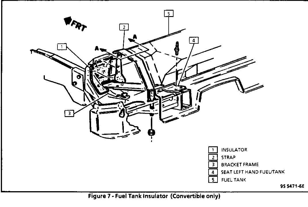
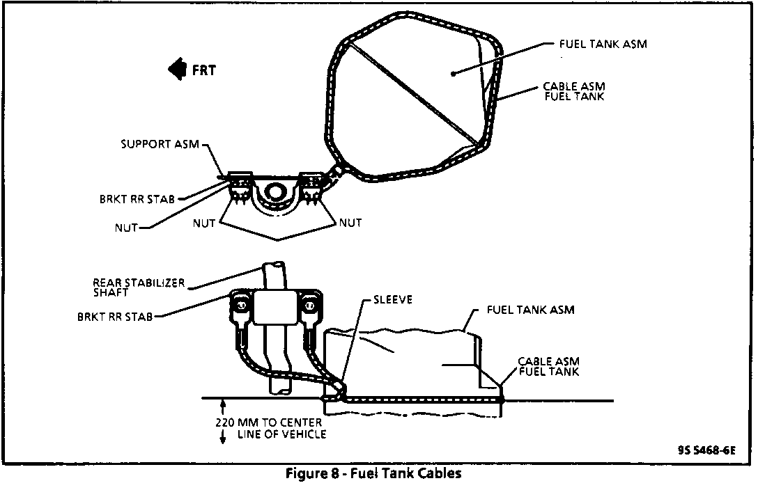
FUEL TANK REPLACEMENT (Figures 6, 7, 8)
Remove or Disconnect
CAUTION:
To help avoid personal injury when a vehicle is on a hoist, provide additional support for the vehicle on the opposite end from which components are being removed. This will reduce the possibility of the vehicle falling off the hoist.
Important
o Fuel tank replacement requires body disassembly see BODY SERVICE (SECTION 10-7).
1. Negative battery terminal.
2. Relieve fuel system pressure (see "Fuel System Pressure Relief').
3. Drain fuel tank (see "Draining Fuel Tank").
4. Filler door bezel attaching screws (4) and bezel.
5. Fuel filler cap.
6. Lift fuel tank filler neck housing and disconnect drain hose from nipple.
7. Fuel tank filler neck housing.
8. Fuel level meter assembly electrical connector.
9. Fuel feed hose, return hose, and vapor hose from fuel level meter assembly.
10. License plate to gain access for and removal of carriage bolts (2) securing fascia to impact bar.
11. Raise vehicle on hoist.
12. Spare tire and tire carrier from frame.
13. Intermediate pipe at converter.
- Hanger bolt to intermediate pipe.
- Hanger nuts from muffler assembly.
- With aid of assistant remove intermediate pipe and mufflers as an assembly.
14. Both rear inner fender braces at frame.
15. Both rear inner fender panels.
16. Antenna ground strap and clip at frame and at antenna base.
17. Fuel vapor hose from fuel vapor pipe at bottom of fuel tank.
18. Fuel tank cable attaching nuts (4) and both fuel tank cables from anti-swaybar supports.
19. Attaching screws (2) securing bottom edge of fascia to energy absorber pad.
20. All rear lamps sockets (side marker, tail backup, license plate and spare tire) from lens assemblies.
21. Attaching nuts (4) securing each side of fascia to horizontal body retainer.
22. Nuts (5) securing each side of vertical body retainer to fascia.
23. Support rear frame section with jackstands.
24. With the aid of an assistant, remove rear subframe to main frame bolts (8).
- Pull fuel tank and frame assembly to rear pushing cover outward and letting rear of frame assembly down to clear cover.
- Place fuel tank and frame assembly in a suitable work area.
25. Fuel tank rear retaining strap nuts (2), front retaining strap bolts (2) and fuel tank retaining straps (2).
26. With aid of assistant remove fuel tank.
27. If fuel tank is being replaced transfer:
- Vent hose.
- Fuel connector.
- Fuel level meter assembly (see "Fuel Level Meter Assembly Replacement").
Install or Connect
1. Reverse removal procedure.
Tighten
o Front fuel tank retaining strap bolts to 15 N-m (11 lb. ft.).
o Rear fuel tank retaining strap nuts to 4.5 N-m (40 lb. in.).
o Fuel tank cable attaching nuts to 20 N-m (15 lb. ft.).
2. Negative battery terminal.
Inspect
o Turn ignition switch to "ON," position for two seconds, then turn to "OFF" for five seconds. Again turn to "ON" position, and check for fuel leaks.
FUEL SYSTEM CLEANING
The following procedure covers disassembly and inspection of the complete fuel supply system. If the fuel system is contaminated it can be cleaned. The extent of fuel system contamination can usually be determined during disassembly.
1. Disconnect negative battery terminal.
2. Relieve fuel system pressure (see "Fuel System Pressure Relief").
3. Remove in-line fuel filter (see "In-Line Fuel Filter Replacement").
Inspect
o Contamination of the in-line fuel filter. If filter is plugged or contaminated, replace it after cleaning fuel lines.
4. Drain fuel tank (see "Draining Fuel Tank").
5. Remove fuel level meter assembly (see "Fuel Level Meter Assembly Replacement").
Inspect
o Fuel pump filter. If filter is contaminated, it must be replaced and the fuel tank should be removed and cleaned.
o Fuel pump inlet for dirt and debris. If found, fuel pump should be replaced.
6. Remove fuel tank (see "Fuel Tank Replacement").
7. Locate tank in a suitable work area away from heat, flame or other source of ignition.
8. Flush fuel tank with running hot water for at least five minutes. Pour water out of fuel level meter assembly opening and vent "TEE" opening. (Rock tank to be sure that removal of water from vent "TEE" opening and tank is complete).
9. Using a back-up wrench to support fuel rail fittings, disconnect fuel feed and return pipes at fuel rail.
10. Use air pressure to clean all fuel lines. Apply air pressure in the opposite direction fuel normally flows through the lines.
Inspect
o 0-rings for cuts, distortion, or any signs of damage and replace as required.
11. Using a back-up wrench to support fuel rail fittings, connect fuel feed and return pipes at fuel rail.
12. Install in-line fuel filter (see "In-Line Fuel Filter Replacement"), and connect fuel return pipe near in-line fuel filter.
Tighten
o Fuel line fittings to 30 N-m (22 lb. ft.).
13. Install fuel level meter assembly (see "Fuel Level Meter Assembly Replacement").
14. Install fuel tank (see "Fuel Tank Replacement").
15. Connect negative battery terminal.
Inspect
o Turn ignition switch to "ON," position for two seconds, then turn to "OFF" for five seconds. Again turn to"ON" position, and check for fuel leaks.
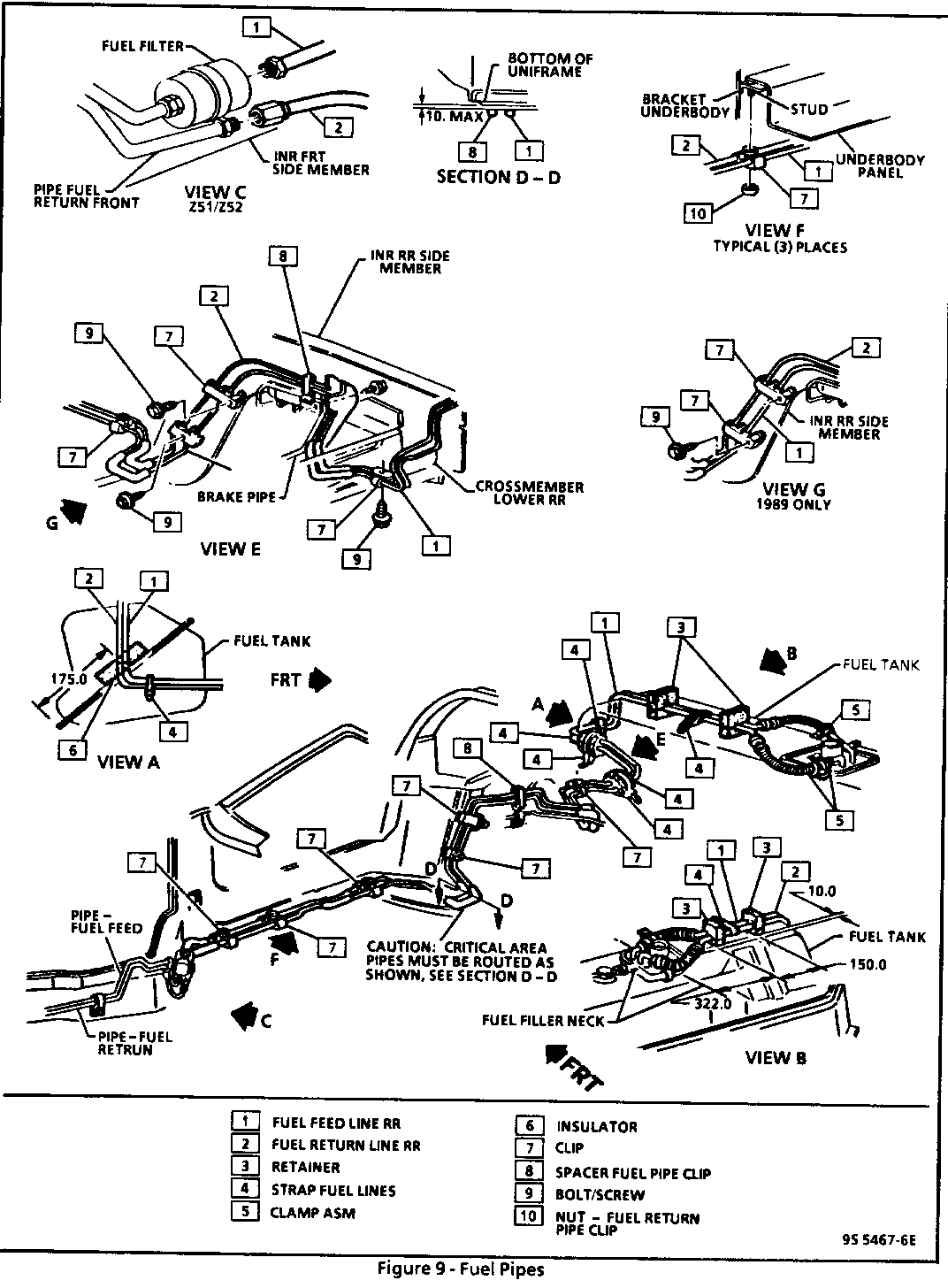
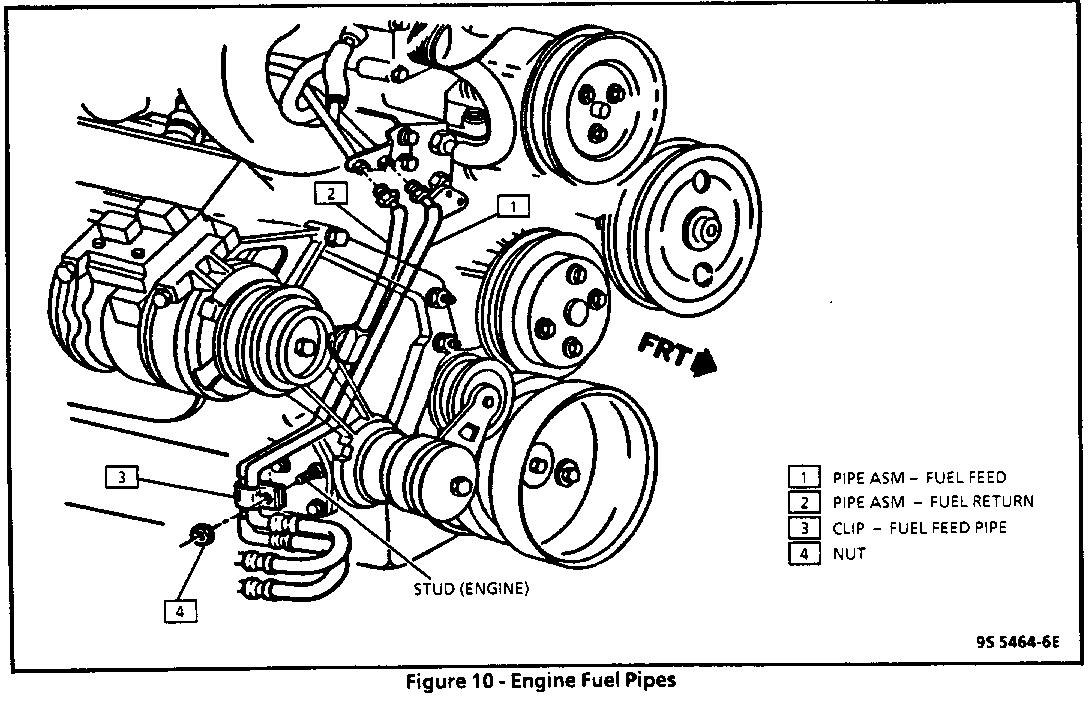
FUEL FEED AND RETURN PIPE/HOSE ASSEMBLIES REPLACEMENT (Figures 9, 10) --------------------------------------------------------------------- NOTICE: When replacing fuel feed and return pipes, always replace them with original equipment or parts that meet the GM specifications for those parts. The replacement pipe must have the same type of fittings as the original pipes to ensure the integrity of the connection.
Do not use copper or aluminum tubing to replace steel tubing. Only tubing meeting the 124M specification or its equivalent is capable of meeting all pressure and vibration characteristics necessary to ensure the durability standard required.
Do not attempt to repair the fuel feed or return pipe assemblies. If either the hose or the pipe is damaged, replace the complete assembly.
When replacing fuel feed or return hoses always replace them with original equipment or parts meeting GM specifications, use only reinforced fuel-resistant hose which is identified with the word "Fluroelastomer" or "GM 6163-M" on the hose. Inside hose diameter must match outside pipe diameter.
Remove or Disconnect
1. Negative battery terminal.
2. Relieve fuel system pressure (see "Fuel System Pressure Relief').
3. Hardware retaining section of line to be replaced.
- Note location of attaching hardware for installation.
Important
o Always use a back-up wrench to support fuel rail fittings when removing fuel lines.
4. Fuel feed or return line.
Inspect
o 0-rings for cuts, distortion, or any signs of damage and replace as required.
o Hose portions of assembly for cuts, swelling, cracks and distortion. Replace as required.
o Pipe portion of assembly for bends, kinks, chafing and cracks. Replace as required.
Install or Connect
NOTICE: Pipes must be properly secured to the frame to prevent chafing. A minimum of 13 mm (1/2") clearance must be maintained around a pipe to prevent contact and chafing. A minimum of 19 mm (4") clearance must be maintained around any moving part.
Fuel pipes must not contact the fuel tank or underbody at any point.
Important
o Follow the same routing as the original pipe.
o Hoses and pipes must be properly secured to prevent chafing.
o Always use a back-up wrench to support fuel rail fittings when installing fuel lines.
1. Reverse removal procedure.
Tighten
o Fuel line fittings to 30 N-m (22 lb. ft.).
2. Tighten fuel filler cap.
3. Negative battery terminal.
Inspect
o Turn ignition switch to "ON," position for two seconds, then turn to "OFF" for five seconds. Again turn to"ON" position, and check for fuel leaks.
FUEL VAPOR PIPES AND HOSES REPAIR/ REPLACEMENT ---------------------------------------------- NOTICE: When replacing or repairing vapor pipes, always replace them with original equipment or parts that meet the GM specifications for those parts. The replacement pipe must have the same type of fittings as the original pipes to ensure the integrity of the connection.
Do not use copper or aluminum tubing to replace steel tubing. Only tubing meeting the 124M specification or its equivalent is capable of meeting all pressure and vibration characteristics necessary to ensure the durability standard required.
When replacing vapor hoses always replace them with original equipment or parts meeting GM specifications, use only reinforced fuel-resistant hose which is identified with the word "Fluroelastomer" or "GM 6163-M" on the hose. Inside-hose diameter must match outside pipe diameter.
Do not use rubber hose within 100mm (4") of any part of the exhaust system or within 254 mm (10") of the catalytic converter.
Remove or Disconnect
1. Hardware retaining section of pipe to be replaced.
- Note location of attaching hardware for installation.
2. Section of pipe and hoses.
Inspect
o Hoses for cuts, swelling, cracks and distortion. Replace as required.
o Pipes for bends, kinks and cracks. Repair or replace sections as required.
- In the repairable areas, cut a piece of fuel hose 100 mm (4") longer than portion of the line removed. If more than a 152 mm (6") length of pipe is removed, use a combination of steel pipe and hose so that the total hose lengths, including the 100 mm (4") additional length will not be more than 254 mm (10") long.
Install or Connect
Important
o Follow the same routing as the original hoses and pipes.
o Hoses and pipes must be properly secured to prevent chafing.
o Reverse removal procedure.
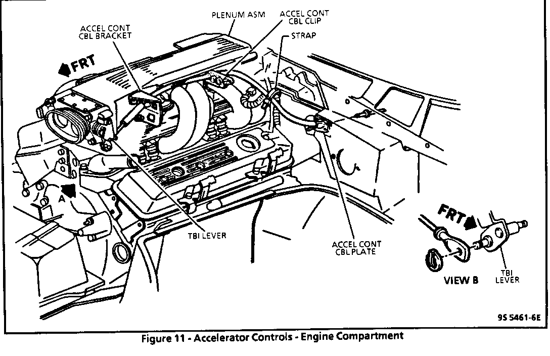
ACCELERATOR CONTROL CABLE (Figures 11, 12)
Remove or Disconnect
1. Lower instrument panel trim attaching screws (3), retaining clip and lower instrument panel trim.
- Partially drop lower instrument panel trim and disconnect courtesy light.
2. Accelerator cable from accelerator pedal.
3. Squeeze accelerator cable cover tangs and push cable through dash panel (bulkhead).
4. Accelerator cable routing strap.
5. Release accelerator cable clip and remove accelerator cable.
NOTICE: The accelerator cam is made of steel and is spring loaded. Care should be taken not to damage accelerator cable cam on throttle body when removing cable.
6. Turn accelerator cable cam clockwise and hold.
- Slide accelerator cable off accelerator cam.
7. Squeeze accelerator cable cover tangs and push cable through accelerator cable bracket.
Install or Connect
NOTICE: To prevent possible interference, flexible components (hoses, wires, conduits, etc.) must not be routed within 50 mm (2") of moving parts unless routing is positively controlled.
1. Reverse removal procedure.
Inspect
o Check for complete throttle opening and closing positions by operating accelerator pedal. Also check for poor carpet fit under the accelerator pedal. Throttle should operate freely without bind between full closed and wide open throttle.
2. Apply heavy bodied sealer around accelerator cable at engine compartment of dash panel (bulkhead).
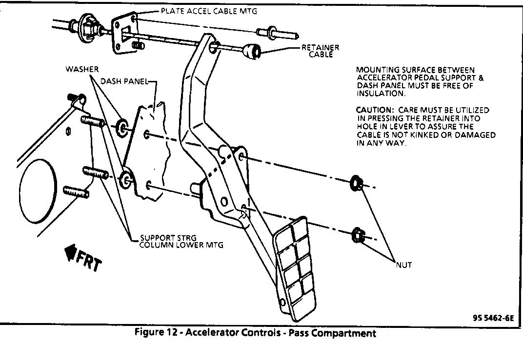
ACCELERATOR PEDAL (Figures 11, 12)
Remove or Disconnect
1. Lower instrument panel trim attaching screws (3), retaining clip and lower instrument panel trim.
- Partially drop lower instrument panel trim and disconnect courtesy light.
2. Accelerator cable from accelerator pedal.
3. Accelerator pedal attaching nuts (2) and accelerator pedal.
Install or Connect
Important
o The mounting surface between support and dash panel must be free of insulation. The carpet and padding in pedal and tunnel area must be positioned to lay flat and be free of wrinkles and bunches.
1. Accelerator pedal and attaching nuts (2).
Tighten
o Accelerator pedal attaching nuts to 8 N-m (71 lb. in.).
2. Accelerator cable on accelerator pedal.
Inspect
o Check for complete throttle opening and closing positions by operating accelerator pedal. Also check for poor carpet fit under the accelerator pedal.
o Throttle should operate freely without bind between full closed and wide open throttle.
3. Courtesy light to lower instrument panel trim.
- Lower instrument panel trim, lower instrument panel trim attaching screws (3) and retaining clip.
TORQUE SPECIFICATIONS
Fuel Line Fittings . . . . . . . . . . 30.0 N.m (22 lb. ft.) Fuel Level Meter Assembly Attaching Screws . . . . . . . . . . . . 4.5 N.m (40 lb. in.) Front Fuel Tank Retaining Strap Bolts . . . . . . . . . . . . . . . . . . . . 14.5 N.m (20 lb. ft.) Rear Fuel Tank Retaining Strap Nuts . . . . . . . . . . . . . . . . . . . . 4.5 N.m (40 lb. in.)
Fuel Tank Cable Attaching Bolts . . . 20.0 N.m (15 lb. ft.)
Accelerator Pedal Attaching Nuts . . . . . . . . 8 N.m (71 lb. in.)
General Motors bulletins are intended for use by professional technicians, not a "do-it-yourselfer". They are written to inform those technicians of conditions that may occur on some vehicles, or to provide information that could assist in the proper service of a vehicle. Properly trained technicians have the equipment, tools, safety instructions and know-how to do a job properly and safely. If a condition is described, do not assume that the bulletin applies to your vehicle, or that your vehicle will have that condition. See a General Motors dealer servicing your brand of General Motors vehicle for information on whether your vehicle may benefit from the information.
