M/T ON CAR SERVICE W/6-SPEED M/T MANUAL UPDATE

Model and Year: 1989 CORVETTE WITH 6-SPEED MANUAL TRANSMISSION
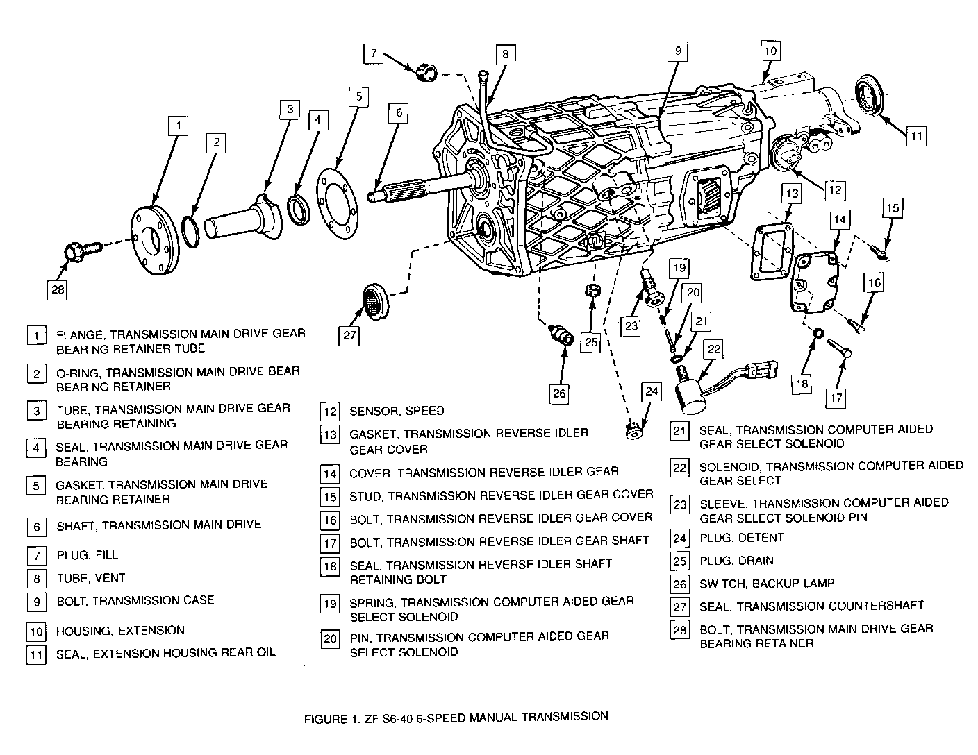
IMPORTANT: THE PROCEDURES CONTAINED IN THIS BULLETIN COVER THE REPAIR OF COMPONENTS THAT ARE SERVICEABLE BY THE DEALER UNDER THE ZF S6-40 SIX SPEED MANUAL TRANSMISSION EXCHANGE PROGRAM. NO REPAIRS OF COMPONENTS OTHER THAN THOSE OUTLINED IN THESE PROCEDURES ARE ALLOWED. (Figure 1)
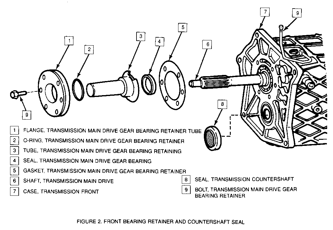
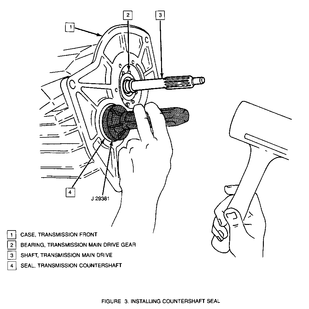
COUNTERSHAFT SEAL (Figures 2 and 3)
1. Disconnect battery negative cable 2. Raise vehicle 3. Remove transmission - Refer to Section 7B, "ZF S6-40 Manual Transmission" in the 1989 Corvette Service Manual 4. Remove countershaft seal from case 5. Install countershaft seal into case using J29381 6. Install transmission 7. Lower vehicle 8. Connect battery negative cable
TRANSMISSION MAIN DRIVE GEAR BEARING RETAINER AND GASKET (Figure 2)
1. Disconnect battery negative cable 2. Raise vehicle 3. Remove transmission - Refer to Section 7B, "ZF S6-40 Manual Transmission" in the 1989 Corvette Service Manual 4. Remove bearing retainer assembly from transmission 5. Clean front case and bearing retainer sealing surfaces 6. Install retainer gasket, retainer assembly and bolts 7. Tighten bolts to 21 N.m. (15 lbs. ft.) 8. Install transmission 9. Lower vehicle 10. Connect battery negative cable
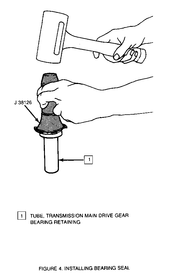
TRANSMISSION MAIN DRIVE GEAR BEARING SEALS (Figures 2 and 4)
1. Disconnect battery negative cable 2. Raise vehicle 3. Remove transmission - Refer to Section 7B, "ZF S6-40 Manual Transmission" in the 1989 Corvette Service Manual 4. Remove bearing retainer assembly from transmission 5. Separate retainer flange from bearing retainer assembly 6. Remove o-ring from flange 7. Gently pry main drive gear bearing seal from retainer tube and discard seal 8. Clean front case and bearing retainer sealing surfaces Retaining tube surface onto which bearing seal seats 9. Install bearing seal into retaining tube using J38126 10. Install o-ring onto flange 11. Install Tube into flange 12. Install Retainer, gasket, retainer assembly and bolts 13. Tighten bolts to 21 N.m. (15 lbs. ft.) 14. Install transmission 15. Lower vehicle 16. Connect battery negative cable
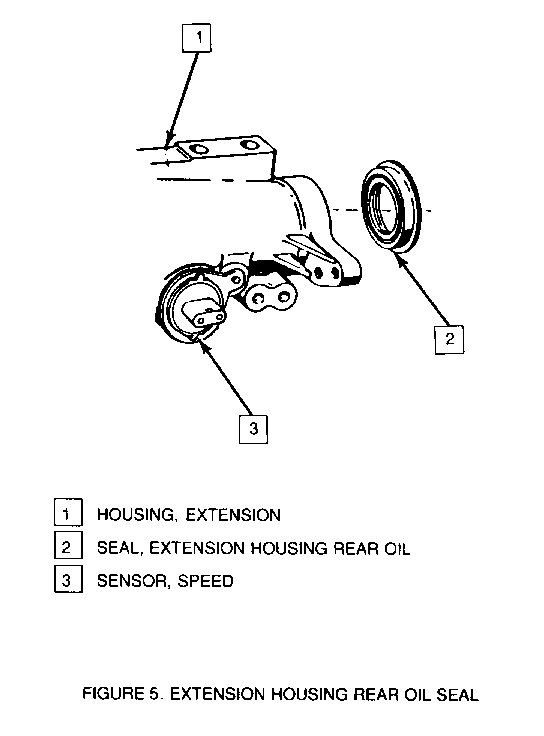
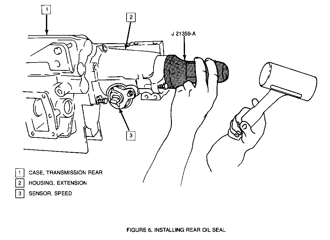
EXTENSION HOUSING REAR OIL SEAL (Figure 5 and 6)
1. Remove complete exhaust assembly. Refer to Section 6F, "Exhaust System" in the 1989 Corvette Service Manual 2. Remove propeller shaft. Refer to Section 4A, "Propeller Shaft and Universal Joints", in the 1989 Corvette Service Manual 3. Work around seal perimeter and pry out seal a small amount at a time, until completely released 4. Install seal using J21359-A 5. Install propeller shaft 6. Check transmission oil level 7. Tighten fill plug to 50 N.m. (37 lbs. ft.) 8. Install complete exhaust assembly
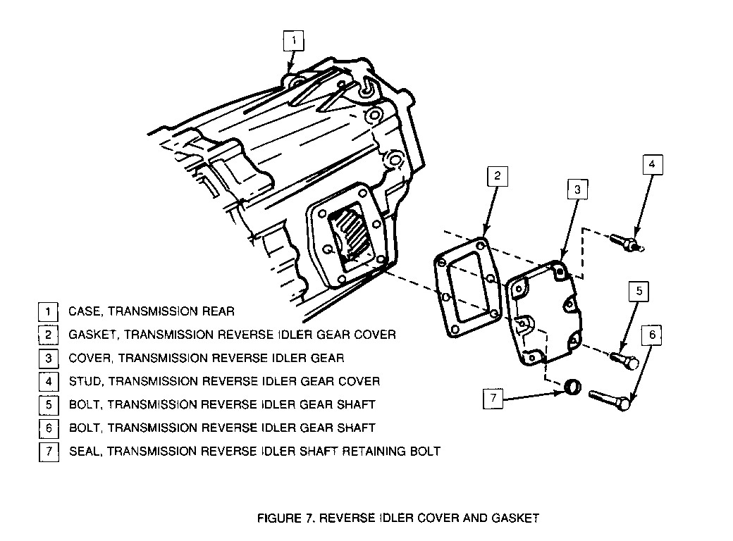
REVERSE IDLER GEAR COVER GASKET (Figure 7)
1. Raise vehicle 2. Drain transmission fluid 3. Tighten drain plug to 50 N.m. (37, lbs. ft.) 4. Remove idler cover bolts, including reverse idler shaft bolt 5. Remove sealing washer from reverse idler shaft bolt 6. Remove cover and gasket
IMPORTANT: REVERSE IDLER GEAR SHAFT BOLT MUST BE REINSERTED INTO SHAFT WHEN COVER IS REMOVED TO PREVENT SHAFT ROTATION.
7. Clean rear case housing and idler gear cover sealing surfaces 8. Install sealing washer onto reverse idler shaft bolt 9. Install cover and gasket 10. Install cover bolts, including reverse idler shaft bolt 11. Tighten idler cover and idler shaft bolts to 21 N.m. (15 lbs. ft.) 12. Refill transmission 13. Tighten fill plug to 50 N.m. (37 lbs. ft.) 14. Lower vehicle
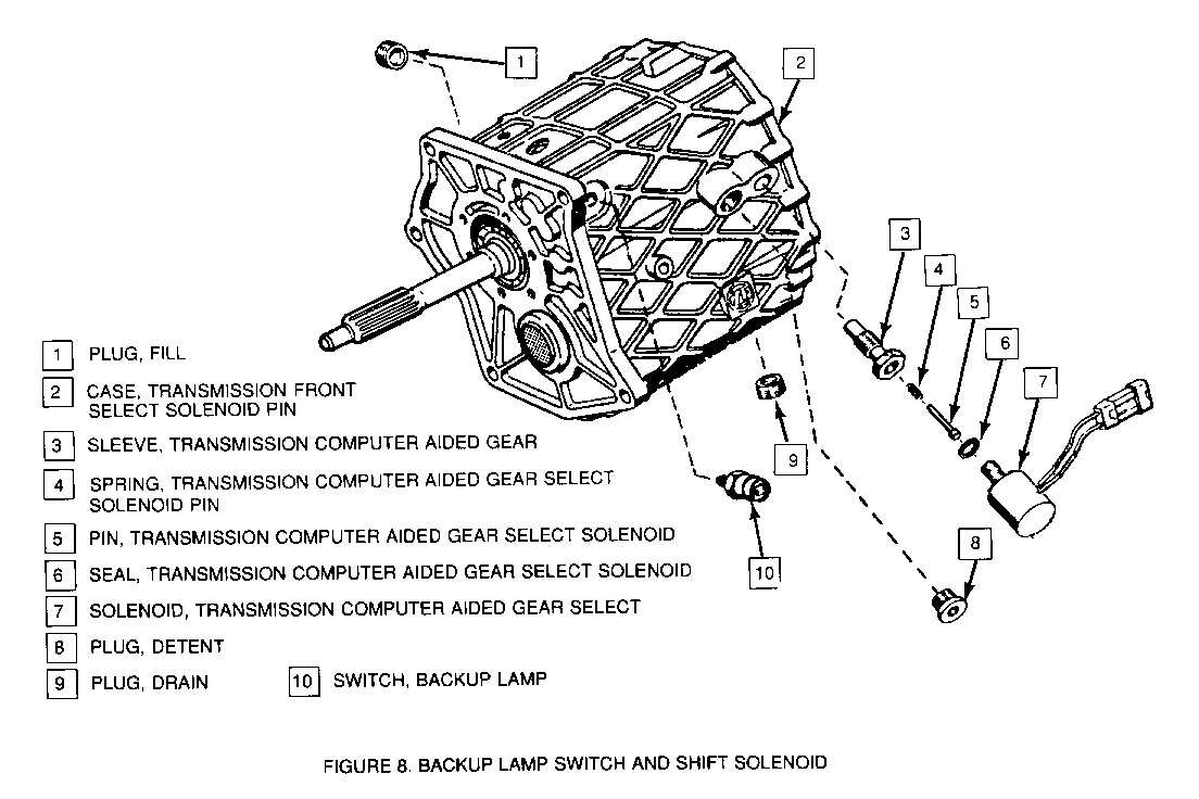
SHIFT SOLENOID ASSEMBLY (Figure 8)
1. Disconnect battery negative cable 2. Raise vehicle 3. Disconnect electrical lead from solenoid 4. Remove solenoid 5. Install solenoid 6. Tighten solenoid to 25 N.m. (18 lbs. ft.) 7. Connect electrical lead onto solenoid 8. Lower vehicle 9. Connect battery negative cable
BACKUP LAMP SWITCH (Figure 8)
1. Disconnect battery negative cable 2. Raise vehicle 3. Disconnect electrical connector from switch 4. Remove backup lamp switch 5. Install backup lamp switch 6. Tighten switch to 47 N.m. (35 lbs. ft.) 7. Connect electrical connector onto switch 8. Lower vehicle 9. Connect battery negative cable
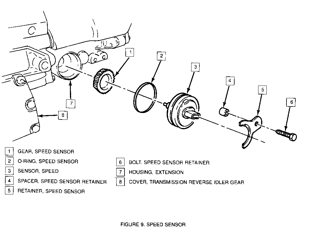
SPEED SENSOR (Figures 5 and 9)
1. Disconnect battery negative cable 2. Raise Vehicle 3. Disconnect electrical connector from sensor 4. Remove sensor retainer bolt, retainer, and spacer 5. Remove sensor 6. Remove o-ring and gear from sensor 7. Install o-ring and gear onto sensor 8. Install sensor 9. Install sensor spacer, retainer, and bolt 10. Tighten bolt to 10 N.m. (89 lbs. in.) 11. Connect electrical connector onto sensor 12. Lower vehicle 13. Connect battery negative cable
TRANSMISSION OIL DRAIN/FILL (Figure 1) --------------------------- 1. Disconnect battery negative cable 2. Raise vehicle 3. Remove drain plug and allow fluid to drain completely 4. Install drain plug 5. Tighten drain plug to 50 N.m. (37 lbs. ft.) 6. Remove fill plug and fill transmission with 2.12 liters of manual transmission fluid, GM P/N 1052931
IMPORTANT: TRANSMISSION SHOULD BE IN HORIZONTAL POSITION AND FILLED TO POINT OF OVERFLOW.
7. Install fill plug 8. Tighten fill plug to 50 N.m. (37 lbs. ft.) 9. Lower vehicle 10. Connect battery negative cable
TOROUE SPECIFICATIONS
Bolt, Transmission Case......................... 25 N.m (18 lbs. ft.) Bolt, Bearing Retainer.......................... 21 N.m (15 lbs. ft.) Stud, Transmission Reverse Idler Gear Cover..... 21 N.m (15 lbs. ft.) Bolt, Transmission Reverse Idler Gear Cover..... 21 N.m (15 lbs. ft.) Bolt, Transmission Reverse Idler Gear Shaft..... 21 N.m (15 lbs. ft.) Bolt, Speed Sensor Retainer..................... 10 N.m (89 lbs. ft.) Plug, Detent.................................... 35 N.m (26 lbs. ft.) Plug, Drain..................................... 50 N.m (37 lbs. ft.) Plug, Fill...................................... 50 N.m (37 lbs. ft.) Tube, Vent...................................... 15 N.m (11 lbs. ft.) Solenoid, Transmission Computer Aided Gear Select............................. 25 N.m (18 lbs. ft.) Switch, Backup Lamp............................. 47 N.m (35 lbs. ft.)
GENERAL SPECIFICATIONS
Transmission Fluid Capacity....................... 2.12 Liters
General Motors bulletins are intended for use by professional technicians, not a "do-it-yourselfer". They are written to inform those technicians of conditions that may occur on some vehicles, or to provide information that could assist in the proper service of a vehicle. Properly trained technicians have the equipment, tools, safety instructions and know-how to do a job properly and safely. If a condition is described, do not assume that the bulletin applies to your vehicle, or that your vehicle will have that condition. See a General Motors dealer servicing your brand of General Motors vehicle for information on whether your vehicle may benefit from the information.
