SERVICE MANUAL UPDATE-SEC. 5E2 ABS/ASR SYS., REV. DTC 65 DIAG

Subject: ANTI-LOCK BRAKE/ASR SYSTEM, REVISED DIAGNOSTIC TROUBLE CODE 65 CHART
Model and Year: 1992-93 CORVETTE
The attached revised DTC 65 diagnostic chart information should be used when diagnosing DTC 65 for the ABS/ASR System on 1992 and 1993 Corvettes.
DTC 65 ADJUSTER ASSEMBLY MALFUNCTION
Circuit Description:
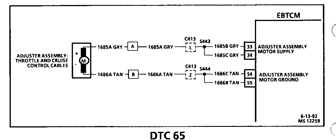
The adjuster assembly circuit provides both power and ground to the adjuster assembly to help control engine torque during an ASR event.
DTC 65 will set if CKT 1685 or CKT 1686 are shorted to ground, shorted to B +, shorted to each other, or both open at the same time. The ASR system will be disabled for the remainder of the ignition cycle and the "SERVICE ASR" lamp will illuminate.
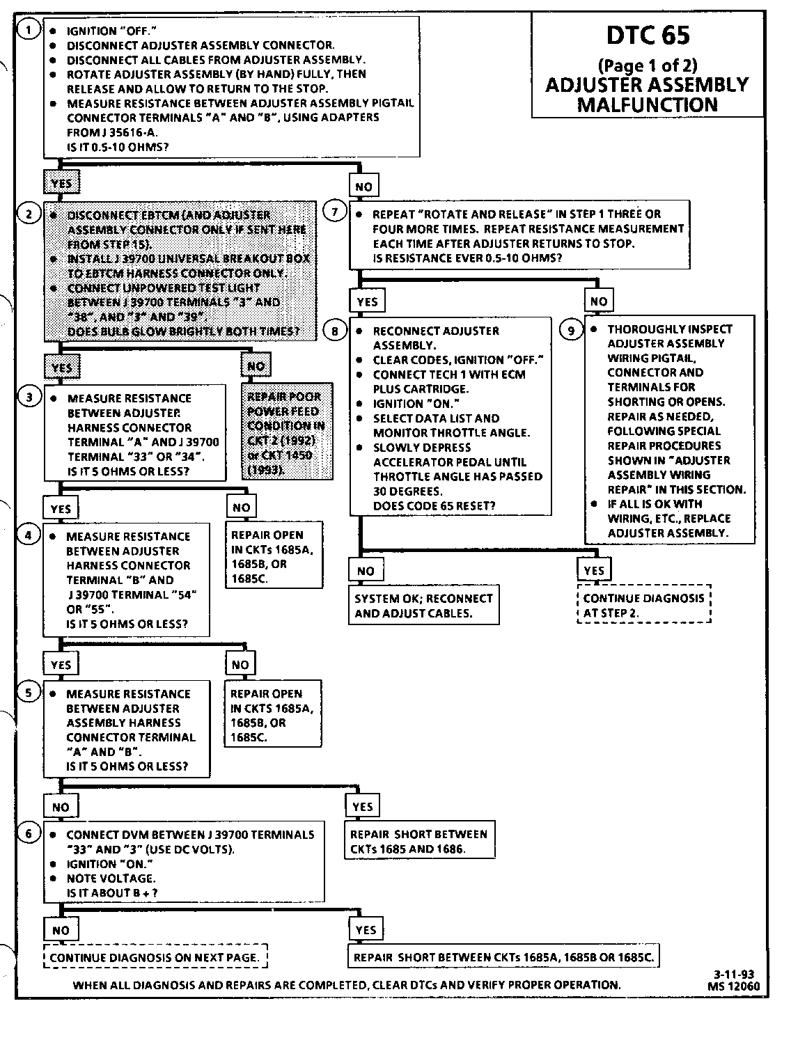
Test Description: Number(s) below refer to for circled number(s) on the diagnostic chart.
1. Checks for proper adjuster assembly motor winding resistance. It is very important to do the "rotate & release" procedure before measuring to allow the motor to reach the "home" position. 2. Checks for a poor power feed to the EBTCM through CKT 2 (1992) or CKT 1450 (1993), which may be sensed by the EBTCM to be an open. 3. Checks for open(s) in CKT 1685B and/or 1685C. 4. Checks for open(s) in CKT 1686B and/or 1686C. 5. Checks for a short between CKTs 1685 and 1686. 6. Checks for short(s) to B+ in CKT 1685B and/or 1685C. 7. Repeats "rotate & release " procedure from Step 1. The adjuster assembly resistance should be 0.5-10 ohms at least once after the "rotate and release" procedure. 8. Sets throttle to a position which enables one of the EBTCMs special monitoring systems of the adjuster assembly circuits, checking for a DTC reset. 9. Checks wiring and connectors for intermittents and/or shorts. Information given under "Intermittents and Poor Connections"in SECTION 8A-4 details conditions which can cause intermittents and how to identify them. The adjuster assembly requires special wiring repair procedures. Use only the instructions as shown under "Adjuster Assembly Wiring Repair" in this section if wiring repairs on the adjuster assembly are needed.
DIAGNOSTIC AIDS:
It is very important that a thorough inspection of the wiring and connectors be performed. Failure to carefully and fully inspect wiring and connectors may result in misdiagnosis, causing part replacement with reappearance of the fault.
If the "SERVICE ABS," "SERVICE ASR," "ABS ACTIVE," "ASR ACTIVE," and "ASR OFF" indicators all come "ON" when the ignition is turned "ON" but do not turn "OFF" after a few seconds (bulb check). Check for a poor connection or an open in ground CKT 801, especially at the connection point to the engine. DTC 65 ADJUSTER ASSEMBLY MALFUNCTION
Circuit Description:
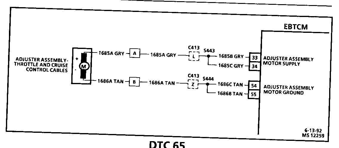
The adjuster assembly circuit provides both power and ground to the adjuster assembly to help control engine torque during an ASR event.
DTC 65 will set if CKT 1685 or CKT 1686 are shorted to ground, shorted to B +, shorted to each other, or both open at the same time. The ASR system will be disabled for the remainder of the ignition cycle and the "SERVICE ASR" lamp will illuminate.
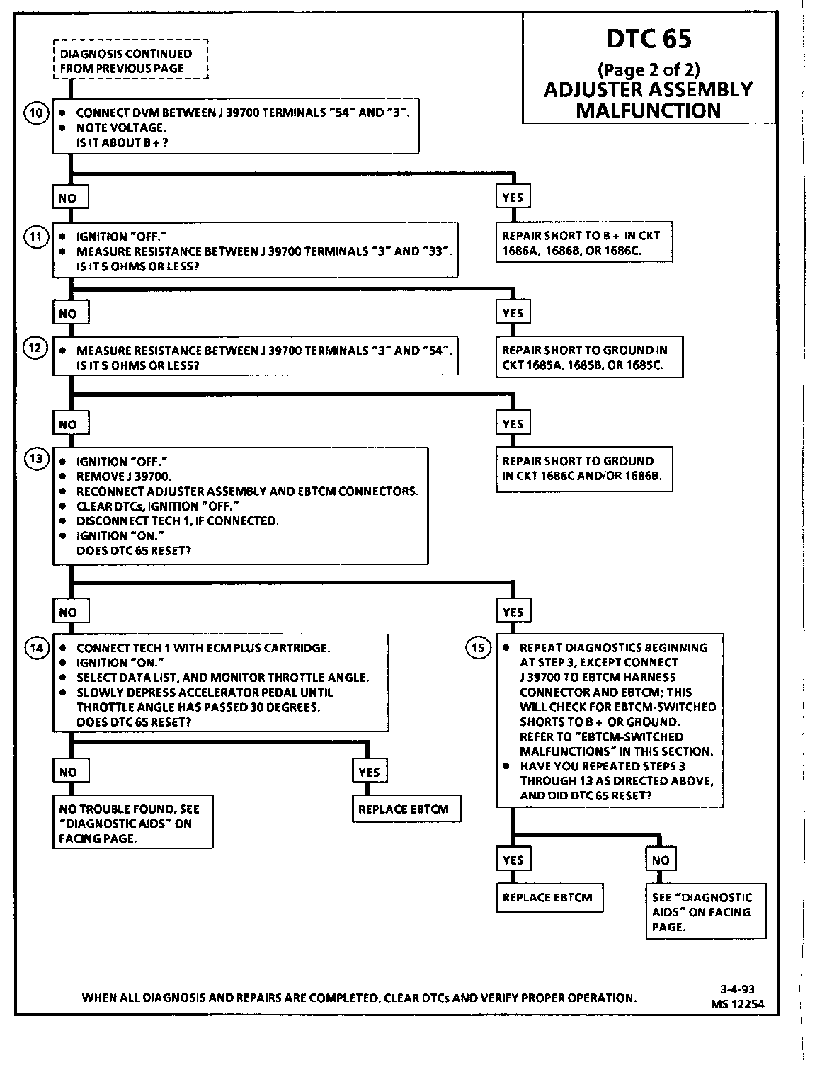
Test Description: Number(s) below refer to circled number(s) on the diagnostic chart.
10. Checks for short(s) to B+ in CKT 1686B and/or 1686C.
11. Checks for short(s) to ground in CKT 1685B and/or 1685C.
12. Checks for short(s) to ground in CKT 1686B and/or 1686C.
13. Checks for continued DTC setting after wiring and adjuster assembly inspections.
14. Sets throttle to a position which enables one of the EBTCM's special monitoring systems of the adjuster assembly circuits, checking for a DTC reset. If the DTC resets, the EBTCM is likely at fault.
15. Checks for shorts to B+ or ground that are EBTCM-switched. If you have reached Step 15 for a second time after performing checks for EBTCM switched faults, the EBTCM is likely at fault for the DTC reset.
DIAGNOSTIC AIDS:
It is very important that a thorough inspection of the wiring and connectors be performed. Failure to carefully and fully inspect wiring and connectors may result in misdiagnosis, causing part replacement with reappearance of the fault.
If the "SERVICE ABS," "SERVICE ASR," "ABS ACTIVE," "ASR ACTIVE," and "ASR OFF" indicators all come "ON" but do not turn "OFF" after a few seconds (bulb check). Check for poor connection or open ground CKT 801, especially at the connection point to the engine.


General Motors bulletins are intended for use by professional technicians, not a "do-it-yourselfer". They are written to inform those technicians of conditions that may occur on some vehicles, or to provide information that could assist in the proper service of a vehicle. Properly trained technicians have the equipment, tools, safety instructions and know-how to do a job properly and safely. If a condition is described, do not assume that the bulletin applies to your vehicle, or that your vehicle will have that condition. See a General Motors dealer servicing your brand of General Motors vehicle for information on whether your vehicle may benefit from the information.
