SERVICE MANUAL UPDATE-SEC. 1C1 REV. DIAG. FOR DIAG. TROUBLE

SUBJECT: SERVICE MANUAL UPDATE - SECTION 1C1 - REVISED DIAGNOSTICS FOR DIAGNOSTIC TROUBLE CODE(S) 01 AND 02
VEHICLES AFFECTED: 1991-1993 'Y' MODEL
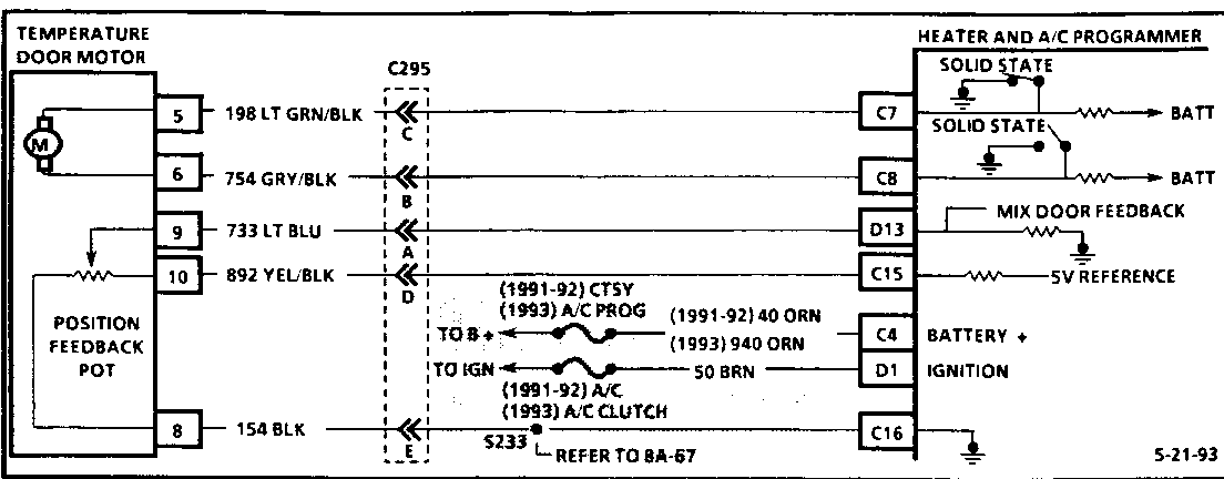
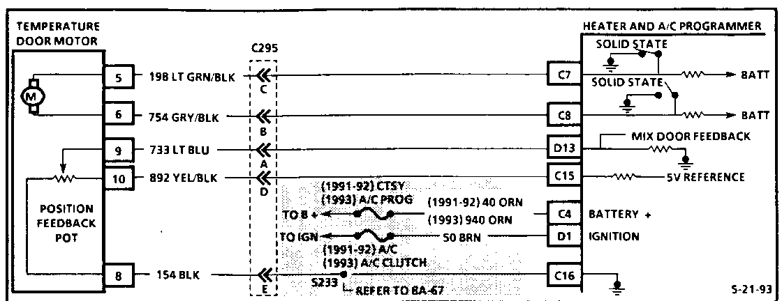
The diagnostics for DTC(S) 01 and 02 for 1991, 1992 and 1993 Corvettes with C68 HVAC have changed. Please use the attached pages when diagnosing DTC(S) 01 and 02.
DTC(s) 01 AND 02 (Page 1 of 2) TEMPERATURE DOOR MOTOR CIRCUIT FAULT
Circuit Description:
The feedback Potentiometer (POT) sensor measures the position of the temperature door. The heater and A/C programmer uses this information to drive the temperature door motor. A low feedback voltage represents a hot temperature door position and high feedback voltage represents a cold temperature door position. If DTC(S) 01 and 02 have been set, the programmer will enter a default value of 128 counts (mid position) so driver may still control full hot and full cold.
Important
o The A/C programmer logic will be lost if the A/C Prog and A/C Clutch fuses or the negative battery cable are removed with the ignition in the "ON" position. The programmer logic will be restored by removing the negative battery cable and reinstalling after 1 minute.
Test Description: Number(s) below refer to circled number(s) on the diagnostic chart.
DTC(s) 01-02 indicate the programmer has seen a fault at "D13".
OR
Mix motor/door will not go to the hot or cold position when programmer commands it, causing the programmer to see low or high voltage feedback from the POT.
1. This test eliminates the possibility of a false DTC being set. With the ignition "OFF," removing the negative battery cable and installing after 1 minute will clear the programmer memory.
2. This test will determine if the HVAC programmer is commanding the temperature door motor to travel its entire range. If parameter 34 is not within the specified range, full hot and full cold, the programmer should be replaced
3. This test will determine if the temperature door is actually going to its commanded position. Parameter 24 is linear to parameter 34 (desired vs. actual mix door position).
4. This test visually confirms that the temperature door is actually moving.
5. This test is to determine if the temperature door motor potentiometer is within the specified resistance range for full hot and full cold door position. If temperature door motor is not within the specified range, Step 6 should be performed before replacing the motor.
6. This test will determine if the temperature motor is receiving operating voltage from the programmer. If approximately 8 volts are present at C295, the temperature door motor is suspect.
Diagnostic Aids:
o If DTC 01 or 02 are intermittent, check connectors and wire harness for possible open or short.
o If the temperature door has free play greater than 5 mm (0.2 in.), replace the heater case components in the following order until free play greater than 5 mm (0.2 in.) no longer exists.
1) Temperature door motor adapter (temp valve adapter.)
2) Temperature door motor (actuator.)
3) Temperature door (temperature valve.)
4) Heater case cover.
DTC(s) 01 AND 02 (Page 2 of 2) TEMPERATURE DOOR MOTOR CIRCUIT FAULT
Circuit Description:
The feedback Potentiometer (POT) sensor measures the position of the temperature door. The heater and A/C programmer uses this information to drive the temperature door motor. A low feedback voltage represents a hot temperature door position and high feedback voltage represents a cold temperature door position. If DTC(S) 01 and 02 have been set, the programmer will enter a default value of 128 counts (mid position) so driver may still control full hot and full cold.
Important
o The A/C programmer logic will be lost if the A/C Prog and A/C Clutch fuses or the negative battery cable are removed with the ignition in the "ON" position. The programmer logic will be restored by removing the negative battery cable and reinstalling after 1 minute.
Test Description: Number(s) below refer to circled number(s) on the diagnostic chart.
DTC(s) 01-02 indicate the programmer has seen a fault at "D13".
OR
Mix motor/door will not go to the hot or cold position when programmer commands it, causing the programmer to see low or high voltage feedback from the POT.
7. This test will determine if the temperature door is misaligned causing the temperature door motor potentiometer resistance to be outside the specified range.
8. This test will determine if there is output voltage at the programmer to activate the temperature door motor. If voltage is present at the programmer and not at C295, an open exists in the circuit. If no voltage is present at the programmer, it should be replaced.
Diagnostic Aids:
o If DTC 01 or 02 are intermittent, check connectors and wire harness for possible open or short.
o If the temperature door has free play greater than 5 mm (0.2 in.), replace the heater case components in the following order until free play greater than 5 mm (0.2 in.) no longer exists.
1) Temperature door motor adapter (temp valve adapter.)
2) Temperature door motor (actuator.)
3) Temperature door (temperature valve.)
4) Heater case cover.


General Motors bulletins are intended for use by professional technicians, not a "do-it-yourselfer". They are written to inform those technicians of conditions that may occur on some vehicles, or to provide information that could assist in the proper service of a vehicle. Properly trained technicians have the equipment, tools, safety instructions and know-how to do a job properly and safely. If a condition is described, do not assume that the bulletin applies to your vehicle, or that your vehicle will have that condition. See a General Motors dealer servicing your brand of General Motors vehicle for information on whether your vehicle may benefit from the information.
