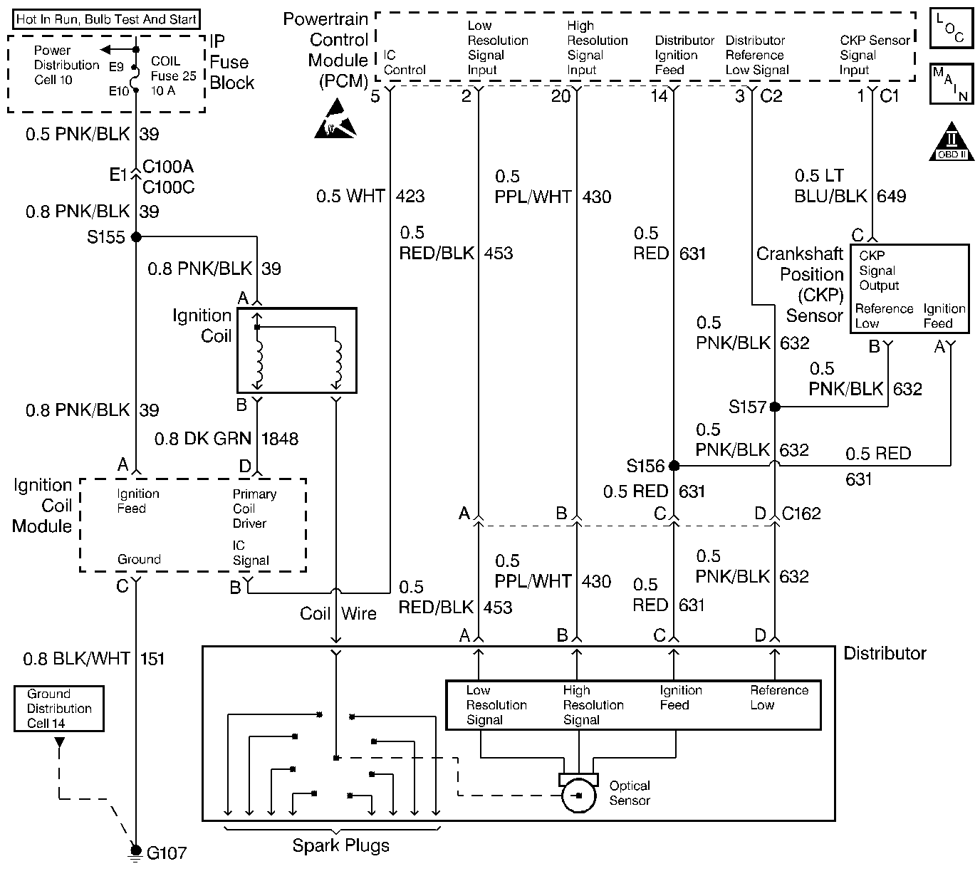
Diagnostic Aids
An ignition coil wire that is open or shorted to ground can cause a no start condition.
Test Description
Number(s) below refer to step number(s) on the diagnostic table.
Important:: The battery should be fully charged prior to any tests.
-
Checks for proper output from the distributor ignition system. The spark tester requires a minimum of 25,000 volts to fire. This check can be used in case of an ignition miss, because the system may provide enough voltage to run the engine but not enough to fire a spark plug under heavy load.
-
This test will separate the distributor cap, rotor and ignition wires from the ignition coil to help identify a secondary ignition system problem. It is necessary to unscrew the top terminal on the ST-125 spark tester for a proper fit in the distributor end of the coil wire.
-
This will determine if the proper available voltage exists in the primary ignition circuit.
-
This check will begin to determine if the PCM is providing a signal to the ignition coil module or not. If the PCM is not providing a signal to the ignition coil module, the problem exists between the distributor and PCM.
-
If the PCM is detecting low resolution signal pulses and no IC signal was available at the ignition coil module, a problem exists with the PCM or the circuit to the ignition coil module.
-
If the PCM does not detect low resolution signal pulses, the distributor or distributor to PCM circuitry is most likely the problem. The remaining tests will determine if the proper signals are being sent and received from both the distributor and PCM.
-
A grounded coil circuit will cause the ignition fuse to open, and a no-start condition will occur.
Step | Action | Value(s) | Yes | No | ||||||
|---|---|---|---|---|---|---|---|---|---|---|
1 | Was the Powertrain On-Board Diagnostic (OBD) System Check performed? | -- | ||||||||
Important:: If no spark is coming from the ignition wire, check a second ignition wire. A few sparks and then nothing is considered no spark. Is spark jumping the gap at the spark tester? | -- | |||||||||
3 | Remove the spark plugs and inspect for being gas fouled. Are the spark plugs gas fouled? | -- | Go to Spark Plug Replacement | Go to Fuel System Diagnosis | ||||||
Is spark jumping the gap at the spark tester? | -- | |||||||||
Do both terminals measure less than the specified value? | 10.0V | |||||||||
6 | Is there only one terminal below the specified value? | 10.0V | ||||||||
Is the voltage between the specified values? | 1.0- 4.0 V | |||||||||
8 |
Did the test light illuminate? | -- | ||||||||
9 | Repair the Ignition Coil Module ground circuit. Is the repair completed? | -- | System OK | -- | ||||||
10 |
Was a poor connection found? | -- | System OK | |||||||
11 | Replace the Ignition Coil Module. Is the action completed? | -- | System OK | -- | ||||||
Is a low resolution signal indicated on the scan tool? | -- | |||||||||
Did the test light illuminate? | -- | |||||||||
14 | Using a DVM (J 39200), check for continuity between the distributor connector terminal D and ground. Does the circuit have continuity? | -- | ||||||||
15 | Using a DVM on the DC scale, measure the voltage at the distributor connector terminal A. Is the voltage at the specified value? | 5.0V | ||||||||
16 | Using a DVM on the DC scale, measure the voltage at the distributor connector terminal B. Is the voltage at the specified value? | 5.0V | ||||||||
17 | Faulty distributor connection or faulty distributor. Is the repair completed? | -- | System OK | -- | ||||||
18 |
Was a problem found and corrected? | -- | System OK | |||||||
19 | Inspect the secondary ignition wires for the following:
Was a problem found and corrected? | -- | System OK | |||||||
20 |
Was a problem found and corrected? | -- | System OK | |||||||
21 | Replace distributor base assembly. Refer to Distributor cap, Cover, Rotor and Base Assembly. Is the action complete? | -- | System OK | -- | ||||||
Check the ignition feed circuit to the coil for the following:
Did any of the above require a repair? | -- | System OK | ||||||||
23 |
Was an open or grounded circuit located? | -- | System OK | |||||||
24 | Replace the ignition coil. Is the action complete? | -- | System OK | -- | ||||||
25 |
Was a problem found and corrected? | -- | System OK | |||||||
26 |
Was a problem found and corrected? | -- | System OK | |||||||
27 |
Was a problem found and corrected? | -- | System OK | |||||||
28 |
Was a problem found and corrected? | -- | System OK | |||||||
29 |
Was a problem found and corrected? | -- | System OK | |||||||
30 | Check for a poor connection at the PCM and replace terminal if necessary. Was a problem found and corrected? | -- | System OK | |||||||
31 |
Important: Replacement PCM must be programmed. Refer to Powertrain Control Module Replacement/Programming . Replace the PCM. Is the action complete? | -- | System OK | -- |
