Removal Procedure
Caution: Provide additional support when a vehicle is on a hoist in the following
ways:
• Before removing parts, support the opposite end. This helps prevent
the vehicle from slipping off. • Before removing major components, chain the vehicle frame to the
hoist pads at the same end as the removal. This helps avoid a tip-off.
- Disconnect the negative battery cable.
- Relieve the fuel system pressure. Refer to the Fuel Pressure Relief Procedure.
- Drain the fuel tank. Refer to Draining Fuel Tank.
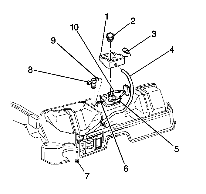
- Remove the filler door bezel attaching screws and the filler door bezel.
- Remove the fuel filler cap (2).
- Lift the fuel tank filler pipe housing (1) and disconnect the drain hose (4) from the nipple (3).
- Reinstall the fuel filler cap in order to prevent dirt and debris from entering the fuel tank.
- Remove the fuel tank filler pipe housing (1).
- Disconnect the fuel sender assembly electrical connector.
- Clean all the fuel connections and the surrounding areas before disconnecting the hoses in order to avoid possible contamination of the fuel system.
- Disconnect the fuel feed hose, the fuel return hose, and the EVAP hose from the fuel sender assembly.
- Remove the license plate and bracket to gain access for removal of the carriage bolts.
- Remove the backup lamp assemblies.
- Remove the inner stop lamp assemblies.
- Disconnect the outer stop lamp electrical connectors.
- Remove the high mount stop lamp socket.
- Remove the carriage bolts securing the fascia to the impact bar.
- Remove the upper rear fascia to the upper rear body panel bolts.
- Raise the vehicle on a hoist.
- Remove the spare tire and the tire carrier from the frame.
- Remove the underbody braces (convertible only).
- With the aid of an assistant, remove the exhaust system as an assembly from the rear of the converters.
- Remove the EVAP canister splash shield.
- Remove the lower body panel supports.
- Remove the wheelhouse liner panels.
- Disconnect the EVAP pipes from the EVAP canister.
- Remove the EVAP canister.
- Disconnect the fuel tank cables from the stabilizer shaft supports.
- Remove the attaching screws securing the bottom edge of the fascia to the energy absorber bracket.
- Remove the marker lamps.
- Remove the attaching nuts securing each side of the vertical outer retainer to the fascia.
- Remove the power antenna assembly from the mounting bracket.
- Remove the rear fascia.
- Remove the rear impact bar bolts.
- Loosen the front impact bar bolts.
- With the aid of an assistant, support the impact bar and remove the front impact bar bolts.
- Remove the impact bar and the fuel tank assembly.
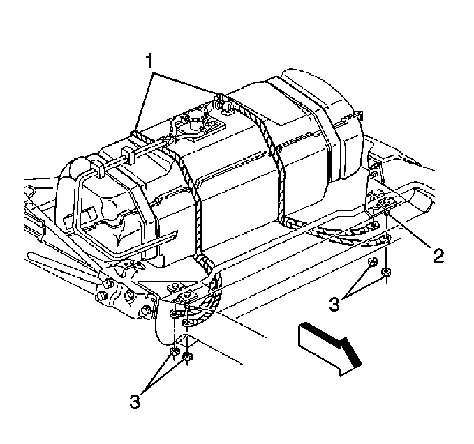
- Remove the fuel tank straps from the fuel tank and the impact bar.
- Remove the fuel tank from the impact bar.
- Remove the fuel tank cables (1) from the stabilizer shaft support bracket bolts (2).
- Remove the EVAP connections and the hose.
- Remove the fuel sender assembly.
Installation Procedure
- Install the fuel sender assembly.
- Install the EVAP connections and the hoses.
- Install the fuel tank cables (1) to the stabilizer shaft support bracket bolts (2).
- Install the fuel tank to the impact bar.
- Install the fuel tank straps to the fuel tank and the impact bar.
- With the aid of an assistant, install the impact bar and the fuel tank assembly.
- Install all the impact bar bolts.
- Install the rear fascia.
- Install the nuts to the vertical outer fascia retainers securing fascia to the body.
- Install the power antenna assembly to the mounting bracket.
- Install the nuts to each side of the fascia to the fascia horizontal retainer.
- Install the marker lamps.
- Install the screws securing the bottom edge of the fascia to the energy absorber bracket.
- Install the EVAP canister.
- Connect the hoses to the EVAP canister.
- Install both rear wheelhouse liner panels.
- Install the lower body panel supports.
- Install the canister splash shield.
- With the aid of an assistant, install the exhaust system as an assembly.
- Install the underbody braces (convertible only).
- Install the spare tire carrier and the spare tire to the frame.
- Lower the vehicle.
- Install the bolts securing the upper rear fascia to the upper rear body panel.
- Install the carriage bolts securing the fascia to the impact bar.
- Install the high mount stop lamp socket.
- Install the outer stop lamp electrical connectors.
- Install the inner stop lamp assemblies.
- Install the backup lamp assemblies.
- Install the license plate bracket and the license plate.
- Connect the fuel feed hose (10), the fuel return hose (5), and the EVAP hose (6) to the fuel sender.
- Connect the fuel sender electrical connector.
- Connect the drain hose (4) and install the fuel tank filler pipe housing (1).
- Refill the fuel tank.
- Install the fuel filler cap (2).
- Connect the negative battery cable.
- Inspect for leaks.
- Install the fuel filler door bezel.
Tighten
| • | Tighten the fuel tank strap bolts to 14.5 N·m (11 lb ft). |
| • | Tighten the fuel tank strap nuts to 4.5 N·m (40 lb in). |
Tighten
Tighten the impact bar bolts to 50 N·m (37 lb ft).
Tighten
Tighten the outer fascia retainer nuts to 6 N·m (53 lb in).
Tighten
Tighten the fascia retainer nuts to 6 N·m (53 lb in).
Install the fuel tank cables to the stabilizer shaft supports.
Tighten
Tighten the fuel tank cable nuts to 25 N·m (18 lb ft).
Tighten
| • | Tighten the underbody brace nuts to 27 N·m (20 lb ft). |
| • | Tighten the underbody brace bolts to 62.5 N·m (46 lb ft). |
| 37.1. | Turn the ignition switch ON for 2 seconds. |
| 37.2. | Turn the ignition switch OFF for 10 seconds. |
| 37.3. | Turn the ignition switch ON. |
| 37.4. | Check for fuel leaks. |
