For 1990-2009 cars only
Removal Procedure
- Disconnect the negative battery cable.
- Relieve the fuel system pressure. Refer to the Fuel Pressure Relief Procedure.
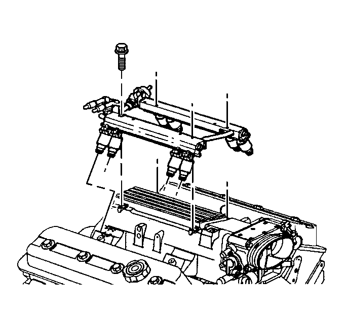
- Remove the fuel rail assembly. Refer to Fuel Rail Assembly.
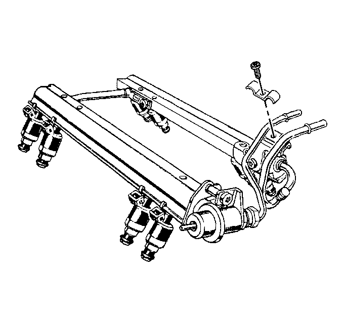
- Remove the inlet/outlet fuel tube retainer and the attaching screw.
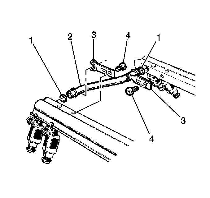
- Remove the crossover tube retainer attaching screws (4) and the crossover tube retainers (3).
- Remove the crossover tube (2) from the fuel rails.
- Remove the O-rings (1) from the crossover tube (2). Discard the O-rings.


Installation Procedure
- Lubricate the new crossover tube O-rings (1) with clean engine oil.
- Install the O-rings (1) on the crossover tube (2).
- Install the crossover tube (2) into the fuel rail sections.
- Install the crossover tube retainers (3) and the attaching screws (4).
- Install the inlet/outlet fuel tube retainer and the attaching screw.
- Install the fuel rail assembly. Refer to Fuel Rail Assembly.
- Tighten the fuel filler cap.
- Connect the negative battery cable.
- Inspect for leaks.

Tighten
Tighten the crossover tube retainer attaching screws to 5 N·m
(44 lb in).

Tighten
Tighten the inlet/outlet fuel tube retainer attaching screw to 5 N·m
(44 lb in).

| 9.1. | Turn the ignition switch ON for 2 seconds. |
| 9.2. | Turn the ignition switch OFF for 10 seconds. |
| 9.3. | Turn the ignition switch ON. |
| 9.4. | Check for fuel leaks. |
