Removal Procedure
- Drain the coolant. Refer to Cooling System Draining and Filling .
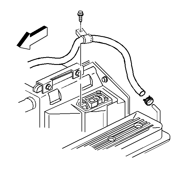
- Remove the clamp and the hose from the bleed pipe.
- Remove the left injector cover.
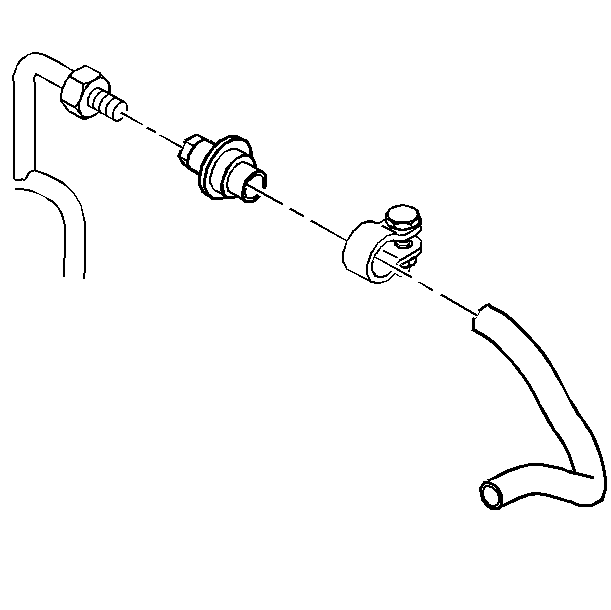
- Remove the clamp and the hose from the air check valve on the EGR supply pipe. Then, remove the check valve from the supply pipe (LT1 engine only).
- Remove the vacuum hose and the EGR valve from the intake manifold (LT1 engine only).
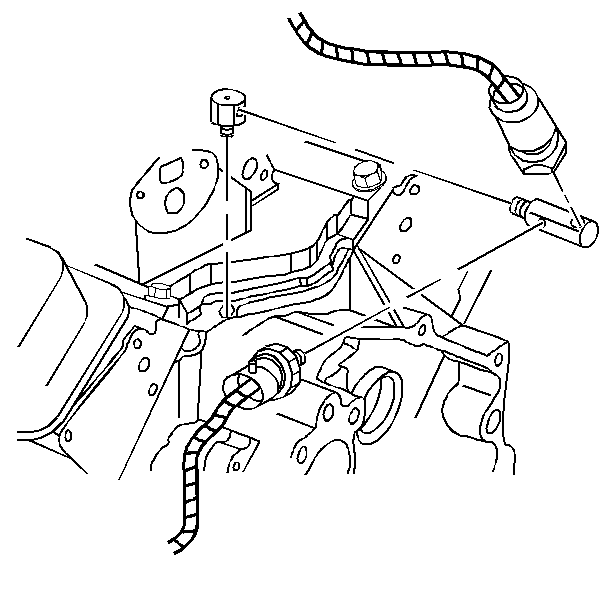
- Remove the electrical connectors on both of the oil pressure sensors.
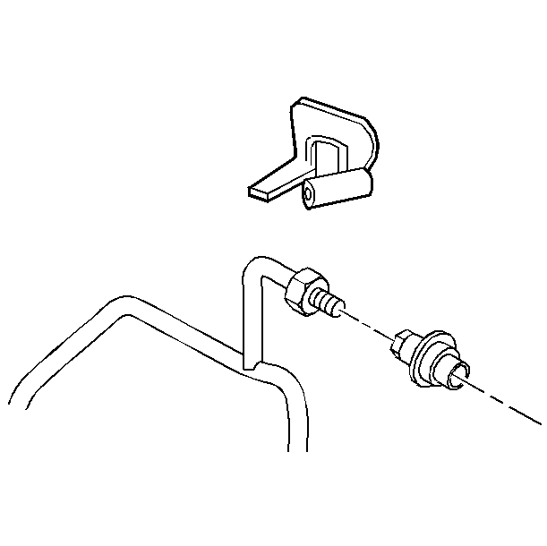
- Remove both oil pressure sensors and the adapter (1) from the T fitting at the rear of the engine block.
- Loosen the nut at the right rear intake manifold stud and remove the heat shield.
- Remove the retaining screw at the instrument panel wiring harness cutout. Move the harness aside in order to gain access to the bolt and the fitting at the right rear cylinder head.
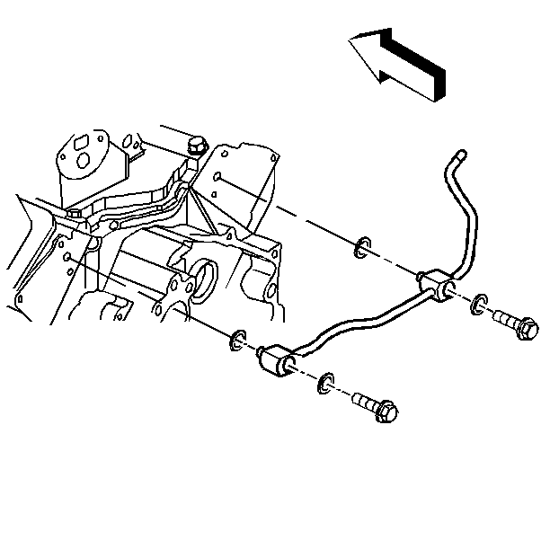
- Remove the bolts and the sealing washers at the rear of both of the cylinder heads.
- Remove the air bleed pipe from the vehicle.
- Clean any dirt and debris from the mating surfaces on the cylinder heads. Ensure that the passages in the banjo bolts are clean and not plugged.
- Inspect the air bleed pipe for any cracks or holes.
Notice: When adding coolant, use DEX-COOL® coolant. If silicated coolant is added to the system, premature engine, heater core or radiator corrosion may result. In addition, the engine coolant will require change sooner-at 50 000 km (30,000 mi) or 24 months.
Installation Procedure
- Install the air bleed pipe with the banjo bolts and the two sealing washers to the cylinder heads. Use two washers for each side of the cylinder heads.
- Reposition the wiring harness in the instrument panel. Install the mounting screws.
- Install the EGR supply pipe heat shield (LT1 engine only).
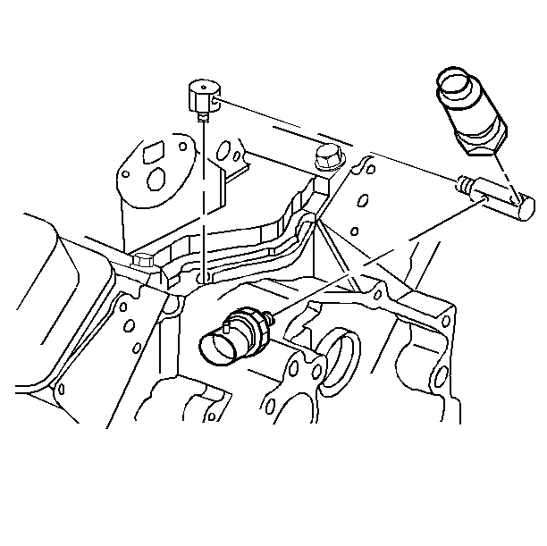
- Install the oil pressure adapter to the T fitting at the rear of the engine block. Install both of the oil pressure sensors (1) to the adapter. Install the smaller sensor to the inboard hole on the adapter.
- Install the electrical connector on both of the oil pressure sensors.
- Install the EGR valve with the gasket and the bolts (LT1 engine only).
- Install the vacuum hose to the EGR valve (LT1 engine only).
- Install the air check valve to the EGR supply pipe (LT1 engine only).
- Install the air hose and the clamp to the air check valve.
- Install the left side injector cover.
- Install the hose to the air bleed pipe. Tighten the clamp.
- Fill the cooling system. Refer to Cooling System Draining and Filling .
- Start the engine. Check for coolant leaks.

Tighten
The banjo bolts to 41 N·m (30 lb ft).
Notice: Use the correct fastener in the correct location. Replacement fasteners must be the correct part number for that application. Fasteners requiring replacement or fasteners requiring the use of thread locking compound or sealant are identified in the service procedure. Do not use paints, lubricants, or corrosion inhibitors on fasteners or fastener joint surfaces unless specified. These coatings affect fastener torque and joint clamping force and may damage the fastener. Use the correct tightening sequence and specifications when installing fasteners in order to avoid damage to parts and systems.

Tighten
The heat shield nut to 34 N·m (25 lb ft).


Tighten
The bolts to 22 N·m (16 lb ft).

Tighten
The check valve to 19 N·m (14 lb ft).

