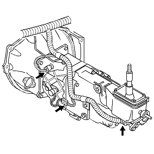
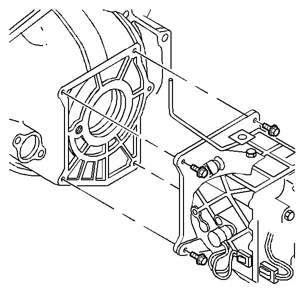
Removal Procedure
Notice: The service procedures found in this section cover the repair of the components that are serviceable by the dealer under the ZF S6-40 6 Speed Manual Transmission Exchange Program. No repairs of components other than those outlined in these procedures are allowed. Refer to updated service information for any revisions to the transmission exchange program. Should the transmission exchange program be discontinued refer to the Transmission/Transaxle/Transfer Case Unit Repair Manual (TURM) for overhaul procedures.
Notice: Before removing the transmission and the clutch housing assembly from the engine, the engine must be supported so as to prevent the vapor blow pipe assembly (located at the rear of the engine) from making contact with and damaging the dash panel.
- Disconnect the battery negative cable assembly from the battery
negative terminal. Refer to
Caution: Unless directed otherwise, the ignition and start switch must be in the OFF or LOCK position, and all electrical loads must be OFF before servicing any electrical component. Disconnect the negative battery cable to prevent an electrical spark should a tool or equipment come in contact with an exposed electrical terminal. Failure to follow these precautions may result in personal injury and/or damage to the vehicle or its components.
. - Remove the front floor console trim plate. Refer to SECTION 8C
- Raise and support the vehicle. Refer to Section 0A.
- Remove the complete exhaust system. Refer to General Exhaust System Replacement .
- Remove the parking brake cable guide from the driveline support.
- Support the transmission with a suitable jack.
- Remove the bolts retaining the driveline support.
- Slide the driveline support outboard in order to gain access to the propeller shaft.
- Remove the bolts retaining the gearshift support bracket.
- Remove the bolts retaining the propeller shaft to the yoke at the differential carrier and remove the propeller shaft.
- Slide the driveline support rearward until it makes contact with the rear exhaust hanger.
- Disconnect the following wire harness connectors:
- Remove the transmission to flywheel housing bolts
- Remove the transmission assembly from the vehicle
Important: Mark the position of the universal joint in relation to the differential carrier yoke before removal. This will maintain proper driveline balance.

| • | The backup lamp switch |
| • | The vehicle speed sensor |
| • | The computer aided gear select solenoid |

