Removal Procedure
- Disconnect the negative battery cable. Refer to
Caution: Unless directed otherwise, the ignition and start switch must be in the OFF or LOCK position, and all electrical loads must be OFF before servicing any electrical component. Disconnect the negative battery cable to prevent an electrical spark should a tool or equipment come in contact with an exposed electrical terminal. Failure to follow these precautions may result in personal injury and/or damage to the vehicle or its components.
in General Information. - Drain the coolant.
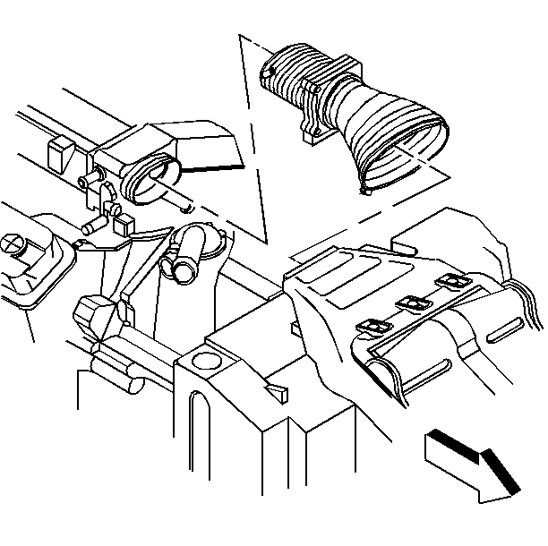
- Remove the throttle body air duct.
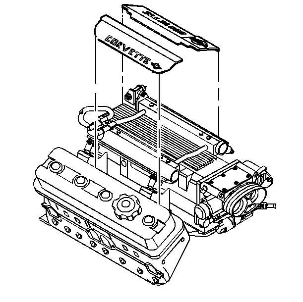
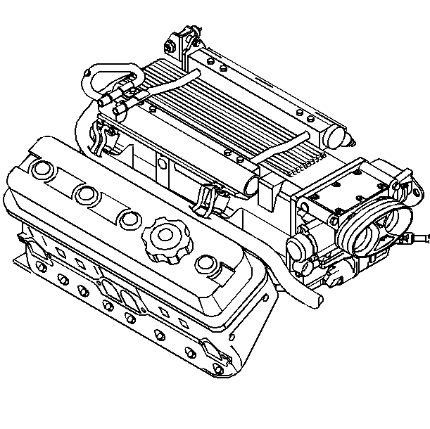
- Remove the fuel rail covers.
- Disconnect the wiring harness connectors from the fuel injectors.
- Relieve the fuel system pressure. Refer to
Caution: Remove the fuel tank cap and relieve the fuel system pressure before servicing the fuel system in order to reduce the risk of personal injury. After you relieve the fuel system pressure, a small amount of fuel may be released when servicing the fuel lines, the fuel injection pump, or the connections. In order to reduce the risk of personal injury, cover the fuel system components with a shop towel before disconnection. This will catch any fuel that may leak out. Place the towel in an approved container when the disconnection is complete.
. - Disconnect the left and right wiring harnesses and lay aside.
- Remove the accelerator cable bracket bolts, bracket and cables from the throttle body
- Remove the secondary air injection diverter valve hoses.
- Disconnect the electrical ground strap from the intake manifold.
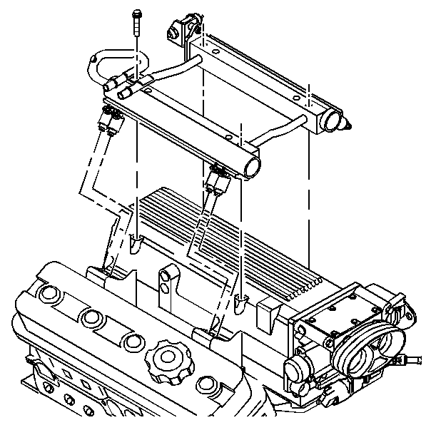
- Remove the fuel rail bolts.
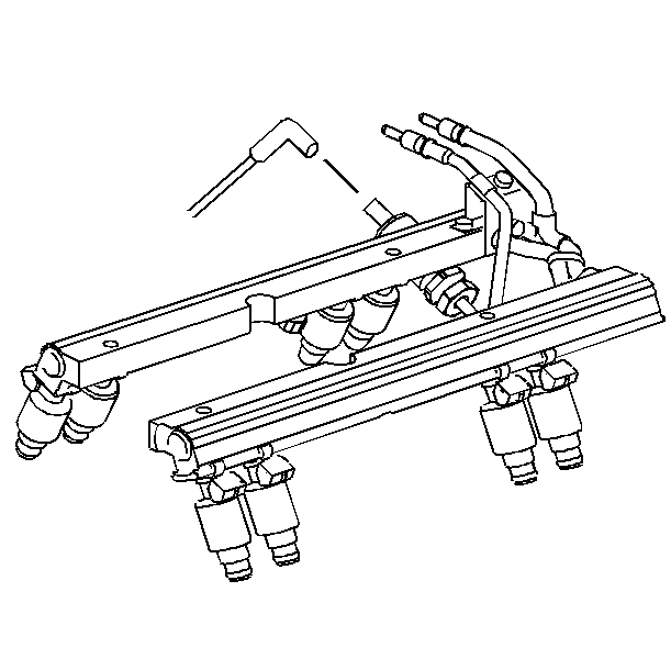
- Disconnect the fuel pressure regulator vacuum tube.
- Remove the fuel rail from the intake manifold and lay aside.
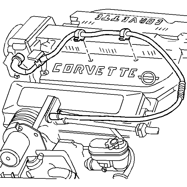
- Remove the vacuum hose.
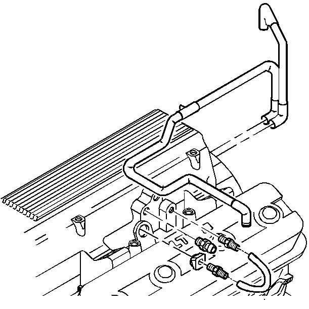
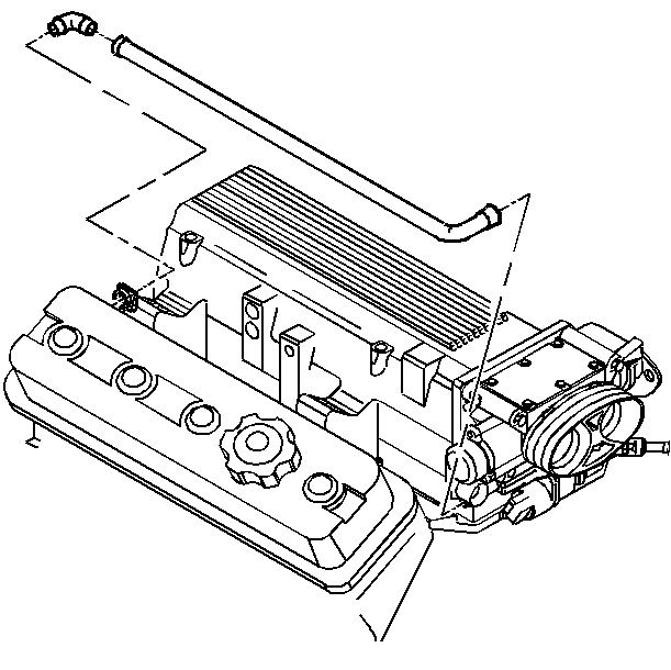
- Disconnect the crankcase vent hose.
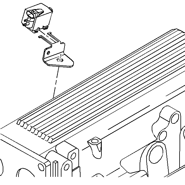
- Remove the exhaust gas recirculation (EGR) control valve nut and control valve (LT1 Engine Only).
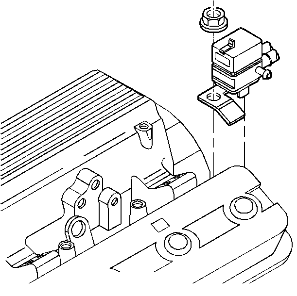
- Remove the emission canister purge control valve bracket nut and control valve.
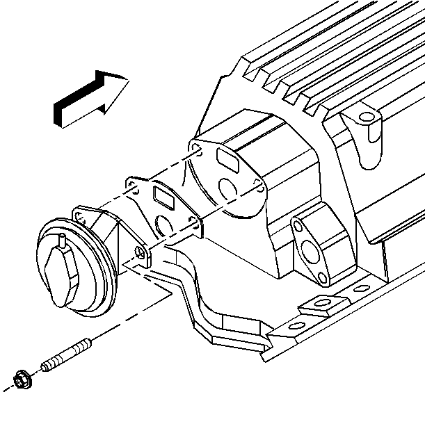
- Remove the EGR valve bolts and EGR valve (LT1 Engine Only).
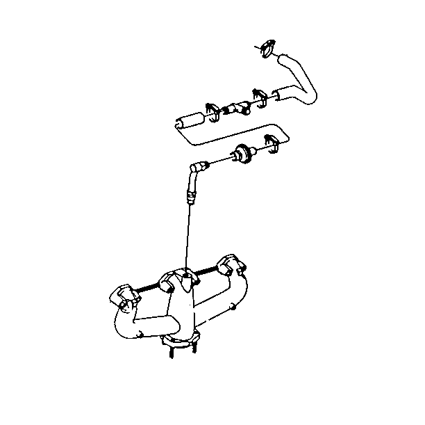
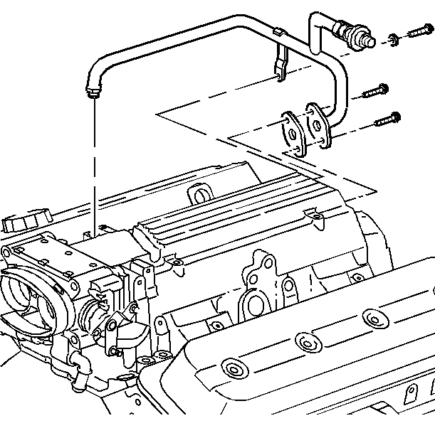
- Remove the secondary air injection pipe from the intake and the right exhaust manifold.
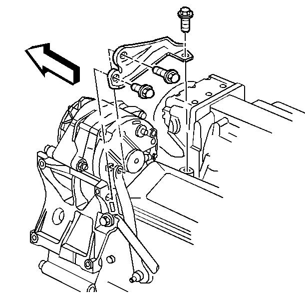
- Remove the generator brace bolts and brace.
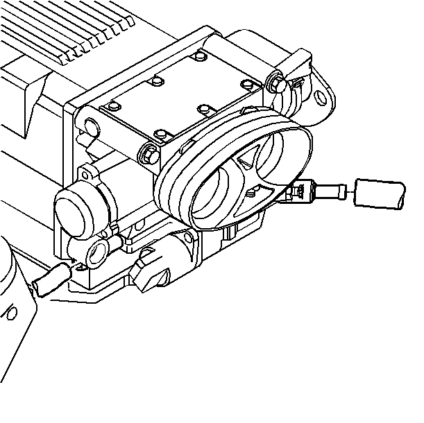
- Disconnect the coolant hose from the throttle body.
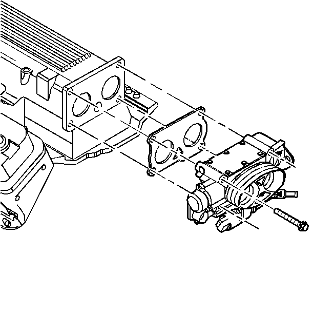
- Remove the throttle body bolts, throttle body and gasket.
- Remove the intake manifold bolts and studs.
- Remove the intake manifold assembly.
- Remove and discard the gaskets.
- Clean the following areas:

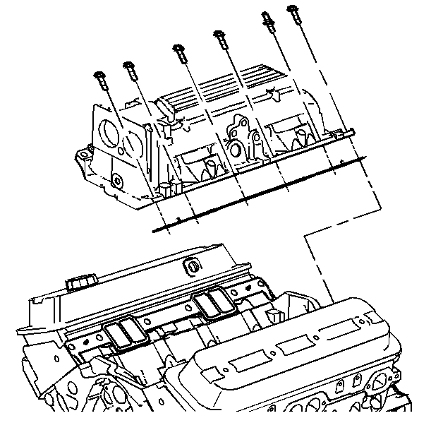
| • | The intake manifold bolts and studs |
| • | The cylinder head, engine block, and intake manifold sealing surfaces |
Installation Procedure
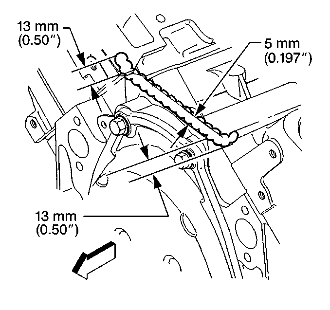
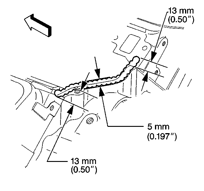
- Apply a 5 mm (0.187 in) bead of RTV sealer, GM P/N 12346141 or equivalent, to the front of the engine block. Extend the bead 13 mm (0.50 in) up each cylinder head to seal and retain the gaskets.
- Apply a 5 mm (0.187 in) bead of RTV sealer, GM P/N 12346141 or equivalent, to the rear of the engine block. Extend the bead 13 mm (0.50 in) up each cylinder head to seal and retain the gaskets.
- Install the intake manifold with new gaskets.
- Install the intake manifold bolts and studs.
- Install the throttle body, gasket and bolts.
- Connect the coolant hoses to the throttle body.
- Install the generator brace.
- Install the accelerator cable bracket and cables.
- Install the secondary air injection pipe.
- Install the EGR valve and bolts (LT1 Engine Only).
- Install the exhaust gas recirculation (EGR) control valve and nut (LT1 Engine Only).
- Install the emission canister purge control valve and bracket nut.
- Connect the crankcase vent hose.
- Connect the vacuum hose.
- Install the fuel rail to the intake manifold.
- Install the fuel rail bolts.
- Connect the fuel pressure regulator vacuum tube.
- Connect the electrical ground strap to the intake manifold.
- Install the secondary air injection diverter valve hoses.
- Connect the left and right wiring harnesses.
- Connect the wiring harness connectors to the fuel injectors.
- Install the throttle body air duct.
- Install the fuel rail covers.
- Refill with coolant. Refer to Cooling System Draining and Filling in Engine Cooling.
- Connect the negative battery cable.
- Adjust the TCS control cables. Refer to section 5E2 for information on control cable adjustments.

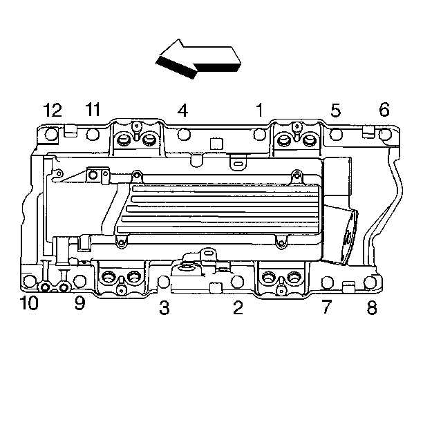
Tighten
| • | Tighten the intake manifold bolts and studs in first pass to 8 N·m (71 lb in) in sequence. |
| • | Tighten the intake manifold bolts and studs in second pass to 48 N·m (35 lb ft) in sequence. |
Notice: Use the correct fastener in the correct location. Replacement fasteners must be the correct part number for that application. Fasteners requiring replacement or fasteners requiring the use of thread locking compound or sealant are identified in the service procedure. Do not use paints, lubricants, or corrosion inhibitors on fasteners or fastener joint surfaces unless specified. These coatings affect fastener torque and joint clamping force and may damage the fastener. Use the correct tightening sequence and specifications when installing fasteners in order to avoid damage to parts and systems.

Tighten
Tighten the throttle body bolts to 25 N·m (18 lb ft).


Tighten
Tighten the accelerator cable bracket bolts to 12 N·m (106 lb in).

Tighten
| • | Tighten the secondary air injection pipe exhaust manifold fitting to 55 N·m (41 lb ft). |
| • | Tighten the secondary air injection pipe flange bolts to intake manifold to 26 N·m (19 lb ft). |
| • | Tighten the secondary air injection pipe bracket bolt to cylinder head to 40 N·m (30 lb ft). |

Tighten
Tighten the EGR valve bolts to 25 N·m (18 lb ft).

Tighten
Tighten the EGR control valve nut to 25 N·m (18 lb ft).

Tighten
Tighten the emission canister purge control valve bracket nut to 20 N·m
(15 lb ft).


Tighten
Tighten the fuel rail bolts to 10 N·m (89 lb in).


| • | Match the proper electrical connector with the fuel injector according to the cylinder number marked on the electrical connector. |
| • | If not marked, refer to SECTION 8A in order to match up wire colors and fuel injectors. |


Tighten
Tighten the negative battery cable nut to 15 N·m (11 lb ft).
