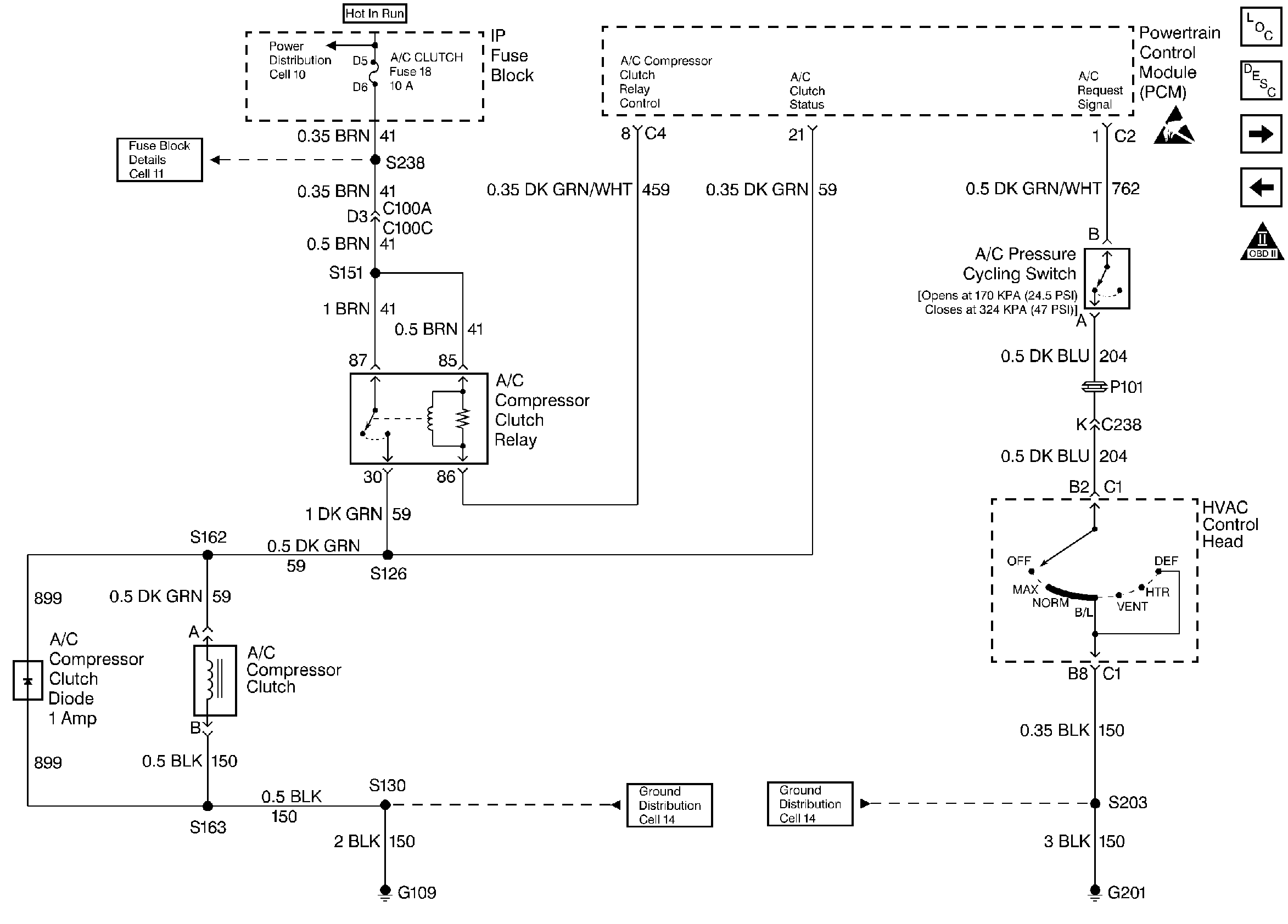
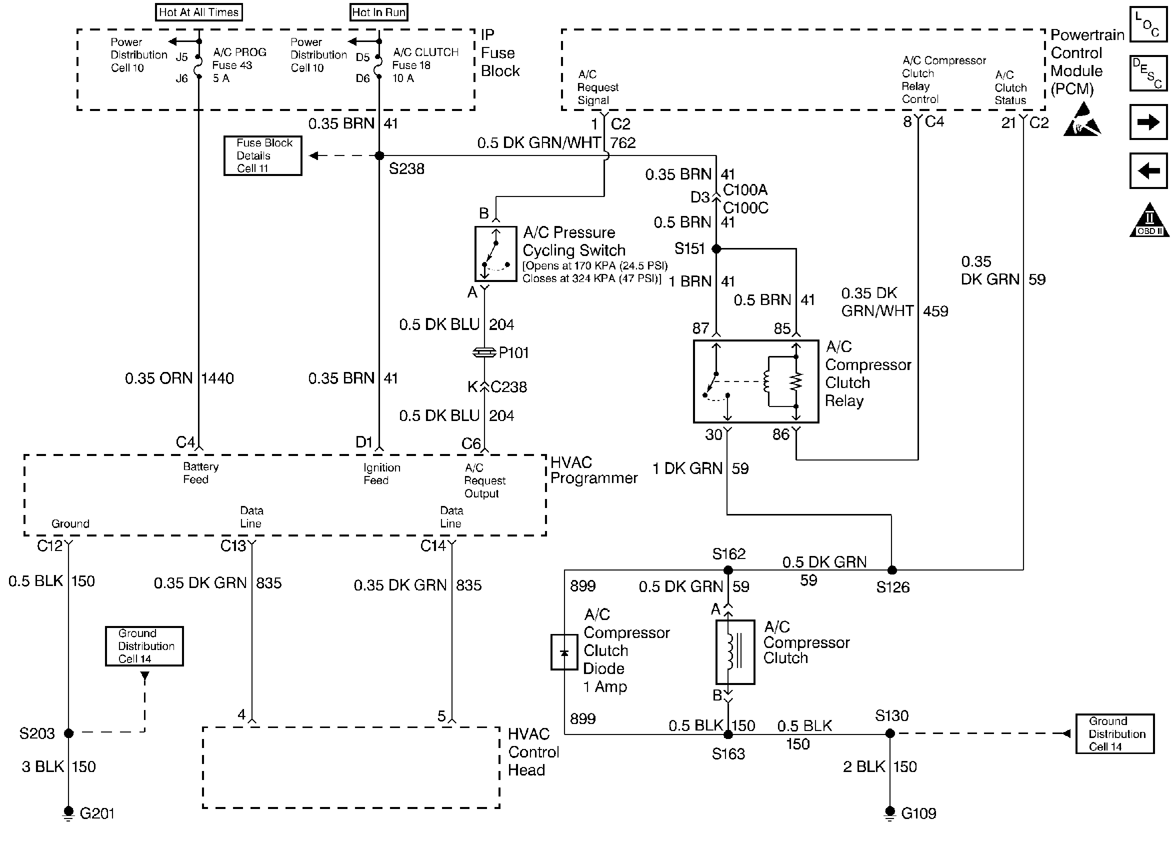
Circuit Description
When the PCM detects that A/C has been requested, the PCM will activate the A/C clutch relay. When the relay is activated, voltage should be present at both the A/C compressor clutch and the A/C clutch status terminal at the PCM.
If the PCM detects voltage on the A/C clutch status terminal when the A/C has not been requested a DTC P1539 will set.
A short to voltage at any point in the A/C status circuit, or the A/C
relay contacts are stuck, will set a DTC P1539. For the C60 system schematic
refer to
A/C Compressor Clutch Controls - C60

or for the C68 system schematic refer to
A/C Compressor Clutch Controls - C68

.
Conditions for Setting the DTC
Voltage is detected on the A/C status circuit for more than 5.0 seconds after the PCM has disengaged the A/C clutch relay.
Action Taken When the DTC Sets
| • | The DTC will be stored in the PCM memory when the diagnostic runs and fails. |
| • | The Malfunction Indicator Lamp (MIL) will not illuminate. |
| • | The PCM will record operating conditions at the time the diagnostic fails. This information will be stored in Failure Records. |
Conditions for Clearing the MIL/DTC
| • | A history DTC will clear after 40 consecutive warm-up cycles, if no failures are reported by this or any other non-emission related diagnostic. |
| • | A last test failed (Current DTC) will clear when the diagnostic runs and does not fail. |
| • | PCM battery voltage is interrupted. |
| • | Using a scan tool. |
Diagnostic Aids
| • | The A/C status circuit goes to the A/C compressor clutch and to the A/C clutch relay. Inspect all circuits going to these components. |
| • | For intermittents, refer to Symptoms . |
Test Description
Number(s) below refer to step numbers on the diagnostic table.
-
Checks if the malfunction is present. If the scan tool indicates A/C status ON, indicates the PCM has detected a voltage on the A/C status circuit with the A/C OFF.
-
If the scan tool displayed YES in the RAN column and INT in the FAIL column, indicates an intermittent condition is present. Inspect A/C status circuit for an intermittent short to B+. Refer to Symptoms . Using Freeze Frame and/or Failure Records data may aid in locating an intermittent condition. If the DTC cannot be duplicated, the information included in the Freeze Frame and/or Failure Records data can be useful in determining how many miles since the DTC set. The Fail Counter and Pass Counter can also be used to determine how many ignition cycles the diagnostic reported a pass and/or a fail. Operate vehicle within the same freeze frame conditions (RPM, load, vehicle speed, temperature etc.) that were noted. This will isolate when the DTC failed.
-
If the scan tool indicates that the test passed, indicates that the relay is shored internally.
Step | Action | Value(s) | Yes | No |
|---|---|---|---|---|
1 | Was the Powertrain On-Board Diagnostic (OBD) System Check performed? | -- | ||
Does the scan tool indicate A/C Status as ON? | -- | |||
Does the scan tool indicate that this diagnostic failed this ignition? | -- | Go to Diagnostic Aids | ||
Does the scan tool indicate DTC P1539 failed? | -- | |||
5 | Repair the A/C clutch status circuit (shorted to B+). Is the action complete? | -- | -- | |
6 | Repair the faulty A/C clutch relay. Refer to A/C Clutch Relay replacement. Is the action complete? | -- | -- | |
7 |
Does the scan tool indicate that this test ran and passed? | -- | ||
8 | Using the scan tool, select Capture Info, Review Info. Are any DTCs displayed that have not been diagnosed? | -- | Go to the applicable DTC table | System OK |
