For 1990-2009 cars only
Removal Procedure
Tools Required
J 34730-1A Fuel Pressure Gauge
- Disconnect the negative battery cable.
- Lower the vehicle.
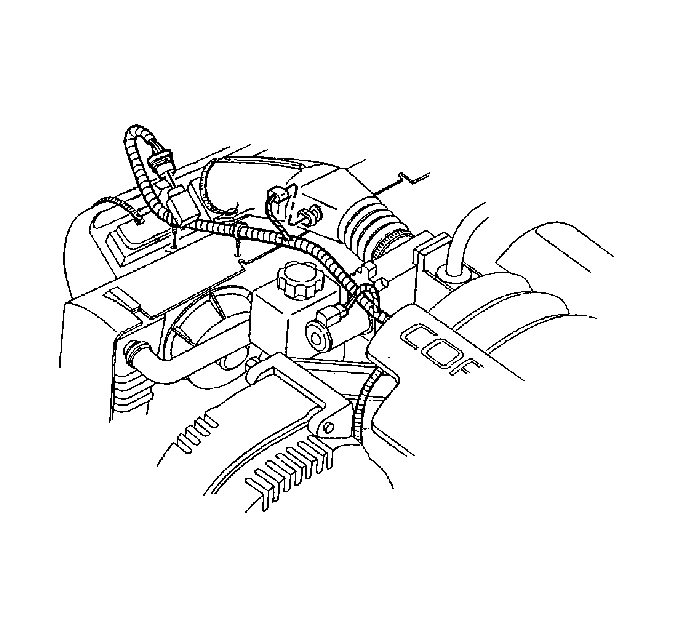
- Disconnect the intake air temperature (IAT) sensor connector.
- Disconnect the mass air flow (MAF) sensor connector.
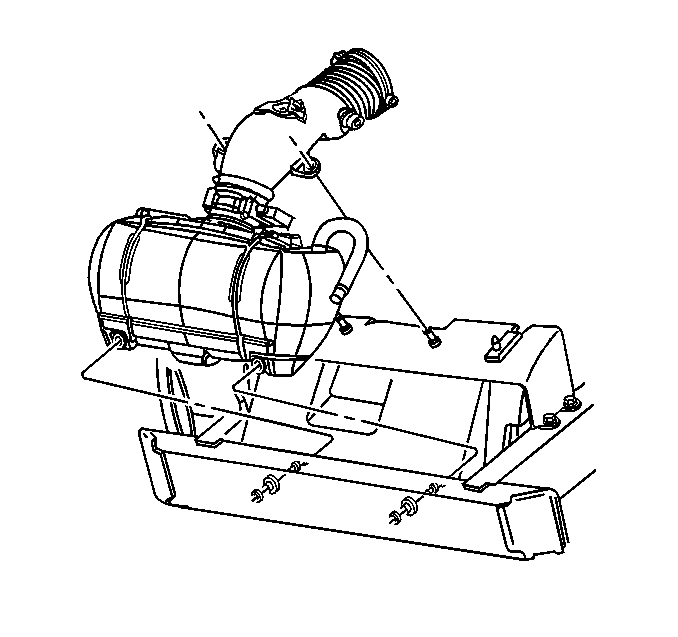
- Remove the air intake duct and air cleaner assembly.
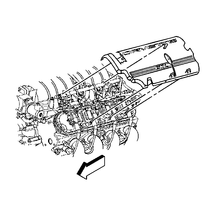
- Remove the engine beauty covers.
- Relieve the fuel system pressure using J 34730-1A .
- Disconnect the fuel line from the fuel rail.
- Remove the vacuum and crankcase vent hoses.
- Remove the throttle body coolant outlet hose from the throttle body.
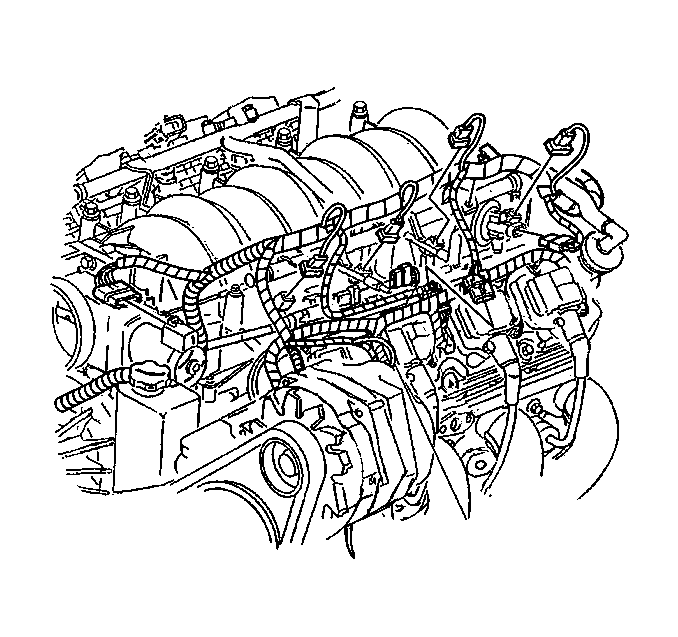
- Disconnect the fuel injector connectors.
- Disconnect all the remaining electrical connections from the intake manifold.
- Remove the intake manifold. Refer to Intake Manifold Removal .
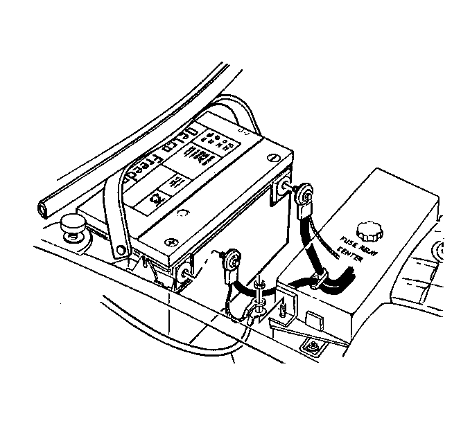
Caution: Unless directed otherwise, the ignition and start switch must be in the OFF or LOCK position, and all electrical loads must be OFF before servicing any electrical component. Disconnect the negative battery cable to prevent an electrical spark should a tool or equipment come in contact with an exposed electrical terminal. Failure to follow these precautions may result in personal injury and/or damage to the vehicle or its components.
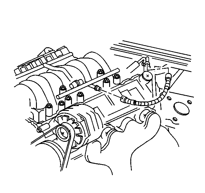
Important: Cap the fittings and plug the holes when separating the fuel system components this prevents the dripping of fuel and eliminates dirt and other contaminants from entering the fuel system.
Installation Procedure
- Install the intake manifold. Refer to Intake Manifold Installation .
- Connect the fuel injector wire harness connectors.
- Connect all remaining electrical connections to the intake manifold.
- Install the crankcase vent hoses.
- Install the vacuum hoses.
- Install the fuel line to the fuel rail.
- Install the engine beauty covers.
- Install the air intake duct and air cleaner assembly.
- Connect the MAF sensor connector.
- Connect the IAT sensor connector.
- Connect the negative battery cable.
- Program the Transmitters. Refer to Transmitter Programming/Synchronization in Keyless Entry.


Tighten
Tighten the negative battery cable bolt to 15 N·m (11 lb ft).
