Generator Circuit Diagnosis L Terminal
Circuit Description
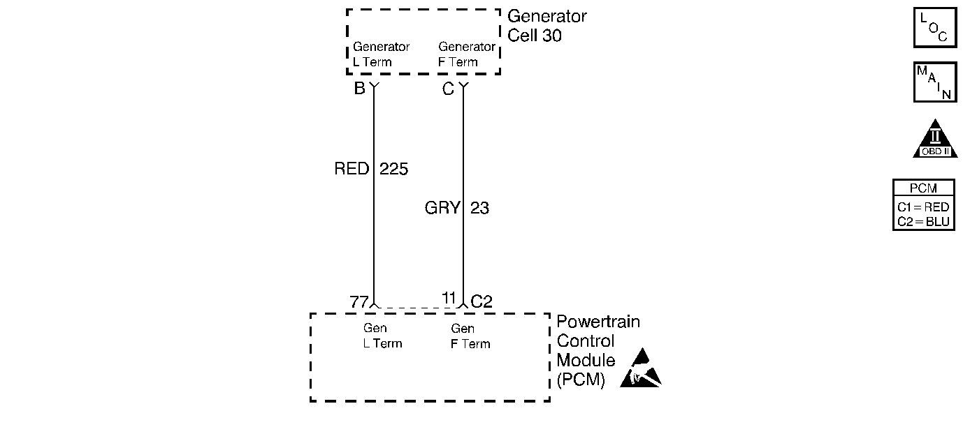
The L terminal circuit from the generator is a discrete into the PCM. The PCM supplies the ignition voltage to the generator lamp feed. This ignition voltage is pulled low by the generator once the ignition switch supplies ignition 1 voltage. The voltage stays low until the generator turns. When the generator is up and running, the PCM detects ignition voltage. Therefore, with no failures with the vehicle's charging system, the lamp terminal circuit will go low (0 volts) when the ignition switch is powered up and then goes to the ignition voltage after the engine is started.
When the charging system detects a fault (circuit shorted to ground), the Driver Information Center will display Charging System Fault.
Diagnostic Aids
A generator fault, such as a shorted output diode, malfunctioning regulator, open or shorted rotor, or open sense lead may cause a low battery charge. Refer to Engine/Engine Electrical for further information and generator diagnosis.
Use a scan tool in order to diagnosis the generator circuits. A scan tool displays Generator L Terminal Inactive when there is a problem with the L-terminal circuit.
Test Description
The numbers below refer to the step numbers on the Diagnostic Table.
-
This isolates if the generator is at fault or if the PCM and wiring are at fault.
-
A poor connection at the generator will cause a no output condition.
Step | Action | Value(s) | Yes | No |
|---|---|---|---|---|
1 | Did you perform the Powertrain On-Board Diagnostic (OBD) System Check? | -- | ||
|
Important: This table assumes there is a charging system problem. Before proceeding with this table check the generator output.
Is the voltage the same or more than the value specified? | 10V | |||
3 |
Does the circuit have continuity to ground? | -- | ||
4 | Measure the resistance between the generator harness connector terminal B and the PCM harness connector that contains the generator circuit. Is the resistance the same or less than the value specified? | 5ohms | ||
5 | Repair the short to ground in the B terminal circuit. Is the repair complete? | -- | System OK | -- |
6 | Repair the open/high resistance in the L terminal circuit. Is the repair complete? | -- | System OK | -- |
7 | Check the terminal contact at the PCM harness connector. Did you find and correct the condition? | -- | System OK | |
8 |
Important: Program the replacement PCM. Refer to Powertrain Control Module/Throttle Actuator Control Module Replacement . Replace the PCM. Is the action complete? | -- | System OK | -- |
Did you find and correct the condition? | -- | System OK | ||
10 | Repair or replace the generator. Refer to Engine/Engine Electrical. Is the action complete? | -- | System OK | -- |
Generator Circuit Diagnosis F Terminal
Circuit Description
The F terminal circuit from the generator is a pulse width modulation (PWM) signal to the PCM. The PCM detects the PWM frequency by sampling the average voltage at the F terminal of the generator. When the ignition switch supplies ignition 1 voltage, the generator goes to a predetermined duty cycle. When the generator is up and running, the generator regulator starts regulating and suppling the current. Therefore, with no failures with the vehicle's charging system, the field terminal circuit voltage will be at a low value and stay there until roughly 0.5 second after the engine idles. When the engine is idles, the voltage transitions to a higher value.
Diagnostic Aids
A generator fault, such as a shorted output diode, malfunctioning regulator, an open or shorted rotor, or an open sense lead may cause a low battery charge. Refer to Engine/Engine Electrical for further information and generator diagnosis.
Step | Action | Value(s) | Yes | No |
|---|---|---|---|---|
1 | Did you perform the Powertrain On-Board Diagnostic (OBD) System Check? | -- | ||
2 |
Does the scan tool display the specified value? | 0 Counts | ||
3 | Does the scan tool display the specified value? | 188 Counts | System OK | |
4 |
Does the parameter change from 0 to 188? | -- | ||
5 |
Does the DMM indicate continuity? | -- | ||
6 | Check continuity from the battery ground to the C terminal of the generator harness connector using the DMM J 39200 . Does the DMM indicate continuity? | -- | ||
7 | Disconnect the generator harness connector. Does the scan tool display the specified value? | 0 Counts | ||
8 | Repair the F terminal circuit for a short to voltage. Refer to Body and Accessories/Wiring Systems. Is the action complete? | -- | System OK | -- |
9 | Repair the F terminal circuit for an open. Refer to Body and Accessories/Wiring Systems. Is the action complete? | -- | System OK | -- |
10 | Repair the F terminal circuit for a grounded circuit. Refer to Body and Accessories/Wiring Systems. Is the action complete? | -- | System OK | -- |
11 |
Did you find and correct the condition? | -- | System OK | |
12 | Repair or replace the generator. Refer to Engine/Engine Electrical. Is the action complete? | -- | System OK | -- |
13 |
Is the action complete? | -- | System OK | |
14 |
Important: Program the replacement PCM. Refer to Powertrain Control Module/Throttle Actuator Control Module Replacement . Replace the PCM. Is the action complete? | -- | System OK | -- |
