Removal Procedure
Tools Required
| • | J 33432-A Transverse Leaf Spring Compressor and Adapters J 33432-97 |
| • | J 42188 Ball Joint Separator |
- Raise and support the vehicle. Refer to Lifting and Jacking the Vehicle in General Information.
- Remove the tire and wheel assembly. Refer to Wheel Removal in Tires and Wheels.
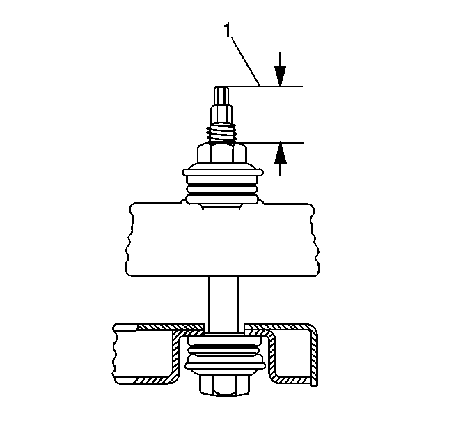
- Measure the spring stud height (1) before removing the transverse leaf spring mounting bolt.
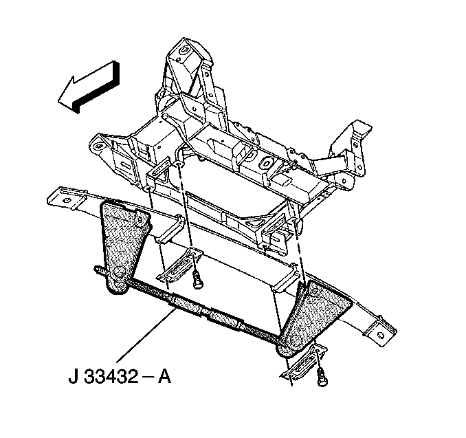
- Install J 33432-A with adapters J 33432-97 to the transverse spring, and compress the transverse spring.
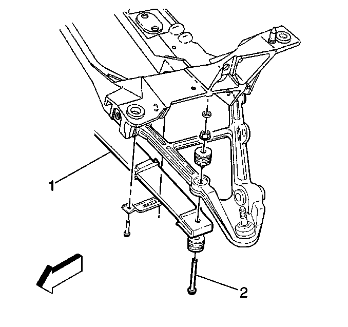
- Remove the nuts and, bolts (2), and insulators and retaining the transverse spring to the lower control arms).
- Remove the transverse spring from the control arms.
- Support the lower control arm with a jack stand.
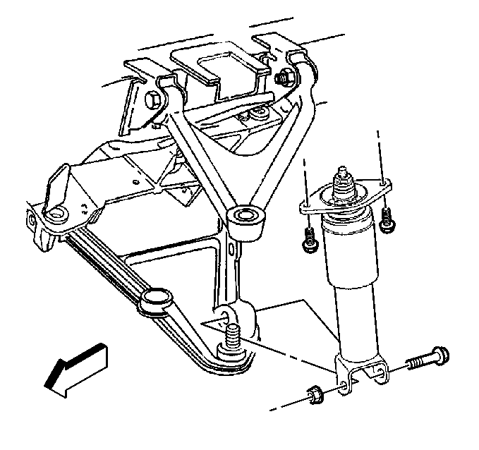
- Disconnect the shock absorber from the lower control arm.
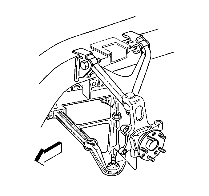
- Loosen but do not remove the lower ball joint stud nut.
- Separate the lower ball joint stud from the suspension knuckle J 42188 .
- Remove the J 42188 and the lower ball joint stud nut from the suspension knuckle.
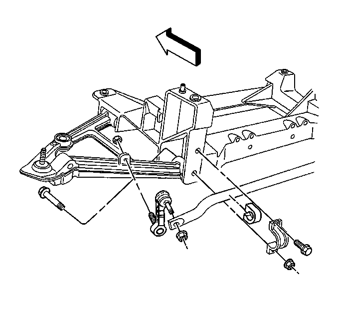
- Remove the stabilizer bar link from the lower control arm.
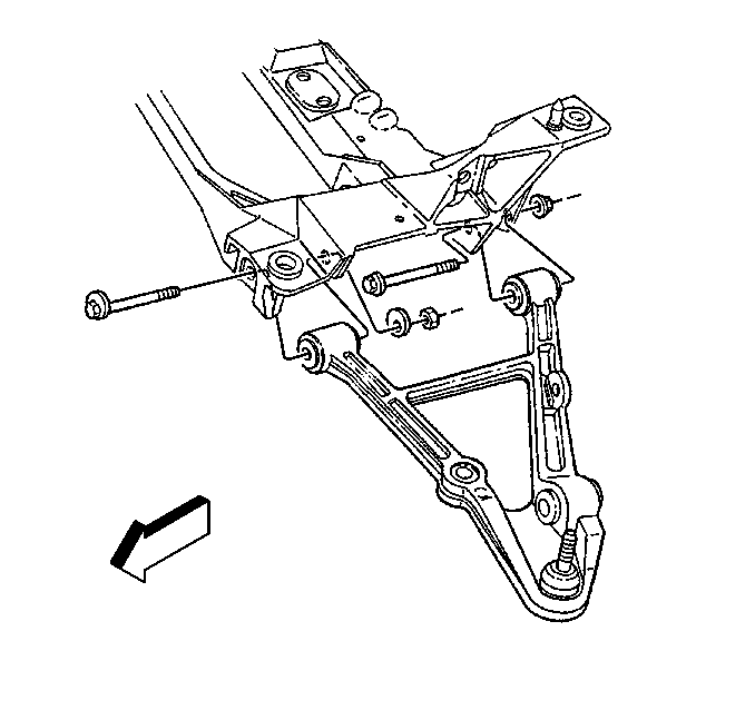
- Mark the position of and then remove the cam bolts, washers, and nuts retaining the control arm to crossmember.
- Remove the jack stand.
- Remove the control arm from the vehicle.
Installation Procedure
Tools Required
J 33432-A Transverse Leaf Spring Compressor and Adapters J 33432-97
- Install the lower control arm into the vehicle.
- Support the lower control arm a with jack stand.
- Install the cam bolts, washers, and nuts retaining control arm to crossmember.
- Install the lower control arm ball joint stud into the suspension knuckle.
- Tighten the lower control arm ball joint stud nut to 20 N·m (15 lb ft) to seat the ball joint stud.
- Turn the nut an additional 31/2 flats.
- Check the ball joint stud nut for a minimum final torque of 55 N·m (41 lb ft).
- Install the stabilizer shaft link onto control arm.
- Install the shock absorber onto the lower control arm.
- Install the transverse spring (1) onto the lower control arms.
- Install the transverse spring insulators and mounting bolts (2).
- Remove the jack stand.
- Set the transverse spring stud height (1) to the height measured during removal.
- Release and remove J 33432-A and adapters J 33432-97.
- Install the tire and wheel assembly. Refer to Wheel Removal in Tires and Wheels.
- Perform the rear wheel alignment. Refer to Wheel Alignment Measurement in Wheel Alignment.

| 3.1. | Place the cam bolts at the position marked during removal. |
| 3.2. | Due to a required wheel alignment, tighten the cam bolts but do not set them to the final torque specification at this time. |

It may be necessary to use an allen wrench to keep ball joint stud from spinning while tightening the ball joint stud nut.
Tighten
Notice: Use the correct fastener in the correct location. Replacement fasteners must be the correct part number for that application. Fasteners requiring replacement or fasteners requiring the use of thread locking compound or sealant are identified in the service procedure. Do not use paints, lubricants, or corrosion inhibitors on fasteners or fastener joint surfaces unless specified. These coatings affect fastener torque and joint clamping force and may damage the fastener. Use the correct tightening sequence and specifications when installing fasteners in order to avoid damage to parts and systems.

Tighten
Tighten the stabilizer shaft link nuts to 72 N·m (53 lb ft).

Tighten
Tighten the shock absorber lower mounting bolts to 220 N·m
(162 lb ft).


Tighten
| • | Tighten the lower control arm (front) cam bolt to 145 N·m (107 lb ft). |
| • | Tighten the lower control arm (rear) cam bolt to 95 N·m (71 lb ft). |
