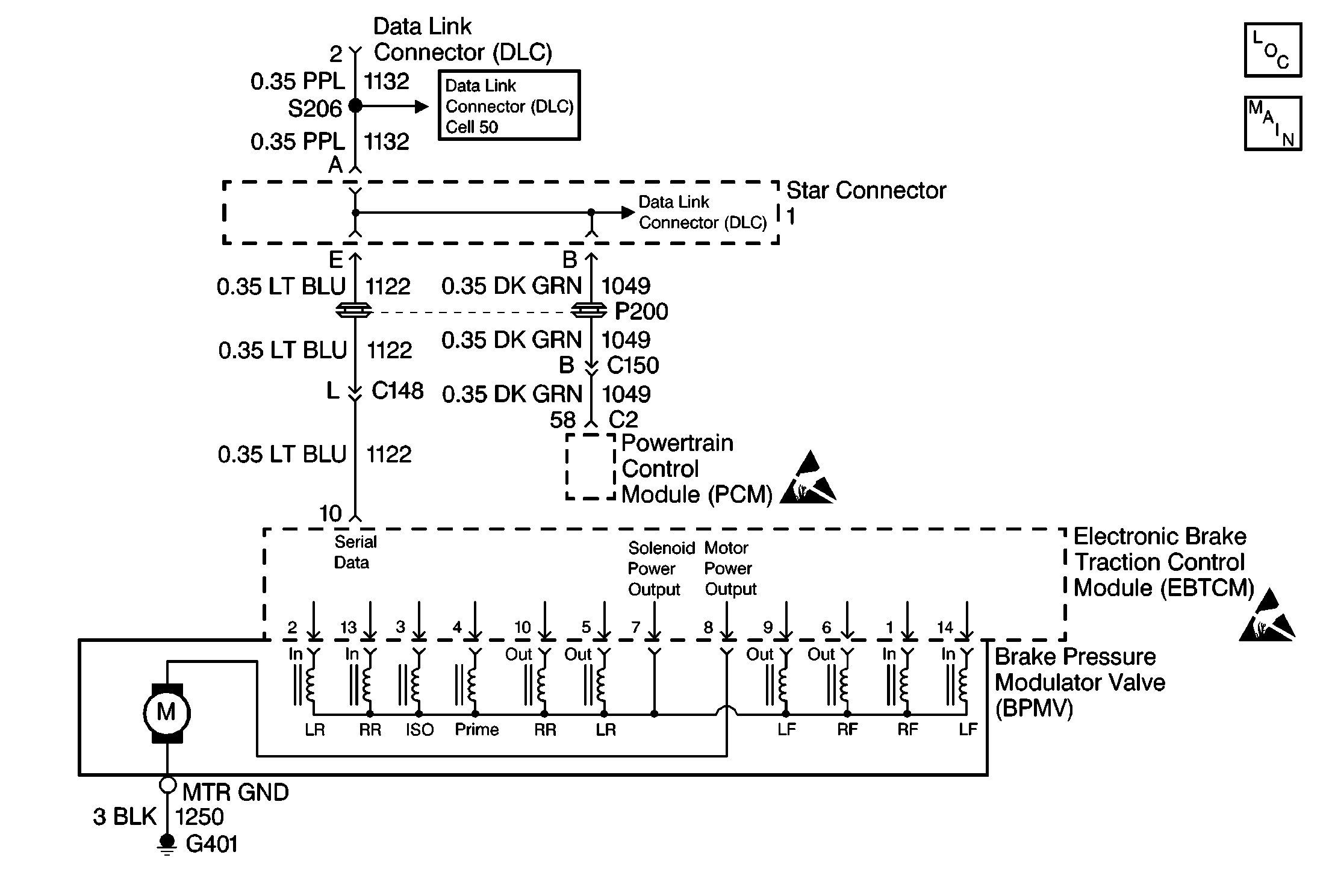
Circuit Description
The Class 2 serial data line allows all the modules on the line to transmit information to each other as needed. Each module is assigned an ID and all the information sent out on the line is assigned a priority by which it is received. When the ignition switch is turned to the ON position each module begins to send and receive information. Each module on the Class 2 serial data line knows what information it needs to send out and what information it should be receiving. What the modules do not know is which module is supposed to send them the information. This information is only learned after the module has received the information it needs along with the ID of the module that sent the information. This information is then remembered until the ignition switch is turned off. If the EBTCM never recieves the information or the ID of the module that is supposed to send the information DTC U1255 will be set..
Conditions for Setting the DTC
| • | The DTC can be set when the ignition is turned to the ON position, and the EBTCM does not recieve the PCM ID for 5 seconds. |
Action Taken When the DTC Sets
| • | A malfunction DTC is stored, TCS is disabled and the Traction Control indicator is turned On. ABS remains functional. |
Conditions for Clearing the DTC
| • | Condition for DTC is no longer present and scan tool clear DTC function is used. |
| • | Fifty ignition cycles have passed with no DTC(s) detected. |
Diagnostic Aids
| • | It is very important that a thorough inspection of the wiring and connectors be performed. Failure to carefully and fully inspect wiring and connectors may result in misdiagnosis, causing part replacement with reappearance of the malfunction. |
| • | An intermittent malfunction is most likely caused by a poor connection, rubbed through wire insulation, or a wire that is broken inside the insulation. |
| • | If an intermittent malfunction exists refer to General Electrical Diagnosis in Wiring Systems. |
| - | Class 2 transmit fault on the PCM. |
| - | Class 2 receiver fault on the EBTCM. |
| - | Open Class 2 line.. |
Step | Action | Value(s) | Yes | No |
|---|---|---|---|---|
1 | Was the Diagnostic System Check performed? | -- | Go to Diagnostic System Check | |
2 |
Does the PCM/VCM read Active? | -- | Go to Powertrain On Board Diagnostic (OBD) System Check in Engine Controls | |
3 | Does the IPC read Active? | -- | Go to IPC Diagnostic System Check in Instrument Panel, Gauges and Console | |
4 | Does the RTD read Active? | -- | Go to RTD Diagnostic System Check in Real-Time Damping (RTD) | |
5 | Does the BCM read Active? | -- | Go to Diagnostic System Check - Body Control System in Body Control System | |
6 | Replace EBTCM. Refer to Electronic Brake and Traction Control Module . Is the replacement complete? | -- | Go to Diagnostic System Check | -- |
